
Precision CNC Machined Pins Made to Your Drawings
LuckyHxs manufactures custom solid mechanical pins based on your specific 2D/3D drawings or physical samples. Whether your application requires locating, aligning, press-fitting, retaining, pivoting, guiding, or complex motion connection, we evaluate metal and engineering plastic materials to meet your exact functional needs. We support projects from initial prototypes and trial runs through to full batch production. Upload your drawing to start the engineering review.
Send your drawing, pin function, mating-hole dimensions, material, quantities, critical tolerances and inspection requirements for project review.
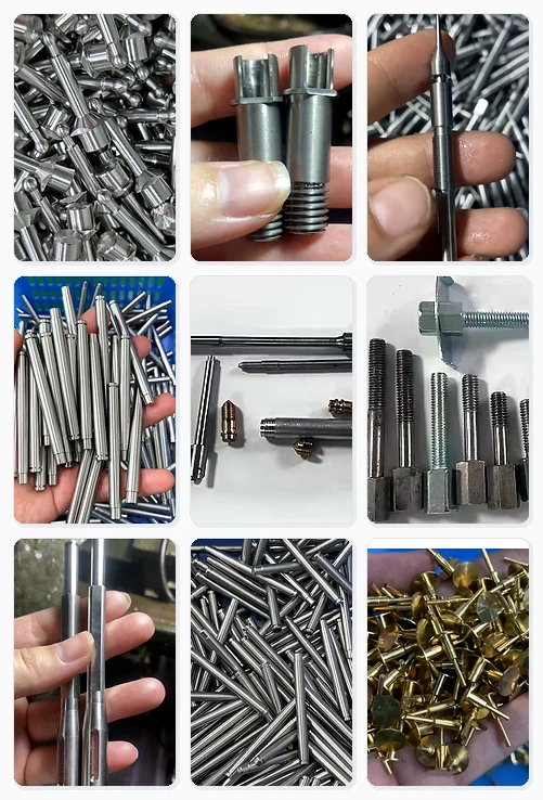
Precision CNC Machined Pins at a Glance
Manufacturing Scope
- Supply Type: Custom Made-to-Drawing
- Main Processes: CNC Turning, Swiss Machining, Turn-Mill
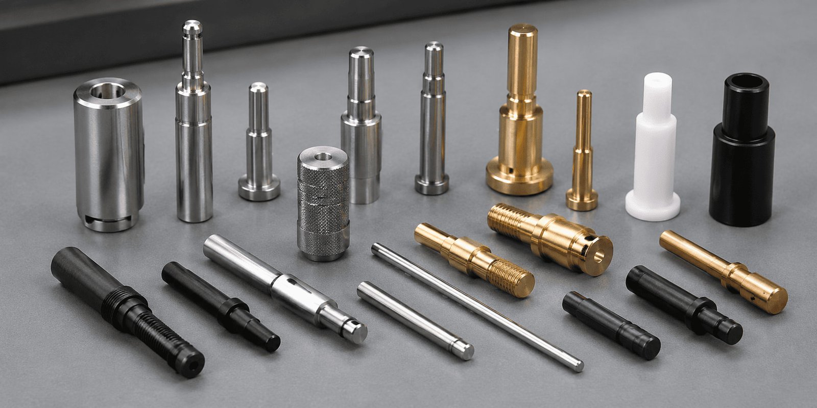
- Typical Types: Dowel, Locating, Threaded, Grooved
- Materials: Aluminum, Stainless, Steel, Brass, Plastics
- Production Support: Prototyping to Batch Production
- Required Inputs: 2D/3D CAD, Material, Qty, Tolerances
Project Parameters
- Tolerance: [CONFIRM GENERAL AND FEATURE-SPECIFIC TOLERANCE]
- Size Range: [CONFIRM PIN DIAMETER AND LENGTH RANGE]
- MOQ: [CONFIRM MOQ]
- Sample Lead Time: [CONFIRM SAMPLE LEAD TIME]
- Production Lead Time: [CONFIRM PRODUCTION LEAD TIME]
Quick Project Review
Upload initial details for a fast engineering assessment.
What Are CNC Machined Pins?
In industrial manufacturing, CNC machined pins are custom, solid mechanical components created by removing material from bar stock or other blanks using precise cutting operations. Unlike standard formed fasteners, these pins are manufactured specifically to meet the unique geometric and functional requirements detailed in a customer's engineering drawing.
Engineers design custom machined pins to perform critical functions within an assembly. These primarily include locating components with high precision, aligning mating parts during assembly, joining elements together, retaining assemblies axially, acting as pivoting axes, guiding motion, and transferring mechanical loads. Because they are machined rather than cold-headed or stamped, they offer exceptional control over dimensional accuracy and surface finish.
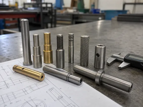
A key advantage of custom machined pins is the ability to incorporate complex, multi-functional geometry into a single solid piece. Depending on the application, a machined pin can feature multiple diameters, precision shoulders, specific head geometries, internal or external threads, straight or diamond knurls, retention grooves, tapers, flats, cross holes, chamfers, and highly application-specific end geometries. This level of customization ensures the pin performs exactly as intended in demanding mechanical, automation, or structural environments.
Clarifying Your Sourcing Intent
Machined Mechanical Pins
Examples: Dowel, locating, threaded, knurled, grooved, pivot pins.
Standard Formed Pins
Examples: Spring pins, roll pins, coiled pins, standard cotter pins.
Unrelated "Pin" Meanings
Examples: Enamel pins, lapel pins, button pins, PIN codes.
Types of Precision CNC Machined Pins We Manufacture
Explore the categories of custom solid pins we evaluate and machine based on your engineering drawings.
CNC Machined Dowel Pins
Includes precision, straight, press-fit, slip-fit, and chamfered dowel pins. Used primarily for precise alignment between mating parts. Manufactured via CNC turning or centerless grinding depending on tolerance.
RFQ Info: Pin diameter, required clearance/interference, roundness, straightness, chamfer details.
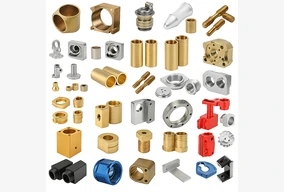
CNC Locating & Alignment Pins
Includes round locating pins, bullet-nose pins, fixture pins, and drawing-specific diamond-style pins. Essential for jigs, fixtures, and automated assembly positioning.
RFQ Info: Locating diameter, datum relationship, positioning accuracy, head geometry, mounting shank.
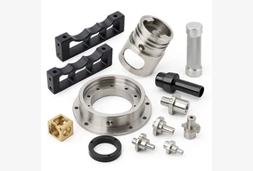
CNC Stepped & Shoulder Pins
Includes stepped, shoulder, headed, stop, multi-diameter, and flanged pins. Used to provide a positive stop or act as an axle for rotating components. CNC turning excels here.
RFQ Info: Multiple diameters, shoulder position, effective length, perpendicularity, coaxiality, fillet radius.
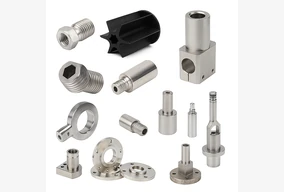
CNC Threaded Pins
Includes male, female, double-ended, partially threaded, and threaded locating pins. Combines the alignment function of a pin with the secure fastening of a screw.
RFQ Info: Thread standard, pitch, class, effective thread length, thread-to-pin concentricity, entry chamfer.
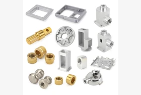
CNC Knurled Pins
Includes straight, diamond, partial, and press-fit knurled pins. Knurling displaces material to create an interference fit, ideal for permanent assembly into softer host materials like plastic or aluminum.
RFQ Info: Knurl type, knurl diameter, knurled length, mating material, installation condition.
CNC Grooved & Retaining Pins
Includes circumferential grooved pins, snap-ring groove pins, lubrication-groove pins, and multi-groove designs. Used to accept retaining rings or e-clips for axial locking.
RFQ Info: Groove position, width, depth, bottom radius, retaining-ring compatibility, burr control.
CNC Cross-Hole & Clevis Pins
Includes custom cross-drilled pins, custom clevis pins, locking pins, and linkage pins. Machined via turn-mill centers. Note: These are made-to-drawing precision pins, not standard inventory cotter pins.
RFQ Info: Cross-hole diameter, position, hole-to-axis relationship, edge distance, hole burrs.
CNC Pivot & Hinge Pins
Includes pivot pins, hinge pins, joint pins, bearing pins, and motion pins. Designed to allow rotation while supporting shear and bending loads in dynamic assemblies.
RFQ Info: Wear surface specs, straightness, surface roughness, clearance, lubrication groove, bending load.
Common Problems Buyers Face with Machined Pins
Addressing manufacturing defects before they cause assembly failures or production line interruptions.
1. Diameter & Fit Inconsistency
Assembly Impact: Loose fit causing pin walking, or excessive interference causing difficult insertion and damaged mating holes.
Specify: Exact tolerance band (e.g., +0.005/-0.000).
Review: Machine capability vs tolerance.
Evidence: Critical diameter inspection report.
2. Poor Positioning Accuracy
Assembly Impact: Misalignment of mating parts, binding during assembly, or failed retention mechanisms.
Specify: True position of critical features.
Review: Datum structure and setup method.
Evidence: CMM or optical measurement data.
3. Straightness & Runout Issues
Assembly Impact: Long pins bind during insertion; stepped pins exhibit uneven wear or eccentricity in rotation.
Specify: Straightness per unit length; Runout tolerance.
Review: Length-to-diameter ratio.
Evidence: Dial indicator runout checks.
4. Insertion/Retention Failures
Assembly Impact: Excessive assembly force damages automated equipment; low retention causes pins to vibrate loose.
Specify: Knurl specs, host material, fit type.
Review: Knurl displacement and lead chamfer.
Evidence: First-article fit test.
5. Burrs & Installation Damage
Assembly Impact: Sharp edges score mating holes, cross-hole burrs cut wires, or operators suffer injuries.
Specify: Max burr size, edge break requirements.
Review: Deburring process (manual vs automated).
Evidence: Visual or microscopic inspection.
6. Prototype-to-Production Gaps
Assembly Impact: Prototypes work perfectly, but production batches fail due to process changes or lost traceability.
Specify: Material certs, locked process routing.
Review: Scalability of the prototype method.
Evidence: Material lot records and FAI.

What Are the Different Types of Mechanical Pins?
When buyers inquire about pin types, classification is based on structure (solid or spring), sourcing model (standard or custom), manufacturing process (cold-headed or machined), or functional application, catering to design needs.
This page highlights custom machined solid pins, detailing their roles and applications in assembly.
- Locating and alignment: Ensuring two parts mate in an exact position (e.g., Dowel pins, Locating pins).
- Press-fit retention: Creating a permanent or semi-permanent joint via friction (e.g., Knurled pins, Oversized straight pins).
- Threaded fastening: Combining alignment with screw-like holding power (e.g., Threaded pins).
- Axial retention: Holding components on a shaft using external hardware (e.g., Grooved pins for snap rings).
- Pivot and hinge motion: Acting as an axle for moving parts (e.g., Pivot pins, Hinge pins).
- Cross-hole locking: Securing a joint with a secondary pin or wire (e.g., Clevis pins, Cross-drilled pins).
- Guiding: Directing the motion of a sliding component.
- Custom multi-feature pins: Combining several of the above functions into a single machined part.
Function to Pin Type Decision Guide
| Function | Recommended Starting Pin Type | Main Buyer Risk | Information Needed for RFQ |
|---|---|---|---|
| Precise Alignment | Dowel Pin / Locating Pin | Tolerance mismatch with mating hole | Diameter tolerance, required fit type |
| Permanent Joint in Plastic/Aluminum | Knurled Pin | Host material cracking or loose fit | Knurl specs, host material details |
| Axial Locking with Ring | Grooved / Retaining Pin | Burrs preventing ring installation | Groove dimensions, burr limits |
| Rotational Axis | Pivot Pin / Hinge Pin | Premature wear due to rough surface | Surface finish, straightness, load |
| Alignment + Fastening | Threaded Pin | Thread concentricity issues | Thread standard, concentricity GD&T |
CNC Machined Pins vs. Cold-Headed Pins: Which Process Fits the Project?
Choosing the right manufacturing process for custom pins heavily impacts unit cost, lead time, and design flexibility. The two primary methods for solid pins are CNC Machining (subtractive) and Cold Heading/Forming (formative).
CNC Machining rotates bar stock on a lathe, using cutting tools to shape materials with flexibility for diverse geometries like diameters, shoulders, chamfers, threads, grooves, flats, and holes. Short setup times make it ideal for prototyping, low-to-medium quantities, and designs subject to revisions. Downsides include material waste and longer cycle times per part compared to forming.
Cold Heading shapes wire or blank stock by striking it into a die, offering high speed and minimal material waste, ideal for large repeat runs. However, it demands substantial tooling investment, limits complex geometries, and makes design changes expensive.
| Requirement | Machined Pin Consideration | Cold-Headed Pin Consideration |
|---|---|---|
| Geometry Flexibility | High. Handles complex profiles, threads, and cross holes easily. | Limited. Best for simple heads and straight shanks. |
| Tooling & Setup | Low to moderate. Uses standard cutting tools and programming. | High. Requires custom dies and punches. |
| Quantity Sweet Spot | Prototypes to medium batch sizes (10s to 10,000s). | Very high volume mass production (100,000s+). |
| Material Form | Bar stock. Wide variety of alloys and plastics available. | Wire coil. Limited to highly formable metals. |
| Design Revisions | Easy. Just update the CNC program. | Difficult and costly. Requires new tooling. |
| Secondary Operations | Often completed in one setup on Turn-Mill centers. | Often required for grooves, threads, or tight tolerances. |
Question Before RFQ:
Are you looking for a few thousand highly precise, custom-featured pins (choose machining), or millions of simple standardized fasteners (choose cold-heading)? LuckyHxs focuses on the former.
What We Review Before Quoting a Machined Pin
A complete engineering drawing ensures an accurate quote and prevents downstream assembly failures.
Before Quoting, We Check More Than Price
Drawings, material, tolerances, fit, surface finish and inspection requirements are reviewed before machining.
| Review Item | What to Provide | Why It Matters |
|---|---|---|
| Design Files | 2D drawing (PDF) with revision, and 3D CAD model. | 2D defines tolerances and GD&T; 3D aids in CNC programming and quoting speed. |
| Material Specs | Specific grade, condition, and required heat treatment/hardness. | Dictates machinability, tool wear, and final part strength. |
| Quantities | Prototype quantity and expected production batch size. | Determines the optimal machining strategy and setup amortization. |
| Fit & Mating | Pin function, mating-hole dimensions, and required fit type. | Allows us to verify if the specified tolerances will actually achieve the desired assembly condition. |
| Critical Dimensions | Critical diameters, overall length, effective engagement length, shoulder/groove positions. | Identifies which features require tight process control or secondary grinding. |
| GD&T | Straightness, runout, concentricity, true position. | Crucial for long pins or multi-diameter pins to prevent binding during assembly. |
| Secondary Features | Thread specs, knurl details, cross-hole positions. | May require Turn-Mill centers or secondary setups, impacting cost. |
| Surface & Finish | Surface roughness (Ra), surface treatment (e.g., anodizing), deburring requirements. | Affects wear resistance, corrosion protection, and safe handling. |
| Quality & Logistics | Inspection documents needed, material traceability, packaging, target date. | Ensures compliance with your industry standards and safe transit. |
CNC Processes for Simple and Complex Pin Geometry
We select the optimal machining route based on your drawing's complexity, tolerance, and volume.
CNC Turning & Swiss Machining
Suitable for: Multi-diameter pins, stepped pins, and high length-to-diameter ratios (Swiss).
Value: High precision on concentric features; Swiss lathes handle long, slender pins without deflection.
Risk: Part deflection if unsupported. Drawing Info: Overall length, critical diameters, concentricity.
Turn-Mill Machining
Suitable for: Pins with flats, cross holes, off-axis features, or complex grooves.
Value: Completes complex pins in a single setup, eliminating secondary operation handling errors.
Risk: Higher hourly machine rate. Drawing Info: Cross-hole positions, flat dimensions, angular relationships.
Threading, Grooving & Knurling
Suitable for: Fastening pins, retaining pins, and press-fit assembly pins.
Value: Integrates retention mechanisms directly into the solid pin body.
Risk: Burrs left on thread or groove edges. Drawing Info: Thread class, knurl pitch, groove profile, burr limits.
Deburring and Cleaning
Suitable for: All precision pins, especially those with cross holes or grooves.
Value: Ensures smooth insertion and prevents galling or damage to mating parts.
Risk: Over-tumbling altering critical dimensions. Drawing Info: Edge break specs, cleanliness requirements.
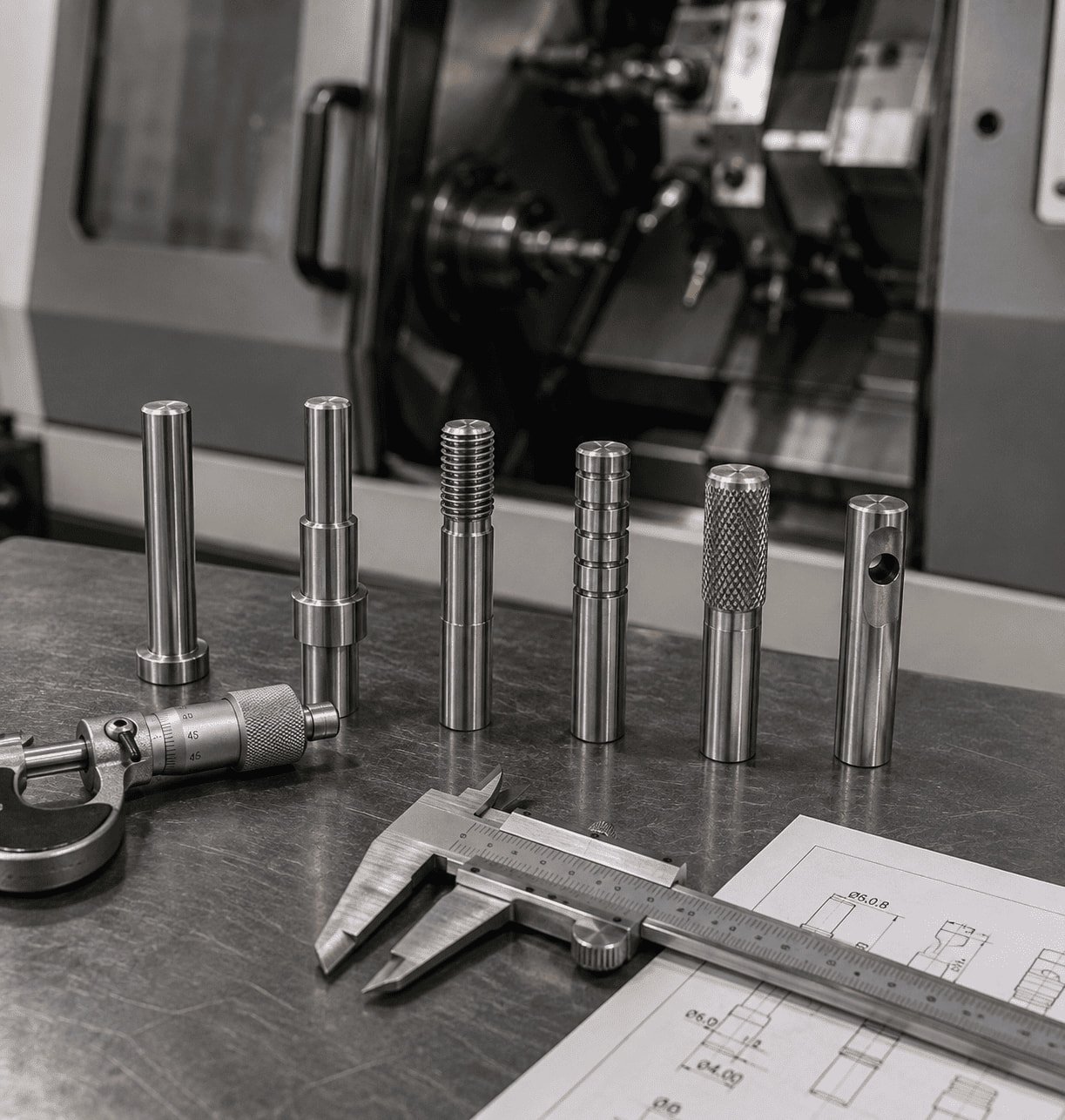
Design Tip: Pins with flats, cross holes, off-axis features, or complex grooves may require turn-mill machining or secondary operations. Minimizing these features where not functionally necessary can reduce costs.
Materials and Finishes for Custom Machined Pins
| Material Category | Recorded Grades | Functional Reason | Buyer Watch Point |
|---|---|---|---|
| Aluminum | 6061, 6063, 7075, 2024, 5052 | Lightweight, corrosion resistant, easy to machine. | Lower shear strength; anodizing alters final diameter. |
| Stainless Steel | 303, 304, 316, 316L | High strength, excellent corrosion resistance, sanitary. | 304/316 are tougher to machine; watch for galling in tight fits. |
| Free-Machining Steel | 1214, 1215 | Excellent machinability for high-volume, low-cost pins. | Requires plating or oiling to prevent rapid rusting. |
| Brass & Copper | H57/C3602, H59/C3604, H62 | Low friction, non-sparking, electrical conductivity. | Soft material; susceptible to wear under heavy shear loads. |
| Engineering Plastics | POM (Delrin), PTFE (Teflon) | Self-lubricating, non-marring, electrical insulation. | High thermal expansion; difficult to hold extremely tight tolerances. |
Surface Finishes
Available depending on material and project requirements. Examples include Anodizing, Plating, Black oxide, Sandblasting, and Polishing.
How Pin Fit, Alignment and Feature Location Affect Assembly
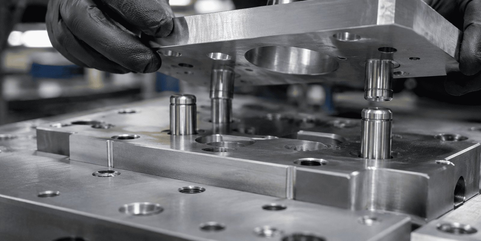
The primary function of most machined pins is to interact with a mating hole. The success of this interaction depends entirely on the specified fit and the control of geometric features. If tolerances are mismatched, the assembly will either be too loose to function or impossible to put together.
Types of Fit:
• Clearance Fit: The pin is always smaller than the hole. Used for pivot pins, hinge pins, or slip-fit dowels where free movement or easy manual assembly is required.
• Transition Fit: The tolerances overlap, meaning the pin could be slightly smaller or slightly larger than the hole. Used for precise locating where a light tap might be needed for assembly.
• Interference (Press) Fit: The pin is always larger than the hole. Used for permanent or semi-permanent retention, requiring mechanical force to assemble.
Beyond simple diameter, Geometric Dimensioning and Tolerancing (GD&T) is critical. When multiple pins are used to align two plates, the true position of the holes and pins dictates whether they will mate. A pin that is perfectly sized but mislocated will cause binding.
Furthermore, straightness is vital for long, slender pins; a bowed pin will act larger than its measured diameter during insertion. For stepped or shoulder pins, runout or coaxiality ensures that different diameters share the same centerline, preventing eccentric rotation or uneven seating against the shoulder. Clear datum selection on your drawing tells the machinist which feature is the most critical reference point.
| Functional Requirement | Drawing Callout to Discuss | Failure if Unclear |
|---|---|---|
| Easy manual assembly | Clearance fit tolerances | Pin jams during insertion |
| Permanent retention | Interference fit tolerances | Pin walks out under vibration |
| Multi-pin alignment | True position & Hole spacing | Plates bind, assembly impossible |
| Deep hole insertion | Straightness per unit length | Pin binds halfway down the hole |
| Rotating stepped axle | Runout / Coaxiality | Eccentric wobble, uneven wear |
RFQ Checklist for Fit Issues
- Host material: What is the pin going into?
- Hole-making process: Drilled, reamed, or molded?
- Fit type: Expected clearance or interference.
- Installation method: Manual press, automated, or heat shrink?
- Engagement length: How deep does it seat?
- Removal requirement: Permanent or serviceable?
- Required retention evidence: Push-out force testing needed?
Why Is Pin Insertion Force Too High or Retention Too Low?
Two of the most common complaints in pin assembly are: "We can't press it in without bending it," and "The pins are falling out during operation." Both issues stem from a mismatch between the pin's geometry and the host environment.
When Insertion Force is Too High: This occurs when the combined tolerance of the pin diameter and hole diameter creates too much interference. However, it's not just about diameter. A lack of a proper lead-in chamfer on the pin forces the sharp edge to shave material off the hole wall. High surface roughness on the pin increases friction. If the pin is plated or anodized, the coating thickness (often ignored in the raw machining drawing) might push the final dimension out of spec. Finally, if the hole is deep and misaligned, the pin will bind. Overly high assembly force can damage the pin, score the hole walls, crack brittle host materials (like certain plastics or cast aluminum), or stall automated assembly equipment.
When Retention is Too Low: This happens when the interference is insufficient, or the engagement length is too short to provide enough frictional holding area. In knurled pins, if the knurl geometry (pitch and depth) isn't aggressive enough for the specific host material, it won't displace enough material to lock in place. Poor retention leads to pins walking out under vibration, components loosening, loss of alignment, or catastrophic joint failure.
Solving these issues requires reviewing the host material, the hole-making process (drilled holes act differently than reamed holes), the installation method, and the specific retention features designed into the pin.
How Much Does It Cost to Have Precision Pins Made?
Buyers frequently ask, "How much does it cost to have pins made?" or "Why are custom pins expensive compared to catalog parts?" The cost of custom CNC machined pins is driven by a combination of material, machining time, complexity, and volume.
Material and Volume: The raw material grade and bar size set the baseline cost. More importantly, setup and programming time must be allocated across the order quantity. A prototype run of 50 pins bears a high setup cost per unit. As batch sizes increase to thousands, the setup cost is amortized, dropping the unit price. However, unlike cold-heading, the unit price will not drop indefinitely; it eventually bottoms out at the base cycle time required to machine the part.
Complexity and Features: A simple straight dowel pin is fast to turn. Adding tight fit requirements (GD&T) slows down the process and increases inspection time. Adding threads, knurls, grooves, or cross holes increases cycle time. If a cross hole is off-axis, it might require a more expensive Turn-Mill center or a secondary setup, adding handling costs.
Secondary Requirements: Heat treatment, surface treatments (plating, anodizing), extensive deburring, specialized packaging, and comprehensive material documentation all add to the final delivered cost.
Custom Pin Cost Structure
Where Can You Get Custom Mechanical Pins Manufactured?
Depending on your project's maturity, volume, and customization level, you have several options for sourcing mechanical pins.
1. Standard Pin Catalogs/Distributors: Best for off-the-shelf spring pins, standard dowels, or cotter pins. Ideal when your design can accommodate standard sizes and you need parts immediately. They do not support custom drawings or modified features.
2. Cold-Heading/Forming Suppliers: Best for massive volumes (hundreds of thousands) of relatively simple pins. They offer the lowest piece price at scale but require high tooling investments and long lead times for first articles. Not suitable for complex features or iterative designs.
3. Connector-Pin Specialists: Focused exclusively on micro-pins for electrical connectors (stamped or screw-machined). Not typically suited for larger structural, locating, or heavy-duty mechanical pins.
4. Direct CNC Machining Factories (Like LuckyHxs): Best when you have a specific CAD drawing, require special fits, multiple diameters, threads, knurls, grooves, or cross holes. We provide direct engineering communication, handle design revisions easily, offer wide material options, and manage inspection documents for prototypes through repeat production batches.
What Makes a Pin Strong Enough for Its Application?
Engineers often ask, "What are the strongest pins?" or "What are the best pins to use?" The reality is that there is no universal "best" pin. The optimal strength and material depend entirely on the specific service conditions of your assembly.
Pin selection depends on evaluating multiple forces:
• Shear Load: Forces acting perpendicular to the pin axis, trying to slice it.
• Bending Load: Forces acting on an unsupported gap along the pin.
• Fatigue & Shock: Repeated dynamic loading or sudden impacts.
A common misconception is that harder or stiffer pins are always better. A harder, more rigid pin might survive a high load, but it could transfer that stress directly to a softer host material, causing the mating hole to elongate or the housing to crack. Conversely, a pin that is too soft might bend or suffer fatigue failure under dynamic loads.
Other critical factors include engagement length, repeated insertion requirements, exposure to corrosion or extreme temperatures, and the acceptable consequences of failure (e.g., does the pin need to shear cleanly to protect a more expensive component?). Final material, hardness, heat treatment, and dimension specifications must be confirmed based on your engineering requirements.
DFM Guidelines for More Manufacturable Custom Pins
Design for Manufacturability (DFM) reduces machining time, lowers costs, and improves part consistency.
1. Apply tight tolerances only to functional diameters.
Impact: Reduces grinding/inspection time. Decision: Loosen tolerances on non-mating sections.
2. Define the mating hole and required fit.
Impact: Clarifies the actual functional goal. Decision: Provide mating part details in RFQ.
3. Use clear datums and GD&T.
Impact: Guides machining setup and inspection. Decision: Apply runout/position to critical features only.
4. Avoid unnecessary slenderness.
Impact: Long, thin pins deflect during turning. Decision: Increase diameter or accept Swiss machining costs.
5. Use practical shoulder radii.
Impact: Perfectly sharp inside corners cause stress and tool wear. Decision: Allow a small fillet radius or an undercut.
6. Define the lead-in chamfer.
Impact: Prevents assembly damage. Decision: Specify chamfer angle and length.
7. Use standard thread forms where practical.
Impact: Custom threads require special tooling. Decision: Stick to standard UN/Metric profiles.
8. Use manufacturable groove profiles.
Impact: Deep, narrow grooves are hard to cut cleanly. Decision: Match groove to standard retaining rings.
9. Review cross-hole edge distance.
Impact: Holes too close to the end cause breakout. Decision: Ensure sufficient material around the hole.
10. Separate cosmetic and functional surfaces.
Impact: High finishes everywhere increase cost. Decision: Specify Ra only where it matters for wear/fit.
11. Define dimensions after finishing.
Impact: Plating adds thickness. Decision: Clearly state if tolerances apply before or after plating.
12. Clarify burr and cleanliness requirements.
Impact: Dictates the deburring method. Decision: Specify max burr size and edge break.
13. Review whether secondary setups can be reduced.
Impact: Multiple setups increase handling cost and error risk. Decision: Align features to be machined from one direction if possible.
From Pin Drawing Review to Repeat Production
RFQ & Drawing Review
Input: CAD, Qty, Material.
Review: Completeness.
Fit & DFM Confirmation
Review: Tolerances vs Capability.
Risk Reduced: Assembly failure.
Quote & Sample Plan
Review: Cost & Lead time.
Decision: PO approval.
First-Article Production
Review: Initial setup & FAI.
Risk Reduced: Process errors.
Assembly Approval
Input: Client fit test.
Decision: Batch release.
Production & Packing
Review: Batch inspection.
Risk Reduced: Transit damage.
Inspection Evidence for Repeatable Machined Pins
Addressing the core pain points through documented quality control and dimension verification.
- Drawing revision control: Ensuring the correct version is machined.
- Material and lot records: Traceability back to the raw bar stock.
- First-article inspection: Verifying setup before batch runs.
- Critical diameter checks: Using micrometers or optical comparators.
- Length and shoulder checks: Ensuring proper seating depth.
- Straightness & Runout: Critical for long pins and stepped axles.
- Coaxial features: Verifying alignment of multiple diameters.
- Thread & Knurl inspection: Go/No-Go gauges and visual checks.
- Groove profile & Cross-hole position: Preventing retention failures.
- Burr and cleanliness: Microscopic or visual verification.
- Surface-finish review: Profilometer checks for wear surfaces.
- Batch identification: Labeling for inventory control.
- Packaging: Methods to protect critical dimensions in transit.
- Nonconformance communication: Transparent handling of deviations.
Note on Documentation: Inspection reports and material documents are not automatically included with every order. Please specify your requirements during the RFQ stage so they can be accurately quoted.
Inspection equipment is selected according to the feature, tolerance and reporting requirement. [CONFIRM INSPECTION EQUIPMENT]
Applications for Made-to-Drawing Machined Pins
1. Jigs & Fixtures
Types: Locating, Dowel, Bullet-nose.
Function: Precise positioning of workpieces.
Risk: Rapid wear degrading datum accuracy.
RFQ Info: Hardness, locating diameter tolerance.
2. Industrial Automation
Types: Stepped, Cross-hole, Grooved.
Function: Actuator linkages and robotic joints.
Risk: Binding due to poor straightness.
RFQ Info: Clearance fit specs, surface finish.
3. Machinery & Equipment
Types: Threaded, Knurled, Heavy Dowel.
Function: Structural alignment and shear load transfer.
Risk: Pin shearing under heavy load.
RFQ Info: High-strength alloy selection.
4. Motors & Motion Systems
Types: Precision Stepped, Coaxial pins.
Function: Rotor alignment, gear positioning.
Risk: Eccentricity causing vibration.
RFQ Info: Runout and concentricity GD&T.
5. Linkages & Hinges
Types: Pivot, Clevis, Grooved.
Function: Rotational axis for moving arms.
Risk: Galling or premature wear of mating hole.
RFQ Info: Lubrication grooves, wear surface Ra.
6. Electronics & Connectors
Types: Small Brass/Copper pins, Knurled.
Function: High-current contacts, housing alignment.
Risk: Poor conductivity or plastic housing cracking.
RFQ Info: Plating specs, knurl displacement.
7. Molding & Tooling Support
Types: Ejector pins (custom), Core pins.
Function: Mold alignment, part ejection.
Risk: Flash due to loose fit, or seizing due to heat.
RFQ Info: Thermal expansion consideration, exact fit.
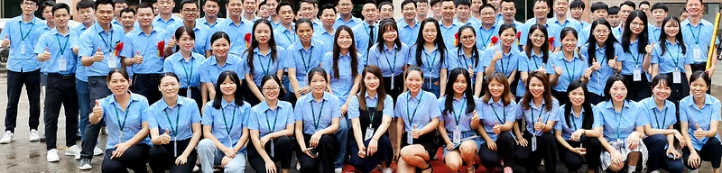
See the Factory Behind Your Machined Pins
Take a look at our production environment, machining capabilities, and quality certifications.
Certificates and Test Documents Available for Review
Certificate holder, scope, number and validity must be checked against the original documents before publication. [CONFIRM CERTIFICATE DETAILS]
Precision CNC Machined Pins FAQ
What are CNC machined pins?
What types of mechanical pins can be CNC machined?
Do you sell standard spring pins or roll pins?
What information is needed to quote a custom pin?
How do you determine the correct pin and mating-hole fit?
Can you machine dowel, locating, threaded, knurled and cross-hole pins?
What materials are available for custom pins?
What tolerances can you hold?
Can you control straightness, runout and concentricity?
How do you control burrs around grooves and cross holes?
Can you support prototypes and repeat production?
How much do custom machined pins cost?
When should a pin be machined instead of cold headed?
Can inspection and material documents be provided?
How should precision pins be packed?
Request a Precision CNC Machined Pins Quote
To ensure an accurate manufacturing review and quotation, please provide as much detail as possible about your custom pin project. Your drawings and project information will be used only for quotation and engineering review.
Information to Include:
- 2D/3D drawing and revision
- Pin type and function
- Material and material condition
- Prototype quantity & Production quantity
- Critical diameters & Overall/effective length
- Mating-hole dimensions & Required fit
- GD&T (Straightness or runout)
- Threads, Knurling, Grooves, Cross holes
- Surface roughness & Surface treatment
- Deburring and cleanliness requirements
- Inspection documents & Material traceability
- Packaging & Target delivery date
Drawing & Project Confidentiality
Your drawings, CAD files, and project information will be used only for quotation, manufacturability review, and project communication. If your project requires an NDA or a specific document-handling procedure, tell us before submitting sensitive files.
- Project files used for quotation and engineering review
- NDA requirements can be discussed before submission
- Drawing revision and document scope confirmed per project
Direct Contact
admin1@lucky-hxs.com
+86 13342931453
Shenzhen Bao'an Songgang