
Custom CNC Machining Parts Factory for Made-to-Drawing Components

LuckyHxs manufactures precision metal and engineering plastic components directly from your 2D drawings and 3D CAD files. We provide comprehensive engineering review to optimize manufacturability, supporting your project requirements from initial prototyping through to stable, repeat volume production.

Made to Your Drawing CNC Turning & Milling Prototype to Production Metal & Engineering Plastics
Discuss Your Machining Project

Send your CAD files, material, quantities, critical tolerances, surface finish and inspection requirements for project review.

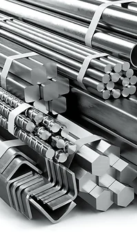
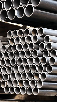
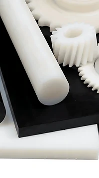
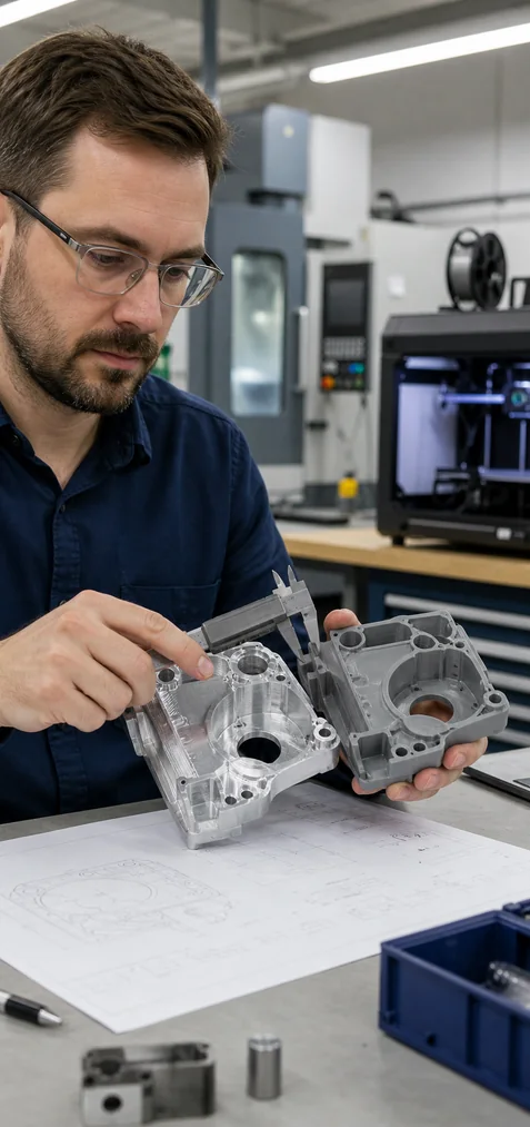
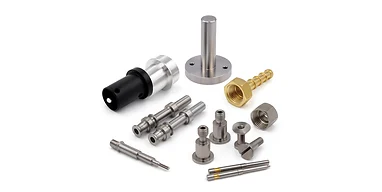
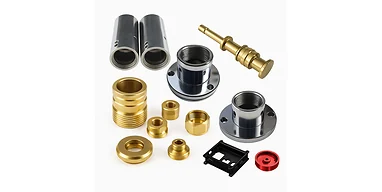
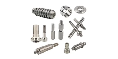
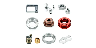
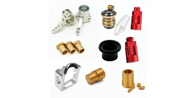
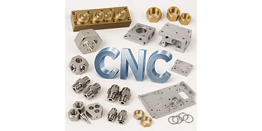
Various custom CNC machined metal and plastic components manufactured by LuckyHxs factory

Custom CNC Machining Parts at a Glance

Capabilities

  • Supply Type: Made-to-Drawing Manufacturer
  • Main Processes: CNC Turning, Milling, Turn-Mill, Swiss
  • Typical Parts: Shafts, Bushings, Housings, Fasteners
  • Materials: Aluminum, Stainless, Steel, Brass, Plastics

Project Parameters

  • Drawing Inputs: 2D PDF (Required) + 3D CAD (STEP/IGES)
  • Tolerance: [CONFIRM GENERAL AND FEATURE-SPECIFIC TOLERANCE]
  • Size Range: [CONFIRM MACHINING SIZE RANGE]
  • Production Support: Prototype & Repeat Volume

Logistics & MOQ

  • MOQ: [CONFIRM MOQ] (Subject to project review)
  • Sample Lead Time: [CONFIRM SAMPLE LEAD TIME]
  • Production Lead Time: [CONFIRM PRODUCTION LEAD TIME]
CUSTOM CNC MACHINING EXPLAINED

What Are Custom CNC Machining Parts?

Custom CNC machining parts are made-to-drawing components produced from metal or engineering-plastic stock using computer-controlled cutting tools. Unlike standard catalog parts, their geometry, material, tolerances, finish, and inspection requirements are defined by the buyer’s 2D drawings and 3D CAD files.

CNC Turning

Best suited to round and rotational features such as shafts, sleeves, pins, bushings, external diameters, bores, grooves, tapers, and threads. The workpiece rotates while a cutting tool removes material.

CNC Milling

Used for flat surfaces, pockets, slots, hole patterns, mounting features, and more complex multi-directional geometry. The cutting tool rotates while moving across a stationary or indexed workpiece.

Parts that combine rotational and prismatic features may require turn-mill machining or multiple setups. The appropriate process route should be determined by part geometry, datums, GD&T requirements, material machinability, quantity, surface finish, and inspection needs.

What Buyers Should Provide

For an accurate engineering review, provide the latest drawing revision, 3D CAD file where available, material, quantity, critical tolerances, surface-finish requirements, and expected inspection documentation.

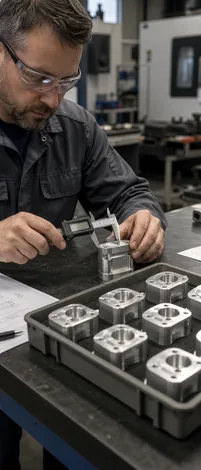
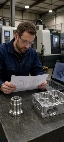
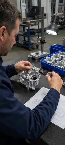
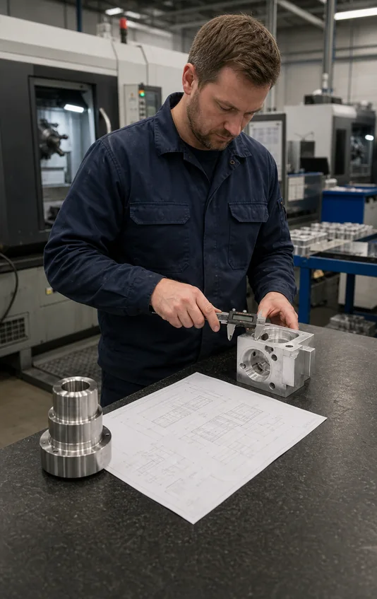
Machinist reviewing drawing and inspecting custom CNC turned and milled parts

Made-to-drawing components reviewed against project requirements.

Custom CNC Machining Parts We Manufacture

We review your drawings to determine the optimal machining strategy for these typical component categories.

Custom CNC machined precision stepped shafts and motor spindles

Custom CNC Machined Shafts

Typical parts include stepped shafts, motor shafts, transmission shafts, and precision spindles. These rotational geometries are primarily processed via CNC turning. Critical quality risks involve diameter fit, runout, concentricity across multiple steps, straightness over long lengths, and surface finish on bearing or sealing surfaces. Buyers must clearly specify keyway dimensions and cross-hole positions.

CNC machined plain and flanged bushings and bearing sleeves

CNC Machined Bushings & Sleeves

Encompassing plain bushings, flanged bushings, bearing sleeves, and wear sleeves. These hollow cylindrical parts require precise CNC turning and boring. Critical manufacturing points include maintaining ID/OD fit tolerances, ensuring concentricity between inner and outer diameters, controlling thin-wall deformation during clamping, and rigorous burr control on internal edges.

Precision CNC machined dowel pins, locating pins and spacers

CNC Machined Pins & Spacers

Including dowel pins, locating pins, threaded pins, grooved pins, and precision spacers. Often processed on Swiss-type CNC lathes for high efficiency and accuracy. Quality focus is on dimensional repeatability across large batches, end-face perpendicularity, precise groove positioning for retaining rings, and specific knurling or thread conditions required for assembly.

Custom CNC machined internally and externally threaded inserts and fasteners

CNC Threaded Inserts & Fasteners

Custom internally or externally threaded inserts, drawing-specific nuts, studs, and specialized fasteners. Manufactured via turning and milling. Buyers must specify the exact thread standard (Metric, UNC, UNF), thread class, engagement length, and entry chamfer requirements. Manufacturing review ensures thread gauge compliance and proper installation features.

CNC milled instrument housings, electronic enclosures and valve bodies

CNC Machined Housings & Enclosures

Instrument housings, electronic enclosures, valve bodies, and pump housings. These prismatic components require multi-axis CNC milling. Critical reviews focus on the datum structure, hole position accuracy, flatness of sealing surfaces, machining access for internal cavities, thin-wall vibration risks, internal cleanliness, and the protection of external cosmetic surfaces.

CNC machined equipment brackets, sensor mounts and fixture components

CNC Machined Brackets & Mounts

Equipment brackets, sensor mounts, motor mounts, and structural fixture components. Typically CNC milled from block material. Quality depends on maintaining flatness, precise hole positioning, perpendicularity between mounting faces, and managing assembly stack-up tolerances. Buyers should note how post-machining surface treatments might affect critical mounting dimensions.

Common Problems Buyers Face with Custom CNC Parts

Understand the manufacturing risks that can cause assembly delays, rework, and inconsistent production—and what should be confirmed before machining begins.

Dimensional and GD&T inspection of a custom CNC machined component
01

Dimensional and GD&T Inconsistency

Business Impact

Parts that pass basic caliper checks but fail GD&T (like runout or true position) lead to immediate assembly failure, interference, or premature wear in dynamic systems.

What to Specify

Clearly mark critical datums and feature-specific tolerances on the 2D PDF drawing, distinct from general block tolerances.

Manufacturing Review

We review datum structures to design machining fixtures that minimize setup changes, reducing tolerance stack-up during cutting.

Inspection Evidence

CMM (Coordinate Measuring Machine) reports verifying specific GD&T callouts against datums.
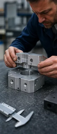
Test fitting mating CNC machined parts to verify assembly tolerances
02

Poor Assembly Fit and Tolerance Stack-Up

Business Impact

Individual parts may be in tolerance, but when assembled, excessive clearance or tight binding occurs, damaging mating components or causing sealing problems.

What to Specify

Indicate mating parts, required fits (e.g., H7/g6), and assembly direction if critical.

Manufacturing Review

We evaluate how multiple tolerances interact and may suggest adjusting nominal dimensions to ensure the statistical center of the tolerance band favors assembly.

Inspection Evidence

Go/No-Go gauge checks or functional assembly testing with provided mating components.

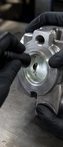
Inspection of burrs and internal contamination in a CNC machined part
03

Burrs, Sharp Edges and Internal Contamination

Business Impact

Undetected internal chips or burrs in fluid control parts (valves, pumps) can break loose during operation, causing catastrophic system contamination or seal failure.

What to Specify

Define edge break requirements (e.g., "Break all sharp edges 0.2mm max") and specify if internal cross-holes require special deburring.

Manufacturing Review

We plan specific in-machine chamfering tools and post-machining ultrasonic cleaning steps for intersecting fluid paths.

Inspection Evidence

Visual inspection under magnification and documented cleaning protocols.

Surface-finish inspection of custom CNC machined parts
04

Surface Finish and Finishing Variation

Business Impact

Excessive tool marks can cause O-ring leaks. Inconsistent anodizing or plating results in cosmetic inconsistency and rejected consumer-facing products.

What to Specify

Call out specific Ra/Rz values for sealing faces. Separate functional surfaces from cosmetic surfaces, noting masked areas.

Manufacturing Review

We select appropriate feed rates and tool nose radii to achieve as-machined finish requirements before any chemical treatments alter dimensions.

Inspection Evidence

Profilometer readings for roughness and visual limit samples for color/texture.

Comparison of an approved prototype with a CNC production batch
05

Prototype-to-Production Inconsistency

Business Impact

Prototypes pass testing, but the production batch exhibits batch instability, forcing difficult quality investigations and production line halts.

What to Specify

Inform the supplier if a prototype is intended for future volume production so scalable processes are used from day one.

Manufacturing Review

We avoid using unscalable manual setups for prototypes if volume is expected, designing hard fixtures and standardized CNC programs early.

Inspection Evidence

First-Article Inspection (FAI) reports for the production run compared against approved prototype data.

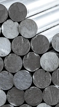
Material batch identification and inspection traceability for CNC parts
06

Material and Inspection Traceability

Business Impact

Without proof of material grade, parts may fail under load. Lack of traceability makes root-cause analysis impossible during field failures.

What to Specify

Request material certificates and specific dimensional reports at the RFQ stage, not after production begins.

Manufacturing Review

We ensure material stock is segregated and linked to specific job travelers throughout the factory floor.

Inspection Evidence

Mill test certificates, heat numbers, and lot-controlled inspection records.

Which CNC Process Fits Your Part Geometry?

The final machining route is never random. It is determined by a combination of geometry, material, tolerance, quantity, feature access, and inspection requirements.

Part Geometry Recommended Starting Process Typical Parts Key Review Point
Primarily cylindrical, rotational symmetry CNC Turning Shafts, plain bushings, round flanges Length-to-diameter ratio (rigidity)
Prismatic, flat faces, pockets, complex 3D profiles CNC Milling (3, 5-axis) Housings, brackets, base plates Internal corner radii and tool access
Small diameter (<32mm), long, high volume Swiss CNC Machining Medical pins, slender shafts, micro-fasteners Bar stock straightness requirements
Cylindrical base with off-axis holes/flats Turn-Mill Machining Complex spindles, hydraulic spools Minimizing setups to hold tight true position
Simple rotational, massive volume, loose tolerance Automatic Lathe Machining Basic spacers, simple standoffs Economic viability vs precision needs

What We Review Before Quoting Your CNC Parts

Missing information leads to inaccurate pricing. Here is how specific drawing inputs directly affect process planning and cost.

Review Item How Missing Information Affects Quote, Process, or Risk
2D and 3D drawing revision Without a marked revision level, older CAD files may be machined, resulting in scrap. 2D PDFs are required to confirm tolerances not present in 3D models.
Material and grade "Aluminum" is insufficient. 6061 machines differently than 7075. Ambiguity leads to overpricing to cover material risk or tool wear.
Prototype vs. Production quantity Quoting 10 pieces requires manual fixture assumptions; quoting 1,000 pieces allows amortization of custom hard tooling for faster cycle times.
Datums and GD&T Lack of datums means the machinist guesses how the part mounts, potentially causing tolerance stack-up and assembly failure.
Threads and fits Without thread classes (e.g., 6H vs 4H), we cannot select the correct thread gauge or tap, risking loose connections.
Burr and cleanliness requirements Default deburring may not suffice for fluid/medical parts. Unspecified cleanliness risks internal system contamination.
Surface treatment Anodizing adds thickness. If not specified, pre-machining dimensions won't account for plating buildup, causing tight fits later.
Inspection reports & Packaging Full CMM reports and custom blister packaging add labor cost. Assuming they are free defaults leads to commercial disputes.

Materials for Custom CNC Machined Components

Custom CNC machined aluminum components

Aluminum

Grades: 6061, 6063, 7075, 2024, 5052

Advantages: Excellent machinability, high strength-to-weight ratio, good thermal conductivity.

Suitable For: Enclosures, brackets, aerospace prototypes.

Risks: Thin-wall deformation due to internal stress; anodizing color variation across different batches.

Custom CNC machined stainless steel parts

Stainless Steel

Grades: 303, 304, 316, 316L

Advantages: High corrosion resistance, excellent strength, medical/food grade options.

Suitable For: Valve bodies, medical instruments, marine hardware.

Risks: Work hardening during machining (especially 304/316); slower cycle times increasing cost.

Free-machining steel CNC turned components

Free-Machining Steel

Grades: 1214, 1215

Advantages: Extremely fast machining speeds, excellent chip formation, cost-effective for volume.

Suitable For: High-volume pins, standard fasteners, non-corrosive environment shafts.

Risks: Poor corrosion resistance requiring immediate plating; lower tensile strength than alloy steels.

Custom CNC machined brass and copper parts

Brass & Copper

Grades: H57/C3602, H59/C3604, H62

Advantages: Low friction, electrical conductivity, spark resistance, aesthetic appeal.

Suitable For: Electrical contacts, plumbing fittings, decorative hardware.

Risks: Material cost volatility; softness can lead to handling damage before assembly.

Custom machined engineering plastic components

Engineering Plastics

Grades: POM (Delrin), PTFE (Teflon), Selected plastics subject to confirmation

Advantages: Insulating properties, chemical resistance, low friction, lightweight.

Suitable For: Wear pads, insulators, fluid manifolds, medical trial devices.

Risks: High thermal expansion causing dimensional drift during measurement; difficulty holding extremely tight tolerances compared to metals.

Final grade availability and specifications are confirmed during quotation.

Surface Finishing Options and Drawing Considerations

Finish Common Objective Buyer Must Specify Dimensional or Appearance Watch Point
As-Machined Cost-efficiency, tightest tolerance retention Required Ra/Rz roughness value Visible tool marks remain; zero added thickness.
Anodizing (Type II / III) Corrosion resistance, wear resistance, color Color, Type, and masking areas Adds dimensional thickness; threaded holes may require masking or oversized tapping.
Plating (Zinc, Nickel) Corrosion protection, conductivity, aesthetics Plating thickness and standard Uneven buildup on sharp corners; critical fits must account for plating thickness.
Black Oxide Mild corrosion resistance, reduced light reflection Acceptable visual variation Negligible dimensional change; offers minimal wear protection compared to plating.
Sandblasting Uniform matte appearance, removing light tool marks Grit size and masking Can alter tight dimensional tolerances or damage sealing surfaces if not masked.
Polishing High cosmetic gloss, reduced friction Target Ra value Manual polishing can cause inconsistent geometry on sharp edges.

Available depending on material and project requirements.

How Much Does It Cost to Get a Part CNC Machined?

Calculating the cost of custom CNC machining parts is not based on a flat hourly rate or a simple weight-based formula. Because every component is made-to-drawing, the price is a direct reflection of the manufacturing effort required to meet your specific tolerances, geometry, and volume.

A general relative formula for understanding your quote is:

Estimated Cost = Material + Setup Allocation + Machining Time + Tooling + Secondary Operations + Inspection + Finishing + Packaging

Setup and Programming: This is a fixed cost per batch. For a prototype quantity of 5 pieces, the hours spent programming the CAM software and physically setting up the machine fixtures are divided among those 5 parts, resulting in a high unit price. For a production quantity of 5,000 pieces, that same setup cost is heavily amortized, significantly reducing the per-unit price. However, unit prices do not decrease at a fixed, infinite ratio; eventually, the cycle time and material become the dominant cost floor.

Machining Time and Complexity: The cycle time is dictated by material machinability and part complexity. Aluminum machines much faster than 316 Stainless Steel, reducing machine-hour costs. Parts requiring 5-axis machining to reach complex undercuts will cost more per hour than simple 3-axis milled plates, though 5-axis can sometimes save money by reducing the number of manual setup changes.

Tolerances and GD&T: Tight tolerances directly inflate costs. Demanding ±0.005mm where ±0.05mm would suffice forces the factory to use fresh tooling, run slower feed rates, and perform frequent CMM inspections. Similarly, complex GD&T requirements may necessitate specialized workholding to prevent part distortion during cutting.

Cost Driver Why It Changes Price What the Buyer Can Provide
Raw Material & Stock Size Exotic grades or oversized stock requiring heavy material removal increases cost. Allow standard material grades if functional requirements permit.
Tight Tolerances Requires slower cutting, specialized tools, and higher scrap risk. Apply tight tolerances only to critical mating surfaces.
Order Quantity Amortizes setup, programming, and documentation costs. Provide both prototype and expected annual volume for accurate scaling.
Documentation Full FAI reports and material certs require administrative and engineering labor. Specify exactly which reports are mandatory for compliance.

What Makes a Rapid CNC Machining Project Move Faster?

In custom manufacturing, "rapid" does not mean a guaranteed fixed number of days regardless of geometry. True speed is achieved by eliminating friction during the engineering review and requirement confirmation phases.

Machining speed depends heavily on material availability, realistic tolerances, and surface treatment requirements (which often require external vendors). To expedite your project, ensure your initial RFQ package is comprehensive. Unclear drawing revisions or missing thread callouts lead to Requests for Information (RFIs), halting the timeline before cutting even begins.

Fast-Track Input Checklist

  • Complete 3D CAD files (STEP/IGES) and 2D PDF drawings.
  • Clear drawing revision marked.
  • Confirmed material grade (e.g., Al 6061, not just "Al").
  • Realistic tolerances applied only where functional.
  • Explicit surface treatment and inspection requirements.

Rapid Workflow

1 RFQ Submission
2 Engineering Review
3 Requirement Confirmation
4 CNC Machining
5 Quality Inspection
6 Packing and Shipment

Current estimated sample cycle: [CONFIRM SAMPLE LEAD TIME]

Where Can You Get Custom CNC Machined Aluminum Parts?

Aluminum is the most frequently requested material for custom CNC machining due to its excellent machinability, strength-to-weight ratio, and responsiveness to surface treatments. However, no single aluminum alloy is the "best" material for all projects.

Aluminum 6061 is the industry standard, offering a balanced mix of strength, weldability, and corrosion resistance, ideal for general brackets and housings. Aluminum 7075 provides significantly higher strength—comparable to many steels—making it suitable for highly stressed aerospace or automotive prototypes, though it is harder to anodize consistently. Aluminum 6063 is often preferred for intricate custom extrusions requiring excellent surface finish, while 2024 offers high fatigue resistance but poor corrosion resistance, and 5052 is renowned for its formability in sheet metal but can be gummy during CNC cutting.

When sourcing aluminum parts, critical discussions with your factory should include thin-wall deformation risks, as internal material stresses can cause aluminum to warp after heavy material removal. Additionally, if the parts require cosmetic anodizing, buyers must specify acceptable color variations, clearly define masked areas (especially for conductive contact areas), and note how post-finishing dimensions will affect tight assembly tolerances.

Alloy or Requirement Typical Consideration What to Confirm
Al 6061 vs 7075 7075 is stronger but more expensive and harder to anodize cleanly. Confirm if maximum strength is truly required over cost.
Thin-Wall Sections Vibration during milling causes chatter marks and dimensional drift. Confirm allowable wall thickness or accept modified cutting paths.
Cosmetic Anodizing Tool marks will show through clear anodizing. Confirm pre-anodize surface roughness (Ra) requirements.

CNC Machining vs. 3D Printing: Which Fits Your Prototype?

The right prototype process depends on what you need to validate. 3D printing is often useful for early form and geometry checks, while CNC machining is better suited to prototypes that require production-intent materials, functional testing, or machined surface characteristics.

01

Choose 3D Printing When

  • You need to review external form, ergonomics, or assembly space.
  • The design contains internal cavities that are difficult to machine.
  • Fast design iteration is more important than production-material behavior.
  • The prototype is primarily for visual or early-stage geometry validation.
Best for: Early form and design validation
02

Choose CNC Machining When

  • The prototype must be tested under functional load.
  • Production-intent metal or engineering-plastic material is required.
  • Dimensional relationships, mating features, or surface finish must be evaluated.
  • The project is moving toward pilot or repeat production.
Best for: Functional and production-intent validation

Many projects use both processes: 3D printing for early design review, followed by CNC machining for functional testing and pilot production.

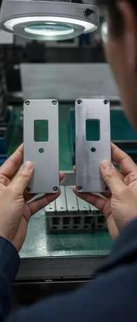
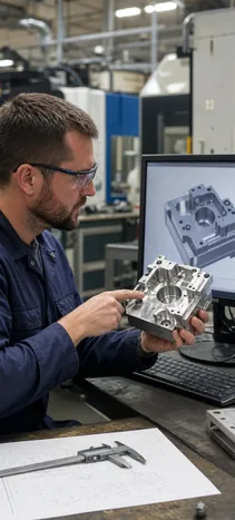
Engineer comparing a CNC machined prototype with a 3D printed prototype

Select the prototype process based on what the part must prove.

DFM Choices That Improve Manufacturability and Quoting Accuracy

1. Apply tight tolerances only to functional features.

Impact: Blanket tight tolerances force slow machining everywhere. Decision: Loosen non-mating dimensions.

2. Define clear datums and GD&T.

Impact: Ambiguity leads to setup errors and stack-up. Decision: Mark primary mounting faces as datums.

3. Use practical internal corner radii.

Impact: Sharp internal corners require slow EDM or tiny tools. Decision: Add radii >1/3 of cavity depth.

4. Avoid unnecessarily deep and narrow cavities.

Impact: Tool deflection causes chatter and poor finish. Decision: Limit depth-to-width ratio to 4:1.

5. Use standard holes and threads where practical.

Impact: Custom threads require custom taps or slow thread milling. Decision: Stick to standard metric/UNC sizes.

6. Separate cosmetic and functional surfaces.

Impact: Over-polishing functional faces alters dimensions. Decision: Clearly denote cosmetic-only zones.

7. Consider tool access.

Impact: Undercuts require 5-axis machines or special tools. Decision: Design features accessible from standard axes.

8. Review thin-wall geometry.

Impact: Walls < 1mm warp during machining. Decision: Thicken walls or accept higher scrap rates.

9. Reduce unnecessary setups.

Impact: Features on 6 sides require 6 manual flips, increasing cost. Decision: Consolidate features to fewer faces.

10. Define post-finishing dimensional requirements.

Impact: Anodizing adds thickness, seizing tight fits. Decision: State "Dimensions apply AFTER coating".

From CAD Review to Repeat Production

A structured review process helps align drawings, functional requirements, inspection expectations, and repeat-production needs before manufacturing begins.

Engineer reviewing a customer drawing for a custom CNC machining RFQ
1

Drawing & RFQ Review

Buyer Provides: 2D/3D files, material requirements, expected quantities, and target application.
Review Focus: Drawing completeness, part geometry, critical features, and missing RFQ information.
Why It Matters: Helps identify unclear or potentially difficult-to-manufacture requirements before quotation.
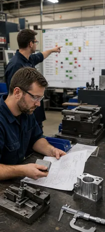
Engineers reviewing the manufacturability of a custom CNC machined part
2

DFM Review & Requirement Confirmation

Buyer Provides: Functional requirements, mating relationships, and critical quality expectations.
Review Focus: Tool access, datum strategy, tolerance relationships, machining route, and inspection needs.
Why It Matters: Helps identify potential manufacturing and cost risks before production planning.
CNC machining project quotation and sample planning review
3

Quotation & Sample Plan

Buyer Provides: Expected quantities, project stage, and requested delivery schedule.
Review Focus: Material availability, process route, sample requirements, and commercial details.
Why It Matters: Aligns technical scope, sample expectations, and quotation assumptions.
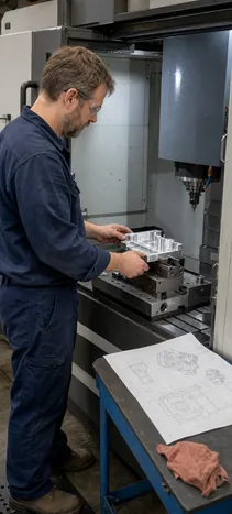
First-article production of a custom CNC machined component
4

First-Article Production

Buyer Provides: Confirmation of the approved drawing revision and any sample-specific requirements.
Review Focus: Machining setup, tooling approach, fixture stability, and critical features.
Why It Matters: Provides a controlled opportunity to evaluate the proposed manufacturing route.
Inspector checking a first-article CNC machined part against the drawing
5

Inspection & Approval

Buyer Provides: Sample feedback and confirmation of any required inspection documentation.
Review Focus: Specified dimensions, mating features, surface requirements, and agreed inspection records.
Why It Matters: Helps confirm that the sample aligns with the approved drawing and project requirements.
Repeat-production CNC parts organized for inspection and packaging
6

Repeat Production & Delivery

Buyer Provides: Approved sample status, order quantity, packaging needs, and delivery information.
Review Focus: Process consistency, drawing revision control, lot identification, and packaging requirements.
Why It Matters: Supports clearer repeat-order communication and production traceability.

Ready to Review Your CNC Project?

Send your drawing, material, quantity, critical requirements, and project stage for an engineering review.

Chat on WhatsApp

Quality Planning for Repeatable Custom CNC Parts

Consistent quality in custom manufacturing requires rigorous planning before the machine is turned on. Our quality control framework includes:

  • Drawing revision control
  • Material grade verification
  • First-article inspection (FAI)
  • Routine in-process batch checks
  • Thread gauge and fit checks
  • Controlled deburring and cleaning
  • Surface-finish review
  • Transparent nonconformance communication

Inspection equipment is selected according to the feature, tolerance and reporting requirement. [CONFIRM INSPECTION EQUIPMENT].

Common CNC Part Problems and How Buyers Can Reduce Risk

1. Dimensional or GD&T drift

Impact: Assembly failure. Input: Specify critical datums. Review: Fixture rigidity. Evidence: CMM report.

2. Tolerance stack-up

Impact: Interference. Input: Provide mating part info. Review: Setup reduction. Evidence: Assembly testing.

3. Burrs and sharp edges

Impact: Cut wires, seal damage. Input: Define edge breaks. Review: In-machine deburring. Evidence: Visual check.

4. Internal chips and contamination

Impact: Fluid system failure. Input: Note cleanliness needs. Review: Ultrasonic cleaning. Evidence: Cleanliness cert.

5. Tool marks and chatter

Impact: O-ring leaks. Input: Specify Ra value. Review: Feed rate adjustment. Evidence: Profilometer reading.

6. Finish or color variation

Impact: Cosmetic rejection. Input: Provide color samples. Review: Anodize batching. Evidence: Limit samples.

7. Thin-wall deformation

Impact: Warped parts. Input: Allow thicker walls if possible. Review: Stress relief routing. Evidence: Flatness check.

8. Thread mismatch

Impact: Stripped fasteners. Input: Specific thread class. Review: Tool selection. Evidence: Go/No-Go gauge.

9. Prototype-to-production variation

Impact: Batch instability. Input: Share volume forecast. Review: Scalable fixture design. Evidence: FAI report.

10. Material or document mix-up

Impact: Liability in field failure. Input: Request certs at RFQ. Review: Lot tracking. Evidence: Material certs.

What Inspection and Traceability Information Should You Request?

Inspection and traceability requirements should match the part’s function, critical features, and supply-chain needs. Specify the required records during the RFQ stage so the applicable inspection method, reporting scope, and document availability can be confirmed before production.

Documentation is project-specific and should not be assumed to be included by default.

Dimensional & Functional Inspection

Basic Dimensional Report

Records agreed critical dimensions against the approved drawing.

First-Article Inspection

May document specified dimensions and features on an initial production sample, according to the agreed inspection scope.

Thread or Functional Checks

Can include thread-gauge results, fit checks, runout checks, or other project-specified functional evidence.

Material & Lot Traceability

Material Documentation

May include available supplier or mill documentation for the specified material grade.

Lot Identification

Links parts or packaging to an agreed production batch or lot reference.

Heat or Batch Records

Should be requested during RFQ if raw-material heat-number traceability is required.

Finish, Treatment & Packaging Records

Surface-Finish Measurement

May record agreed roughness values on specified functional surfaces.

Coating or Plating Documentation

Document type, scope, treatment thickness, and compliance requirements should be confirmed before production.

Packing & Labeling Requirements

Defines part identification, protective packing, lot labels, and any buyer-specified receiving information.

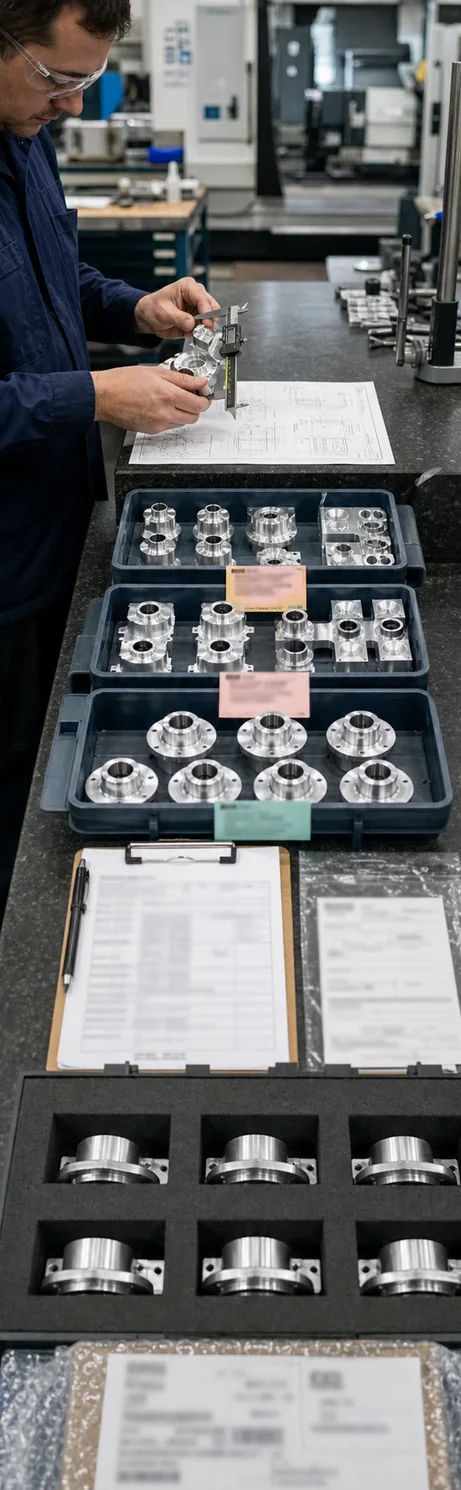
Inspector measuring CNC machined parts with inspection and lot traceability records
Inspection evidence and traceability records should be defined during RFQ.

Applications for Made-to-Drawing CNC Components

We evaluate projects based on drawing specifications and manufacturing feasibility across various demanding industries.

Industrial Machinery Automation & Robotics Motors & Motion Systems Automotive Equipment Electronics & Instruments Valves, Pumps & Fluid Control Molding & Tooling Support

See How Your Custom CNC Parts Are Made

LuckyHxs custom CNC machining factory tour video poster

Factory Visibility and Documents Available for Review

International buyer inspecting CNC machined parts at LuckyHxs factory Engineering discussion between client and LuckyHxs team Customer reviewing quality control processes in the factory Client viewing raw material storage and traceability system

We welcome direct communication and scheduled factory visits for engineering review and supplier audits.

Factory & Quality Support

Factory Access and Quality Documents for Your CNC Project

For custom CNC machining projects, factory evaluation and quality documentation should be aligned with the part’s function, critical features, material requirements, and production stage. Tell us what your supplier approval process requires, and we will confirm the applicable inspection records and project documents during quotation.

LuckyHxs inspector reviewing custom CNC machined parts against engineering requirements

Factory Communication & Visit

Communicate directly with our manufacturing team about part geometry, machining processes, inspection requirements, and repeat-production planning. Scheduled factory visits or supplier reviews can be discussed according to project needs.

Inspection Records

Depending on the agreed inspection scope, project records may include dimensional inspection results, first-article findings, thread gauge checks, runout measurements, or surface-finish data.

Material & Traceability Documents

If your project requires material documentation, batch identification, treatment records, or other traceability information, specify these requirements during the RFQ stage so availability and scope can be confirmed before production.

Document type, reporting format, inspection scope, and availability are confirmed according to the drawing, application, and quotation requirements. No certificate or document should be presented as standard unless it has been verified for the specific project.

Custom CNC Machined Parts Factory FAQ

What information do you need to quote a custom CNC part?
To provide an accurate quote, we require detailed 2D drawings (PDF) specifying dimensions, tolerances, and surface finishes, along with 3D CAD files (STEP, IGES) for programming. Additionally, please specify the material grade, required quantities (prototype and production), surface treatment, and any specific inspection or packaging requirements. Missing information may delay the quotation process.
Can you machine from both 2D drawings and 3D CAD files?
Yes, we utilize both. 3D CAD models are essential for CAM programming and understanding complex geometries, while 2D drawings act as the legal document defining critical tolerances, GD&T, threads, and surface finish requirements that cannot be fully captured in a standard 3D model. Both are highly recommended for accurate manufacturing.
What types of custom CNC parts can you manufacture?
We manufacture a wide variety of made-to-drawing components, including precision shafts, bushings, sleeves, pins, spacers, threaded inserts, custom fasteners, equipment housings, enclosures, and structural brackets. Our capabilities support various geometries depending on the selected machining process.
How do you choose between CNC turning and milling?
The choice depends on part geometry. CNC turning is ideal for cylindrical, symmetrical parts like shafts and bushings where the workpiece rotates. CNC milling is used for prismatic parts, flat surfaces, complex cavities, and off-axis holes where the cutting tool rotates. Complex parts often require turn-mill machining or multiple setups using both processes.
What materials are available for CNC machining?
We process a range of metals and engineering plastics, including Aluminum (6061, 6063, 7075), Stainless Steel (303, 304, 316L), Free-Machining Steel (1214, 1215), Brass (H59, C3604), and plastics like POM and PTFE. Final material grade availability is confirmed during the engineering review and quotation phase.
How much does a custom CNC machined part cost?
Cost is determined by raw material price, machining time, setup complexity, required tooling, tolerances, inspection requirements, and order volume. Prototyping incurs higher per-unit costs due to unamortized setup and programming, while volume production significantly reduces the unit price. We provide itemized quotes based on your specific drawings.
Can you support prototypes and repeat production?
Yes, we support the entire product lifecycle. We can manufacture small-batch prototypes for functional testing and design validation. Once approved, we can transition the project into repeat volume production, ensuring process stability and dimensional consistency across larger batches, subject to project review.
CUSTOM CNC PARTS RFQ

Request a Quote for Your Custom CNC Machining Parts

Send us your drawing and project requirements for a manufacturing review. We will evaluate the part geometry, material, quantities, critical features, surface requirements, and inspection needs before confirming the applicable machining route and quotation.

Information to Include

  • Latest 2D drawing or 3D CAD file
  • Material and grade
  • Prototype and production quantities
  • Critical dimensions or GD&T, threads and fits
  • Surface-finish requirements and target schedule

Drawing & Project Confidentiality

Your drawings, CAD files, and project information will be used only for quotation, manufacturability review, and project communication. If your project requires an NDA or a specific document-handling procedure, tell us before submitting sensitive files.

  • Project files used for quotation and engineering review
  • NDA requirements can be discussed before submission
  • Drawing revision and document scope confirmed per project

Direct Contact

Oem CNC Machining Parts RFQ

Fields marked with * are required. If the machining process or material is not yet confirmed, select "Not Sure" and provide your drawing for engineering review.

Highly Recommended

Supported formats: PDF, JPG, PNG, STEP, IGES, STL, DWG (Max 20MB)

Upload a File or drag and drop

Supported formats: PDF, JPG, PNG, STEP, IGES, STL, DWG (Max 20MB)