
CNC Turning Milling Parts for Complex Multi-Feature Components
LuckyHxs is a CNC turning milling parts manufacturer focused on custom, drawing-based rotational components that combine turned diameters with flats, slots, cross holes, radial threads, and other milled features. Each drawing is reviewed around functional datums, machining sequence, and repeat-production requirements.
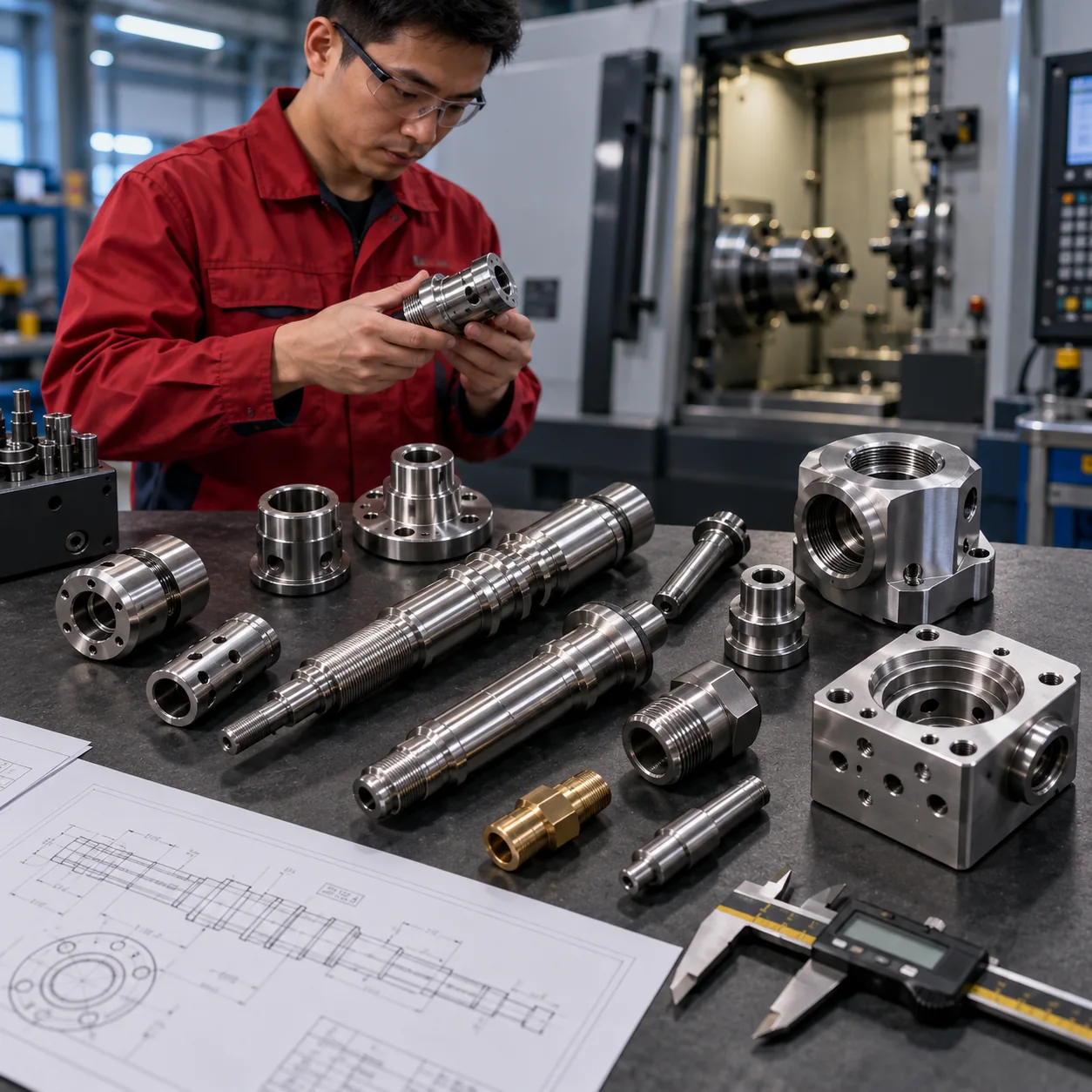
CNC Turning & Milling at a Glance
| Supply Type | Custom Made-to-Drawing Turn-Mill Parts |
|---|---|
| Part Geometry | Rotational Components With Milled / Radial / Off-Axis Features |
| Processes | CNC Turning / Milling / Turn-Mill / Drilling / Threading / Grooving / Cross Drilling |
| Typical Parts | Shafts / Fittings / Flanges / Valve Bodies / Pins / Sleeves / Sensor Bodies |
| Critical Features | Runout / Concentricity / Hole Position / Flat Position / Slot / Thread / Datum Relationship |
| Materials | Aluminum / Stainless Steel / Brass / Copper / Steel / Selected Plastics |
| Tolerance |
Standard Reference ±0.01 mm
Feature-specific tolerance capability depends on geometry, material, datum relationships, machining route and inspection requirements. |
Looking for finished CNC turning milling parts?
LuckyHxs manufactures custom parts to your drawings. We focus on controlling the relationship between turned and milled features. We do not sell turn-mill machines.
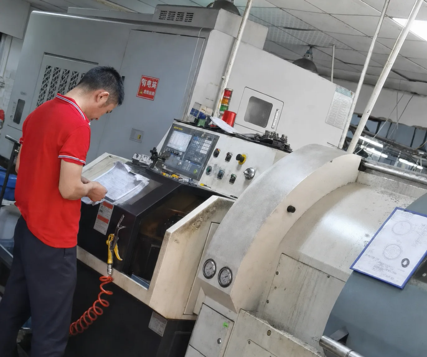
What Makes a CNC Turning Milling Part Different?
The engineering value is not just making the cuts—it is controlling both feature groups around the correct functional datum. Not every turned part requires milling, and not every milled part should be moved to turn-mill.
TURNING
- OD / ID
- Shoulder / Face
- Thread / Groove
MILLING / LIVE FEATURES
- Flat / Slot
- Cross Hole / Radial Port
- Bolt Pattern / Side Thread
MULTI-FEATURE PART
A single component where non-rotational features must maintain strict positional tolerance relative to the main rotational axis.
CNC Turning Milling Parts We Manufacture to Your Drawings
Categorized by rotational base geometry, milled feature integration, and functional application.
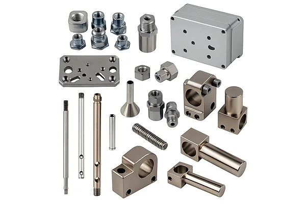
Turn-Mill Shafts & Spindles
A turned shaft may meet every diameter requirement and still fail in assembly if a milled flat, cross hole or slot is positioned incorrectly relative to the rotational axis.
Turning: OD, Shoulder, Thread
Milling: Flat, Keyway, Cross Hole
Watch: Flat-to-Axis Position
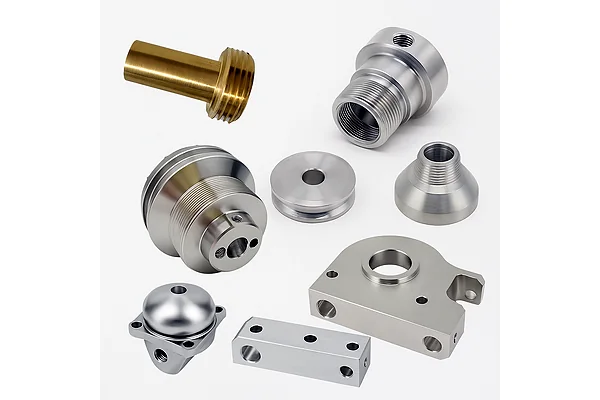
Turn-Mill Fittings & Adapters
A fitting can pass its thread gauge while still failing if the radial port or hex orientation is wrong relative to the main bore.
Turning: Bore, Internal/External Thread
Milling: Hex, Side Port, Radial Thread
Watch: Hex-to-Thread Relationship
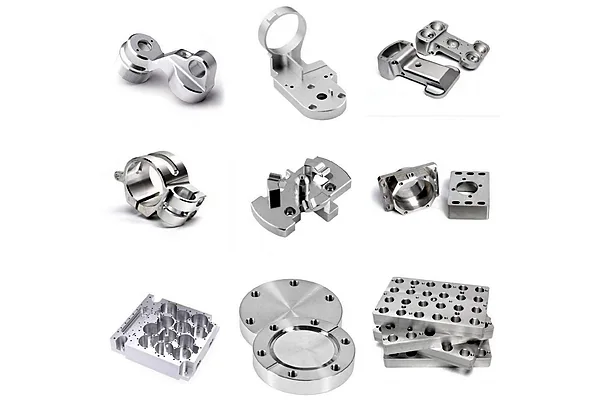
Turn-Mill Flanges & Hubs
The pilot diameter and bolt pattern must function as one datum system—not as two independent sets of dimensions.
Turning: OD, Pilot Diameter, Face
Milling: Bolt Pattern, Keyway
Watch: Pilot-to-Bolt Pattern
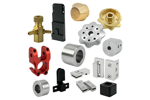
Turn-Mill Valve Bodies & Nozzles
A valve body can pass its OD and thread inspection while still failing if the radial port does not correctly intersect the main bore.
Turning: Precision Bore, Sealing Face
Milling: Radial Port, Side Thread
Watch: Cross-Hole Intersection
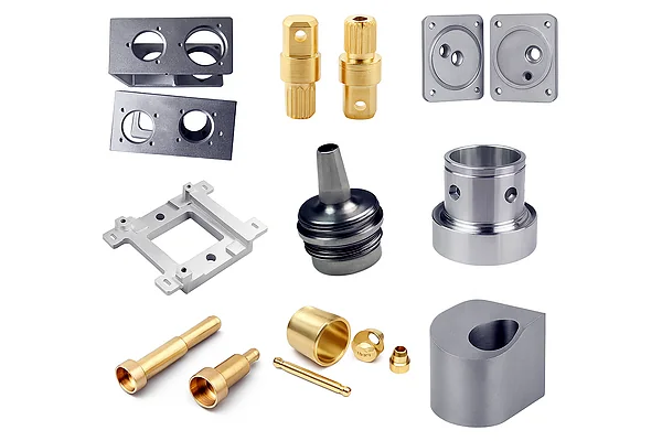
Turn-Mill Pins & Studs
Precision locating components requiring complex geometries like cross-holes, flats, or slots alongside tight-tolerance diameters.
Turning: Pin Diameter, Thread
Milling: Cross Hole, Milled Flat, Slot
Watch: Thread-to-Pin Axis
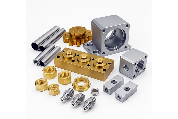
Turn-Mill Bushings & Sleeves
ID PASS + OD PASS + Hole PASS can still become Function FAIL if the radial port misses the internal groove or bore location.
Turning: ID, OD, Internal Groove
Milling: Side Hole, Radial Port
Watch: Port-to-Bore Relationship
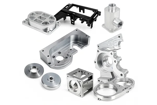
Sensor, Motor & Instrument Bodies
Cylindrical base housings requiring milled side features, connector openings, and precise mounting hole relationships.
Turning: OD, ID, Thread
Milling: Connector Opening, Mounting Hole
Watch: Thin Wall Distortion
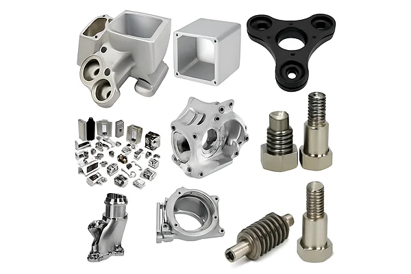
Complex Multi-Feature Components
The goal is not simply to perform more operations—it is to keep related features under fewer datum transfers when geometry allows.
Turning: Multi-Diameter, Bores
Milling: Off-Center Holes, Back-Side Features
Watch: Secondary Setup Risk
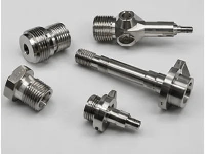
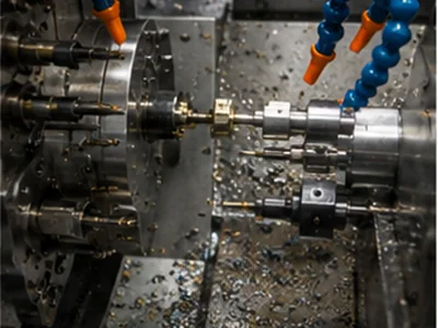
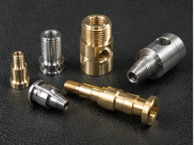
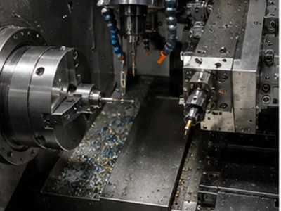
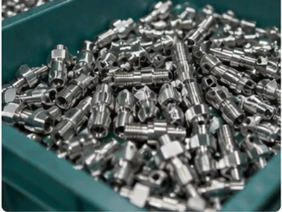
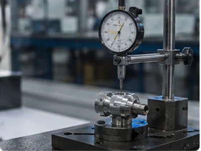
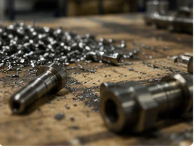
Multi-Feature CNC Turn-Mill Components
Which Parts Actually Need CNC Turning & Milling?
Choose the process from geometry and datum relationships—not from a marketing label.
OD + Thread
CNC Turning
Block + Pockets + Hole Pattern
CNC Milling
Small-Diameter Shaft
Swiss Evaluation
OD + Flat + Cross Hole + Radial Thread
Turn-Mill Evaluation
Flange + Pilot + Bolt Pattern
Combined Process Review
Materials for CNC Turning Milling Parts
Aluminum
6061 / 6063 / 6082 / 7075 where specified
Typical: Hubs, Adapters, Sensor Bodies, Lightweight Shafts
Buyer Watch: Thin Wall, Burr, Anodizing
Stainless Steel
303 / 304 / 316 / 316L
Typical: Fittings, Valve Components, Connectors
Buyer Watch: Work Hardening, Tool Wear, Thread
Brass
H57 / H59 / H62 / C3604 where applicable
Typical: Connectors, Adapters, Threaded Components
Buyer Watch: Thread, Burr, Surface
Copper
Pure Copper, Beryllium Copper
Typical: Electrical Connector Bodies, Contacts
Buyer Watch: Soft Surface, Built-Up Edge, Handling
Free-Machining Steel
1214 / 1215
Typical: Pins, Shafts, Studs, Hubs
Buyer Watch: Surface Protection, Rust Prevention
Engineering Plastics
POM, Nylon, PTFE, ABS where geometry is suitable
Typical: Insulators, Lightweight Fluid Bodies
Buyer Watch: Deformation, Clamping Force
Why Multi-Feature Parts Fail Even When Individual Dimensions Pass
Understanding the engineering risks of combining turning and milling.
Turning & Milling Features Lose Their Functional Datum Relationship
OD passes and Flat Width passes, but the flat is misaligned to the rotational axis, causing assembly failure.
Secondary Setups Create Datum Transfer Errors
Moving a part from a lathe to a mill introduces re-clamping variations, shifting critical hole patterns away from the pilot diameter.
Prototype Passes, but Multi-Feature Production Drifts
First article is perfect, but tool wear across different operations causes cross-hole positions to drift during batch runs.
Cross-Hole Intersections Retain Burrs & Chips
Flats, Slots & Key Features Are Misaligned to Axis
Front & Back Features Lose Alignment During Transfer
Thin-Wall Parts Distort After Combined Machining
Axial & Radial Threads Pass Gauging but Fail Assembly
Intersecting Features Create Hard-to-Control Burrs
Too Many Separate Operations Increase Cost, Lead Time & Process Risk
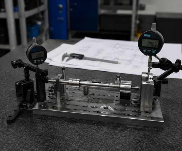
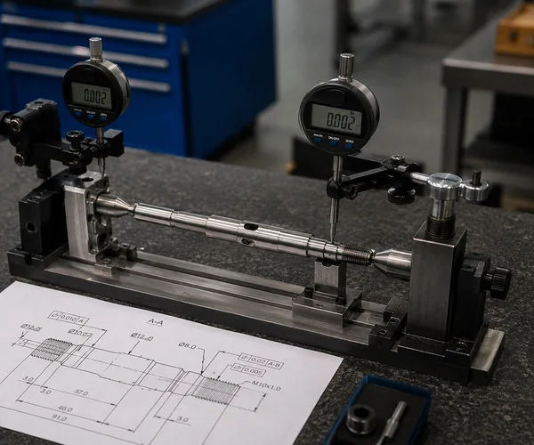
Turning & Milling Features Pass Individually but Lose Functional Alignment
The Challenge
Customers often receive parts where OD PASS, ID PASS, Thread PASS, and Flat Width PASS. Yet, the assembly FAILS. Why? Because the flat, cross hole, or slot is positioned incorrectly relative to the functional datum (like the pilot diameter or main bore).
Customer Consequence
The cross hole misses its target, the flat orientation is wrong, the radial port misses the main flow bore, or the bolt pattern shifts from the pilot. Inspecting dimensions in isolation is not enough.
LuckyHxs Approach
- Identify functional datum during drawing review
- Plan machining order around CTQ relationships
- Verify final assembly-critical geometry (Concentricity, Runout, Angular Orientation)
Secondary Setups & Part Transfers Shift Critical Datums
The Challenge
The traditional route (Turn → Remove → Re-Clamp → Re-Datum → Mill) increases datum transfer errors. Every re-clamping introduces angular error, chucking variation, and position accumulation.
Customer Consequence
Flats shift, radial holes rotate, slots lose their parallel relationship to the axis, and rear features lose alignment with front features.
LuckyHxs Approach
Fewer setups can mean fewer datum transfers. We evaluate whether related features can remain in fewer setups without falsely promising "One Setup Automatically Guarantees Accuracy."
- Define primary rotational datum
- Reduce unnecessary re-clamping
- Inspect Datum A/B/C relationships where specified
Prototype Passes, but Multi-Feature Production Drifts
The Challenge
First Article passes perfectly. But during the production batch, OD remains stable while cross-hole positions change, slot widths vary, radial thread positions shift, and burrs increase.
Why It Happens
Turning tool wear, drill wear, live tool conditions, thermal changes, and deburring variations across combined operations. Prototype approval does not automatically prove long-run multi-feature stability.
LuckyHxs Approach
- Tool Condition Monitoring
- In-Process Feature-Relationship Inspection
- Repeat-Order Requirement Retention
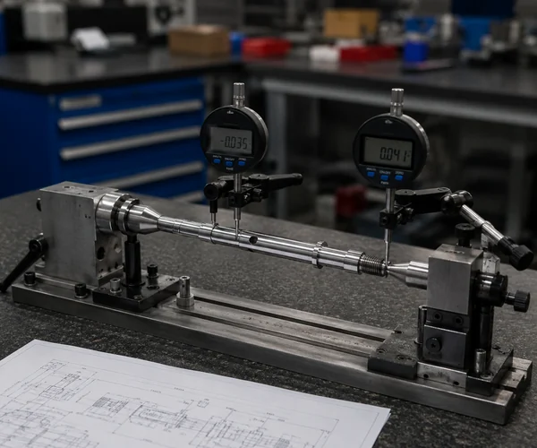
A Multi-Feature Part Should Be Inspected as One Functional Geometry
The most important tolerance is often the relationship between two features—not either feature by itself.
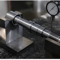
EXAMPLE 1: Shaft
Rotational Datum: Main OD
Related Feature: Milled Flat
Risk: Wrong angular orientation
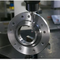
EXAMPLE 2: Flange
Rotational Datum: Pilot Diameter
Related Feature: Bolt Pattern
Risk: Assembly holes do not align
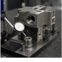
EXAMPLE 3: Valve Body
Rotational Datum: Main Bore
Related Feature: Radial Port
Risk: Port misses flow passage
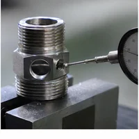
EXAMPLE 4: Adapter
Rotational Datum: Thread / Bore Axis
Related Feature: Hex / Side Hole
Risk: Wrong installation orientation
Cross Holes & Radial Features Need More Than a Diameter Check
Hole Diameter PASS ≠ Hole Intersection PASS. We focus on position, orientation, and intersection.
Cross Hole
Focus: Distance to Datum
Radial Port
Focus: Angular Orientation
Side Thread
Focus: Thread Depth & Burr
Off-Center Hole
Focus: True Position
Hole-to-Bore
Focus: Intersection Cleanliness
Hole-to-Groove
Focus: Alignment
Milled Flat
Focus: Flatness & Position
Side Slot
Focus: Parallelism to Axis
Intersecting Features Create Burrs That Standard Edge Breaking Can Miss
When a radial port meets a main bore, or a flat meets a thread, standard deburring is insufficient. Under-deburring leaves chips; over-deburring changes critical sealing edges.
Feature-Specific Deburring
- Cross Hole to Main Bore
- Radial Port to Groove
- Flat to Thread
- Cutoff Edge
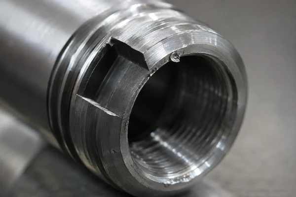
Front & Back Features Must Still Share the Same Part Datum
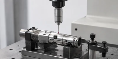
Front PASS + Back PASS does not automatically mean Front-to-Back Relationship PASS.
Typical Transfer Risks
- • Back Feature Offset
- • Back Bore Concentricity
- • Overall Length Variation
- • Surface Clamping Marks
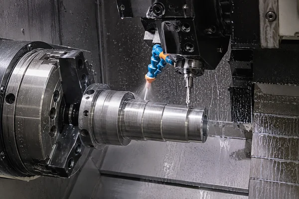
Thin Cylindrical Parts Can Distort When Turning and Side Milling Are Combined
Machining sequence matters when a cylindrical wall becomes thin. Before side machining, roundness passes. After milling a flat or slot, the bore can become oval, or the wall deflects.
Affected Parts
Thin Sleeves, Connector Shells, Sensor Bodies, Thin Hubs, Lightweight Valve Bodies.
LuckyHxs reviews wall thickness, plans turning/milling sequences to minimize radial force, and inspects roundness in the free-state geometry.
CNC Turn-Mill Capabilities for Multi-Feature Rotational Parts
Machine configuration is selected according to drawing requirements. Use the simplest stable machining route that maintains relationships.
*Where supported by geometry and machine configuration.
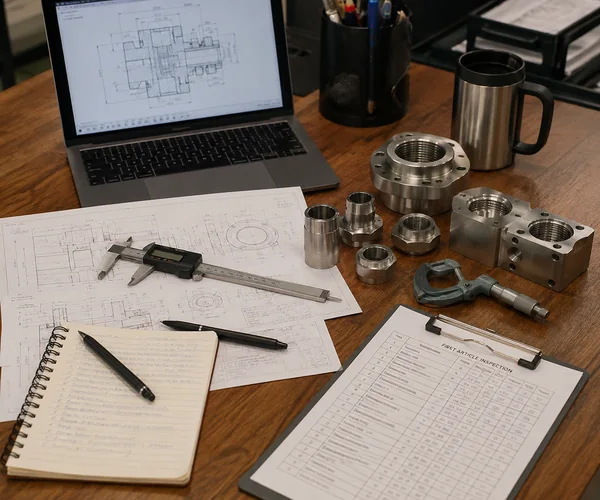
Inspect Turn-Mill Parts Beyond Individual Dimensions
- Drawing Review
- Material Confirmation
- Functional Datum Identification
- Turning / Milling Feature Classification
- Process & Setup Planning
- First Article Verification
- Turning Feature Inspection
- Milling Feature Inspection
- Feature-Relationship Inspection
- Burr / Intersection Review
- Final Batch Verification
- Repeat-Order Requirement Retention
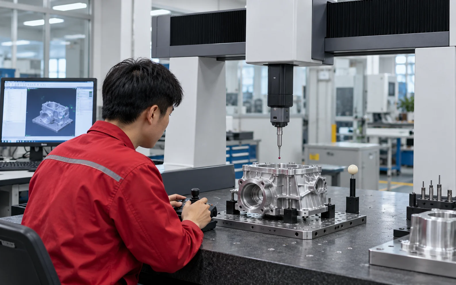
Inspection method (CMM, Optical, Gauge) is selected according to drawing, feature geometry, and tolerance requirements.
Where CNC Turning Milling Parts Are Used
Industrial Automation
Shafts with flats, locating pins.
Robotics & Motion
Precision hubs, coupling components.
Motors & Drives
Motor shafts, end housings.
Fluid Control
Valve bodies, ported sleeves.
Sensors & Instruments
Cylindrical sensor bodies.
Electronics
Connector bodies, adapters.
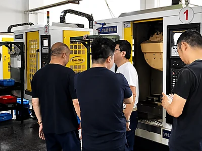
A CNC Manufacturing Partner You Can Verify
Certificates & Compliance Documents
Documents available upon project requirement.

What Are CNC Turning Milling Parts?
CNC turning milling parts are custom components that combine rotational base features (normally produced by turning) with non-rotational or off-axis features (produced through milling, drilling, or live-tool operations).
Typical Turning Features
- OD / ID
- Face / Shoulder
- Thread / Groove
Typical Milling Features
- Flat / Slot
- Cross Hole / Radial Hole
- Bolt Pattern / Side Thread
Why Combine the Processes?
The goal is not simply to machine faster. The engineering value lies in controlling Feature Relationships. By combining processes or carefully managing the machining sequence, manufacturers reduce datum transfers. This consolidation improves the positional accuracy between the rotational axis and the milled features, which is critical for complex geometries like ported valve bodies or cross-drilled shafts.
What Buyers Should Send for Quote:
2D Drawing, 3D CAD, Material, Quantity, Critical Datums, Threads, Hole Positions, Surface Finish, and Inspection Requirements.
Which Precision Parts Benefit from Combined CNC Turning & Milling?
Not all precision parts need turn-mill. Turn-mill is valuable when rotational and off-axis features have important positional relationships. Here are 5 criteria to evaluate your drawing:
- Does the part have a rotational base geometry (OD, ID, Bore)?
- Does it also have off-axis features (Flat, Slot, Cross Hole)?
- Do the turning and milling features share a critical datum?
- Would multiple setups create position stack-up errors?
- Is repeat production important enough to justify process consolidation?
How Do You Choose a CNC Turning Milling Parts Manufacturer?
The Buyer Checklist
- 1. Can they read turning and milling features as one datum system?
- 2. Can they identify which features need the same setup?
- 3. Can they control runout and concentricity?
- 4. How are cross holes and radial features inspected?
- 5. How are flats, slots and angular features positioned?
- 6. How are front and back features controlled?
- 7. How are radial and axial threads inspected?
- 8. How are internal cross-hole burrs removed?
- 9. How are thin-wall cylindrical parts protected from distortion?
- 10. How do they control tool wear across combined operations?
- 11. How do they move from first article to repeat production?
- 12. Can they recommend Turning, Milling, Swiss or Turn-Mill based on the drawing?
LuckyHxs supports drawing review, CNC turning, milling, turn-mill evaluation, material confirmation, first-article verification, and repeat production according to project requirements.
Frequently Asked Questions About CNC Turning Milling Parts
What are CNC turning milling parts?
What is the difference between CNC turning, CNC milling and turn-mill machining?
Which parts are best suited for CNC turning and milling?
Can cross holes, flats and slots be machined on turned parts?
How do you control the position between turned and milled features?
Can you machine front and back features?
How do you remove burrs from cross-hole intersections?
What materials can be used for CNC turning milling parts?
How much do CNC turning milling parts cost?
What information do you need for a quote?
Need Turning and Milling Features to Work as One Geometry?
Send your 2D/3D drawing, material, quantity, critical datums, turned diameters, cross holes, slots, flats, threads, front/back features, surface finish and inspection requirements. Our team will review whether CNC turning, milling, Swiss or turn-mill machining is the most suitable route before quotation.
WHAT WE REVIEW BEFORE QUOTATION
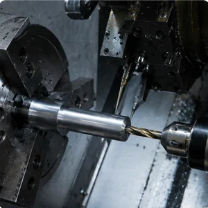
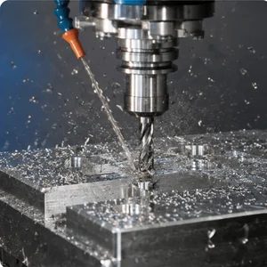
For parts with turned and milled features, we assess critical diameters, cross features, datums, and mating geometry to determine the machining process.
1. Turning Datums
Critical OD, ID, shoulders and axial reference surfaces.
2. Cross Features
Cross holes, flats, slots, side threads and milled pockets.
3. Concentricity & Runout
Relationships between turned diameters and rotating features.
4. Feature Position
Location of holes, slots and milled features from functional datums.
5. Setup Strategy
Whether turning and milling can be completed in one setup or require secondary operations.
6. Inspection Plan
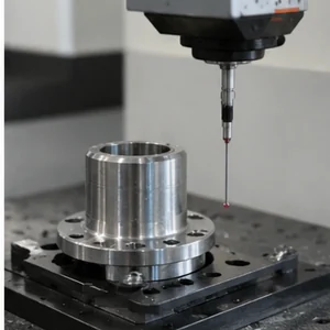
How critical diameters, position, runout and mating features will be verified.