
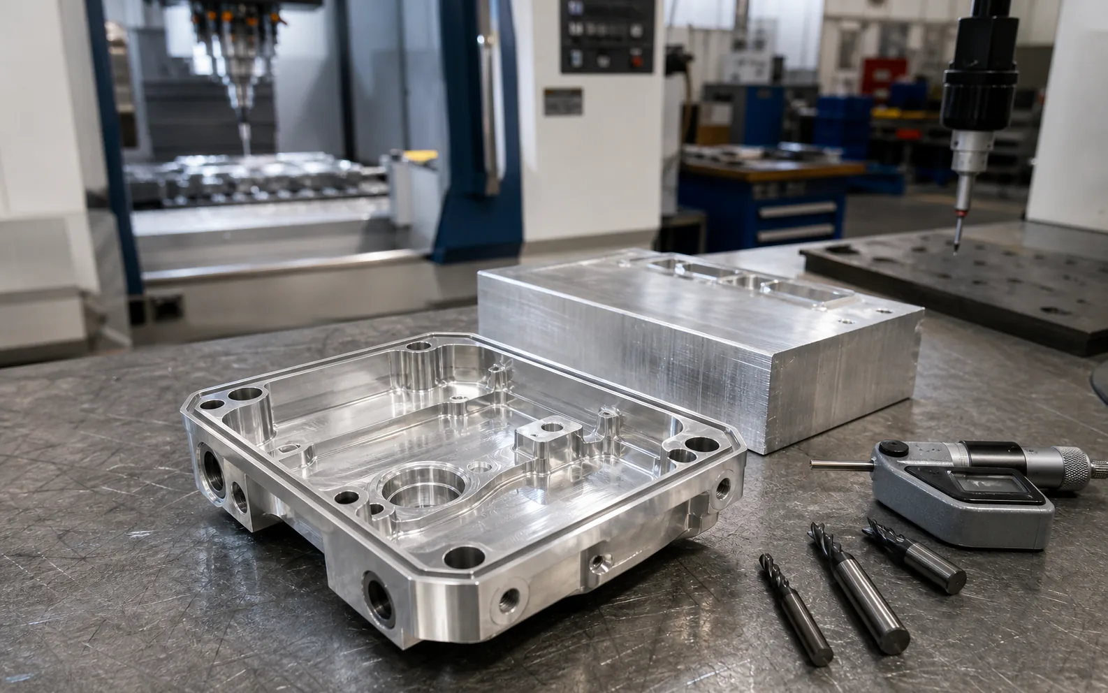
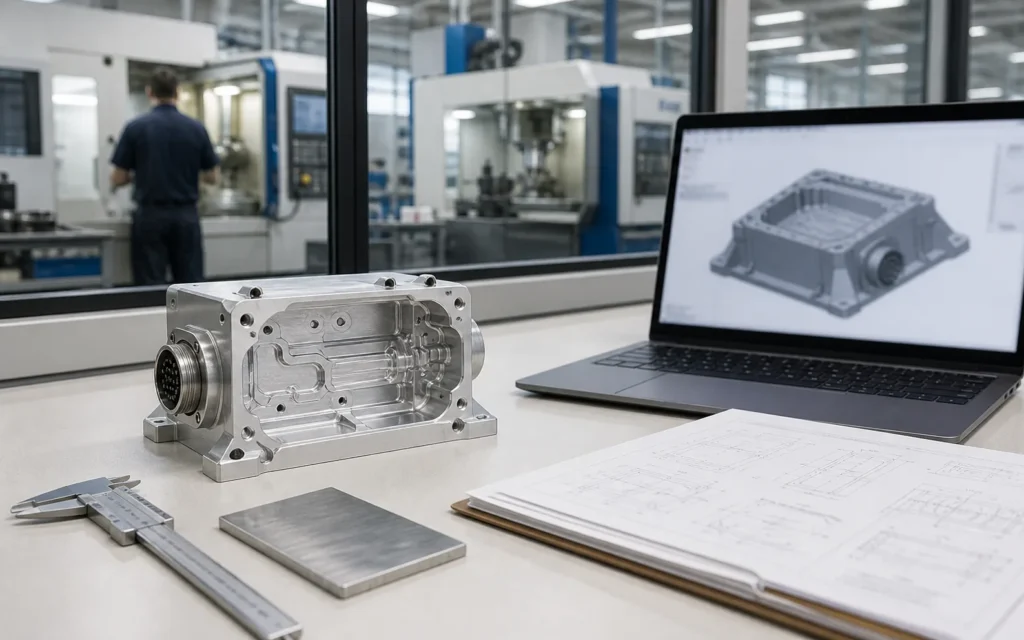
This aerospace sensor enclosure project shows how LuckyHxs supports custom CNC milling parts for buyers who need machined housings, thin-wall features, mounting interfaces and surface-finished components made from customer drawings. As a CNC milling parts supplier and CNC machining parts factory, LuckyHxs focuses on drawing review, material selection, machining sequence, finishing control and inspection planning before production.
For aerospace sensor components, reducing weight is only one part of the challenge. The enclosure still needs to maintain accurate interfaces, clean machined edges, and reliable fit with the components assembled around it.
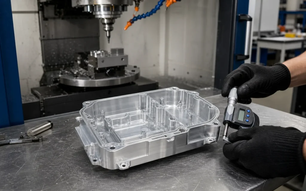
In this project, LuckyHXS was asked to manufacture a 7075 aluminum aerospace sensor enclosure with strict weight requirements and demanding burr control.
The part was produced by 5-axis CNC milling, with selected critical features controlled to ±0.004 mm. Final verification combined CMM inspection and 100% visual inspection.
For confidentiality, the customer name and drawing dimensions are not disclosed. The manufacturing challenges, process decisions, and verified production results described below reflect the project requirements.
Project Snapshot
Application: Aerospace sensor enclosure
Material: Aluminum 7075
Main Process: 5-axis CNC milling
Primary Constraint: Strict weight limits and burr control
Inspection: CMM + 100% visual inspection
Verified Result: Selected critical features controlled to ±0.004 mm
The Customer Challenge
The customer was not simply looking for a supplier that could machine an aluminum housing.
The enclosure had to satisfy several requirements at the same time:
- Keep the finished component lightweight.
- Maintain the dimensional relationships required for sensor assembly.
- Prevent burrs from remaining around machined edges and openings.
- Produce repeatable parts rather than a single acceptable prototype.
- Protect critical mounting and mating features throughout the machining process.
Aluminum 7075 was selected for the component, giving the project a strong strength-to-weight foundation while still requiring careful process control during precision milling.
The most important manufacturing question was therefore not:
“Can this part be machined?”
It was:“Can the same critical geometry be reproduced consistently without adding unnecessary material, secondary rework, or burr-related assembly risk?”
Project Timeline
Stage 1 — Drawing and Manufacturing Review
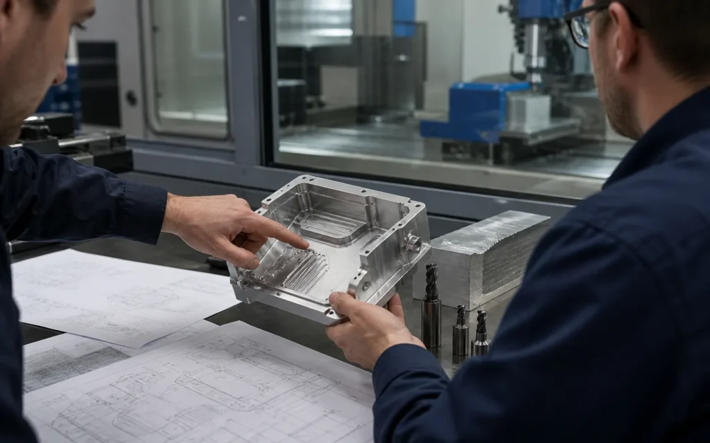
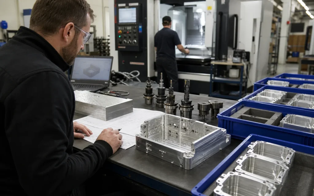
The project started with an engineering review of the customer drawing and 3D model.
Instead of treating every dimension as equally critical, our team first identified the features that directly affected:
- assembly position,
- mounting relationship,
- mating interfaces,
- enclosure fit,
- and final functional alignment.
These features became the main control points for machining and inspection.
The review also focused on areas where burrs could be difficult to detect or remove after machining.
This allowed the process plan to be built around the actual assembly risks rather than simply following the drawing feature by feature.
Stage 2 — 5-Axis Machining Strategy
A 5-axis CNC milling process was selected for the enclosure.
The objective was to machine multiple faces and critical relationships with fewer unnecessary repositioning steps.
Reducing repeated workholding changes helped the team maintain a more stable relationship between features located on different faces of the enclosure.
Tool selection and machining sequences were also planned with two priorities:
- remove enough material to achieve the required lightweight structure;
- retain stable support around critical features during machining.
Instead of aggressively removing all material at once, machining was sequenced so that important areas remained supported until the appropriate finishing stage.
Burr Control Was Treated as a Functional Requirement
For this aerospace sensor enclosure, burr removal was not considered a cosmetic final step.
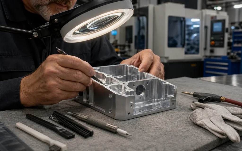
A small remaining burr around an opening, mounting feature, or internal edge can interfere with assembly even when the measured dimensions are technically within tolerance.
For that reason, deburring was integrated into the manufacturing route.
After machining, the enclosure received targeted edge inspection rather than relying only on a general visual check.
Operators paid particular attention to:
- machined openings,
- pocket transitions,
- mounting features,
- intersecting edges,
- and areas that could contact mating components.
Every finished enclosure then passed 100% visual inspection.
Dimensional Verification with CMM
The dimensional inspection strategy concentrated on the features identified as critical during the initial engineering review.
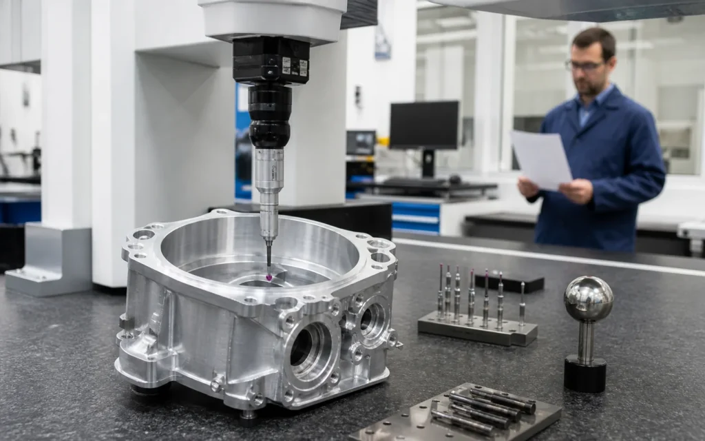
A coordinate measuring machine was used to verify the required relationships rather than relying only on handheld gauges.
For selected critical features, the process achieved control to:
±0.004 mm
This result was especially important because the customer’s concern was not only whether one first article could meet the drawing.
The greater concern was whether those important features could remain stable as the project moved toward repeat production.
From First Article to Repeat Production
Once the first machined parts passed dimensional and visual verification, the process was not immediately treated as finished.
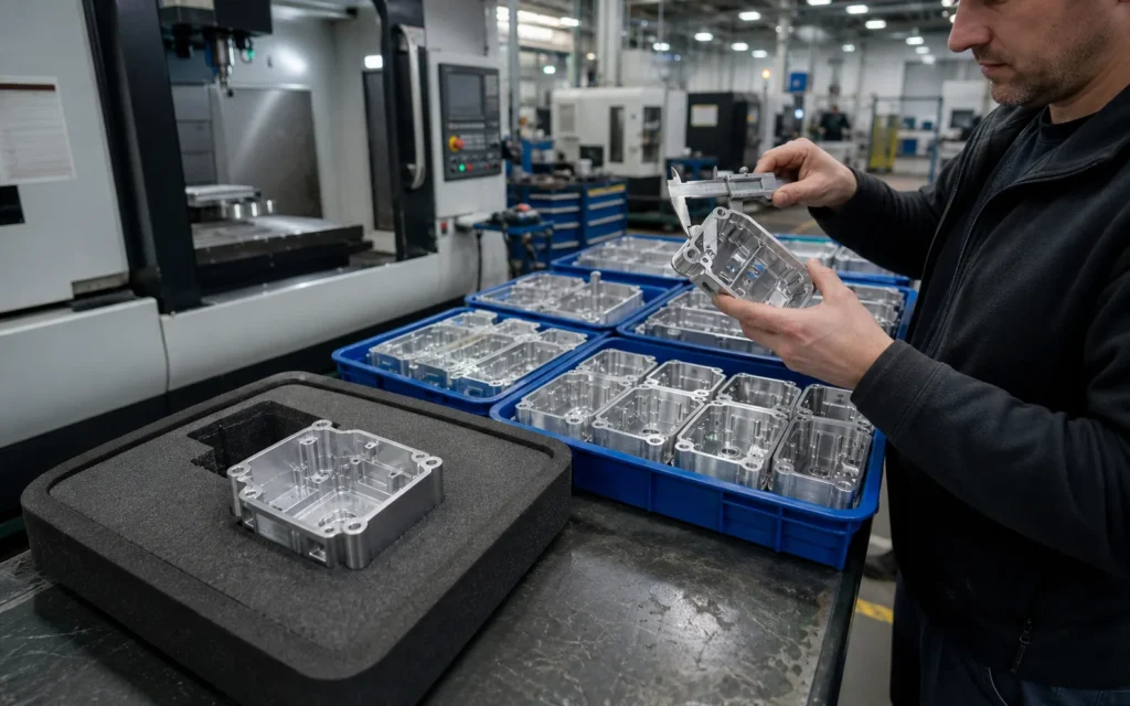
The same machining sequence, workholding approach, inspection points, and burr-control requirements were retained for the next production stage.
This created a repeatable manufacturing baseline.
The customer could evaluate actual machined parts rather than relying only on a machining capability statement.
The cooperation progressed through a practical sequence:
Drawing Review → Process Planning → First Article Machining → CMM Verification → Burr Inspection → Customer Validation → Repeat Production
The project moved forward after the critical dimensional and surface requirements had been demonstrated on real parts.
What Made the Project Work
The key was not one machine or one inspection report.
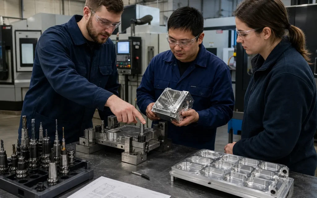
The result came from connecting the full process:
Engineering review before machining
Critical features were identified before production began.
5-axis CNC milling
Multiple machining relationships could be managed within a more controlled setup strategy.
Controlled material removal
The lightweight requirement was balanced against machining stability.
Burr management
Edge condition was treated as an assembly requirement, not simply a visual issue.
CMM verification
Selected critical dimensions and relationships were checked using appropriate measurement equipment.
100% visual inspection
Finished parts were individually checked for visible burrs and machining defects before release.
Final Result
The finished 7075 aluminum aerospace sensor enclosure met the project’s lightweight and burr-control requirements while selected critical features were maintained to ±0.004 mm.
More importantly, the customer received a manufacturing route that could be carried forward from first article validation into repeat production.
For LuckyHXS, this project demonstrated an important principle in aerospace CNC machining:
Precision is valuable only when it can be repeated.
Need a Similar Aerospace CNC Part?
If your aerospace enclosure, bracket, housing, or structural component includes critical datums, multi-face machining, low-weight geometry, or strict burr requirements, send us your drawing and 3D model.
Our engineering team can review the material, tolerance, machining strategy, inspection requirements, and production quantity before quotation.