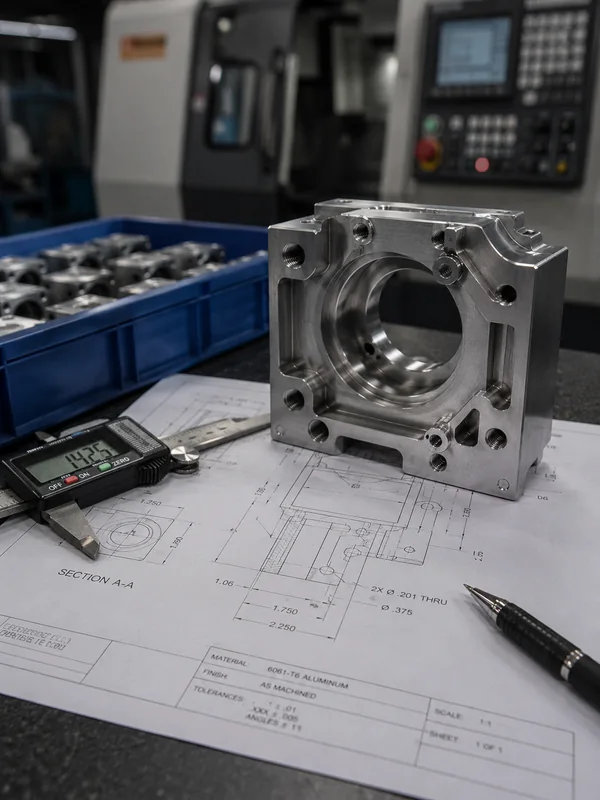
Precision Deburring Services for CNC Machined Parts
LuckyHxs provides precision deburring support for custom CNC machined parts where edge condition affects assembly, fit, threads, bores, internal passages or functional surfaces. We review external edges, cross-hole intersections, internal bores, threads, part-off features and small precision geometry according to the drawing and final part requirements.
The goal is not simply to make every edge smooth. Precision deburring must remove unwanted burr material without changing the feature that makes the part work.
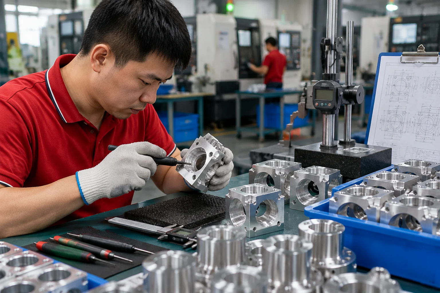
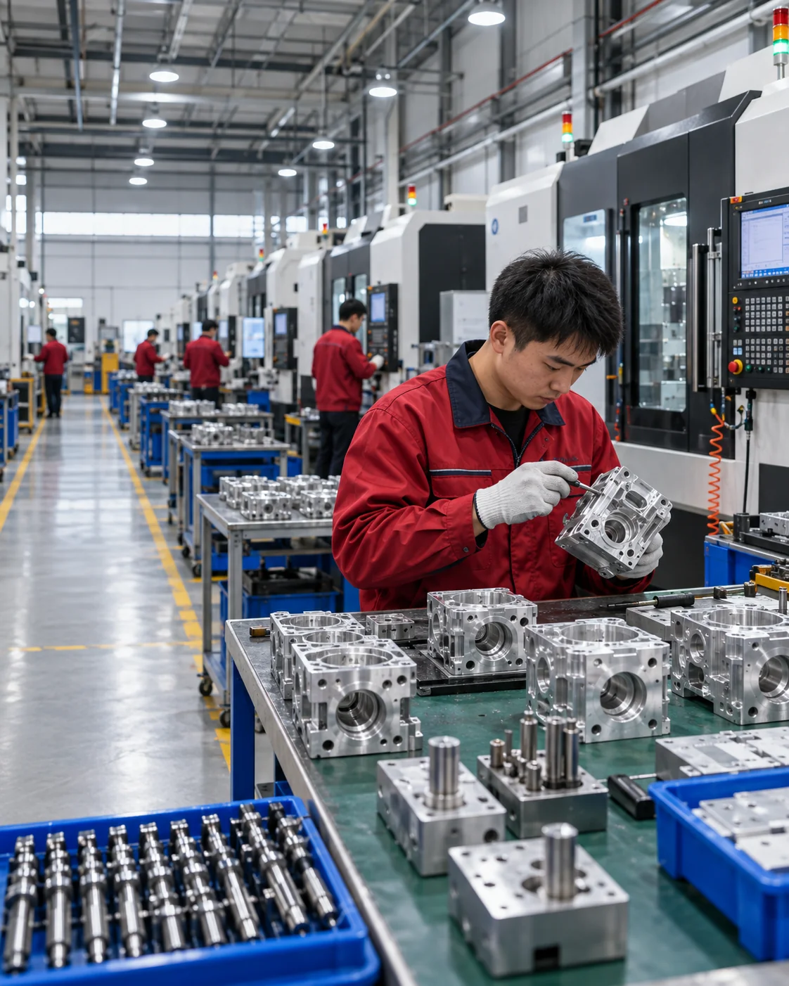
Precision Deburring From a CNC Parts Manufacturer
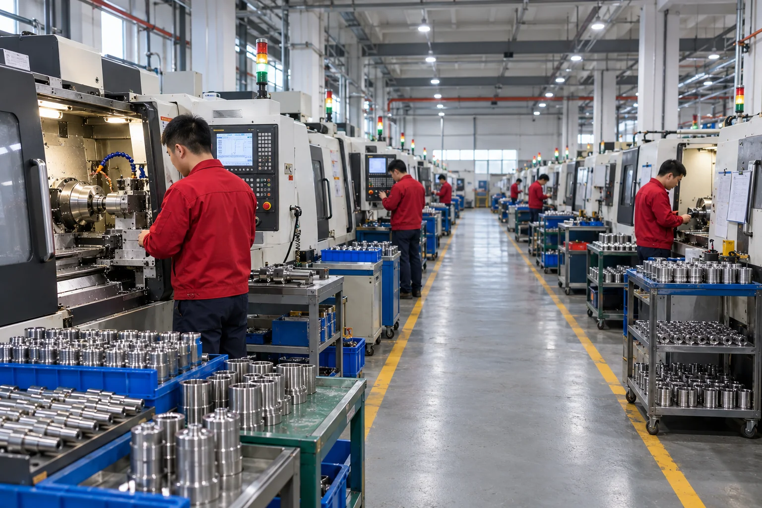
LuckyHxs manufactures precision CNC components directly from customer drawings and treats deburring as part of the complete machining workflow. Burr location, functional edge requirements, threads, bores, mating surfaces and final inspection should remain connected to the same drawing—not handled as an unrelated cosmetic step.
Integrated Workflow
Deburring Is Not the Same as Making Every Edge Round
The goal is to remove unwanted material while preserving the drawing-defined feature. Remove the Burr Without Removing the Feature.
Remove the Burr
Eliminate unwanted raised material, sharp projections, and loose chips left by the cutting tool.
Control the Edge
Produce the exact drawing-defined final edge condition, whether it is a controlled break, chamfer, or radius.
Protect the Function
Ensure deburring does not alter datums, sliding fits, thread entries, or critical sealing surfaces.
Precision Deburring Services for CNC Machined Features
Categorized by burr location and functional edge requirement.
Precision Edge Deburring & Controlled Edge Break
For external edges, machined corners, and shoulder edges on brackets and housings.
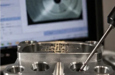
Cross-Hole & Intersecting-Hole Deburring
For internal intersections, side ports, and cross-drilled passages in valve bodies.
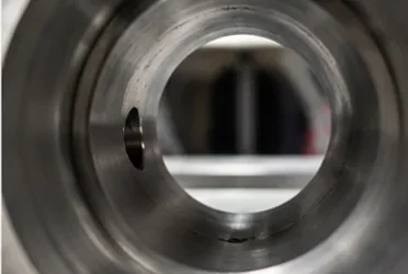
Internal Bore & Deep-Hole Deburring
Addressing bore entrance/exit, internal shoulders, and deep-hole burrs in sleeves.
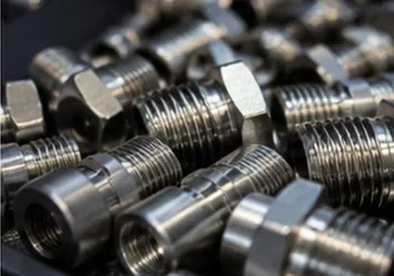
Thread, Thread-Entry & Thread-Exit Deburring
Managing first thread burrs, entry chamfers, and blind thread chips on studs/inserts.
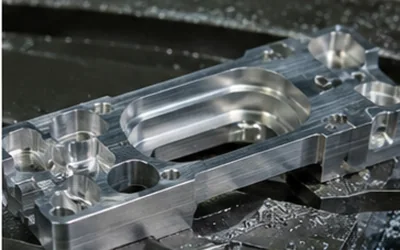
Turned, Swiss & Part-Off Burr Removal
Resolving part-off burrs, center pips, and groove edges on small precision shafts.
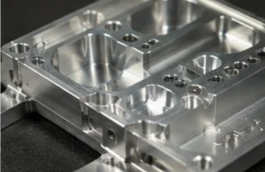
Milled Pocket, Slot & Complex-Edge Deburring
Cleaning pocket edges, slots, and internal corners on multi-axis milled housings.
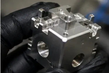
Micro-Feature & Small Precision Part Deburring
Handling small holes, fine threads, and miniature grooves on connector pins.
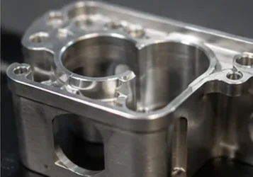
Thin-Wall, Delicate & Functional-Surface Deburring
Protecting roundness and sealing faces on thin sleeves and delicate rings.
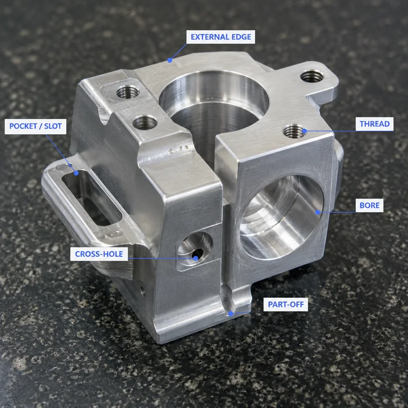
Where Is the Burr—and What Does That Edge Do?
The same burr size can have very different consequences depending on where it is located.
-
EXTERNAL EDGE: Handling / Assembly risk
-
CROSS-HOLE: Internal Interface / Fluid passage obstruction
-
BORE: Guide / Fit / Passage interference
-
THREAD: Fastening entry block / Galling risk
-
PART-OFF: Seating / End Condition failure
-
POCKET / SLOT: Mating Geometry interference
Burr Formation & Deburring Strategy Change With Material
Different alloys require different cutting, brushing, or abrasive pressure to prevent surface damage.
Aluminum (6061, 7075)
Typical: Housings, Brackets.
Stainless Steel (304, 316L)
Typical: Shafts, Valve Components.
Brass (H59, C3604)
Typical: Inserts, Connectors, Fittings.
Copper
Typical: Connector components.
Free-Machining Steel (1215)
Typical: Pins, Studs, Bushings.
Engineering Plastics (POM, PTFE)
Typical: Insulators, Seals.
Choose the Deburring Method From the Burr Location & Feature Geometry
The method should follow the feature—not the marketing name.
| Method | Good For | Status |
|---|---|---|
| CNC Programmed Chamfer / Edge Break | Accessible drawing-defined edges incorporated into the machining route. | Standard Route |
| Manual Precision Deburring | Selective/complex accessible features, small batches, delicate edges. | [CONFIRM AVAILABILITY] |
| Rotary / Cross-Hole Tooling | Intersecting bores requiring correct geometry and access. | [CONFIRM TOOLING] |
| Vibratory Deburring | Batch finishing for accessible edges. Risk: Touches all surfaces. | [CONFIRM AVAILABILITY] |
| Thermal Deburring (TEM) / ECM / AFM | Industry Method Comparison Only. Suitable for complex internal networks where applicable. Not automatically available unless confirmed. | |
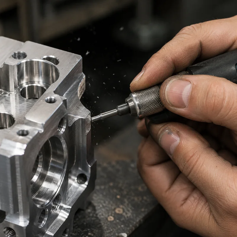
Controlled Edge Break Means Removing the Burr Without Losing the Feature
Burr Removed ≠ Edge Geometry Controlled.
Simply making an edge smooth is not enough for precision parts. External edges, datums, shoulders, hole edges, and pocket edges must meet the drawing requirement—whether that is a controlled edge break, a defined chamfer, a specific radius, or a strict instruction to keep the edge sharp.
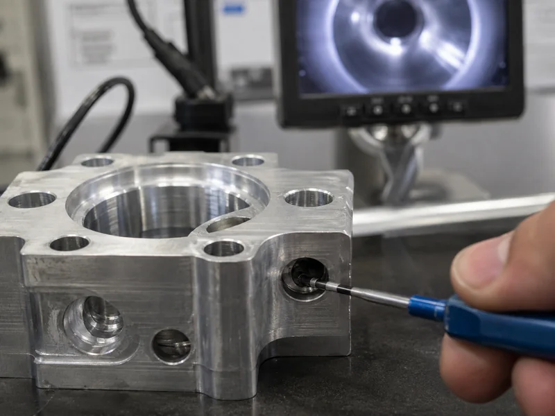
Hidden Cross-Hole & Internal Burrs Need a Different Review
Hole Diameter PASS ≠ Intersection Condition PASS.
Main bores, cross holes, radial ports, deep bores, internal shoulders, and internal grooves present significant access challenges. A visible external edge may look clean, while a critical rolled burr or chip remains hidden inside the bore intersection, threatening assembly, sealing, or fluid flow.
Threads, Part-Off Edges & Micro Features Magnify Small Burr Problems
Thread Features
First thread burrs, entry chamfers, exit burrs, and blind thread chips can block assembly even if the thread gauge passes.
Thread Gauge PASS ≠ Burr-Free Assembly Interface.
Part-Off Edges
Turned and Swiss parts often suffer from cutoff burrs, center pips, or groove edge burrs that prevent proper seating.
Cutoff Complete ≠ Finished Part Complete.
Micro Features
Small holes, tiny shoulders, and fine grooves require deburring pressure that scales with the feature—not the tool.
A Small Burr Can Be a Large Defect.
Why CNC Parts Fail Even After They Have Been "Deburred"
The 10 most common procurement risks when deburring is treated as an afterthought.
1. The Burr Is Removed, but the Functional Edge Geometry Is Changed
2. External Edges Clean, but Cross-Hole Burrs Remain
10. Prototype Deburring Passes, but Edge Condition Drifts Across Production Batches
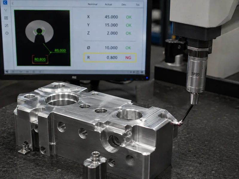
The Burr Is Removed, but the Functional Edge Geometry Is Changed
Burr Removed ≠ Edge Geometry Controlled.
The goal is not simply to make the edge smooth. The goal is to remove unwanted burr material while preserving the drawing-defined feature.
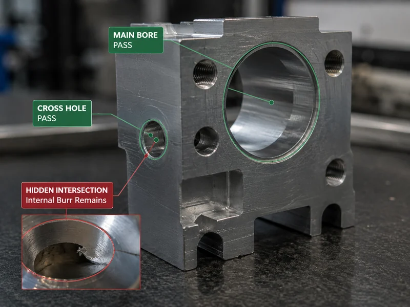
External Edges Look Clean, but Burrs Remain at Cross-Hole Intersections
Hole Diameter PASS ≠ Intersection Condition PASS.
Cross-hole burrs are difficult because the visible outside edge may look complete while the critical burr sits inside the bore intersection.
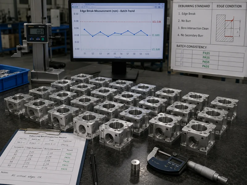
Prototype Deburring Passes, but Edge Condition Drifts Across Production Batches
Sample Deburring Approval ≠ Automatic Batch Edge Consistency.
Machining tool wear, burr formation changes, deburring tool condition, operator variation, and material lot differences can cause final edge conditions to drift during production.
- Critical Edge Identification retention
- Machining Burr Source Review per batch
- Feature-Specific Treatment controls
- Batch Verification & Repeat-Order retention
"Deburr All Edges" Is Not Always a Complete Edge Specification
Undefined Deburring Requirement = Undefined Acceptance Standard. Define the Edge Before Defining the Method.
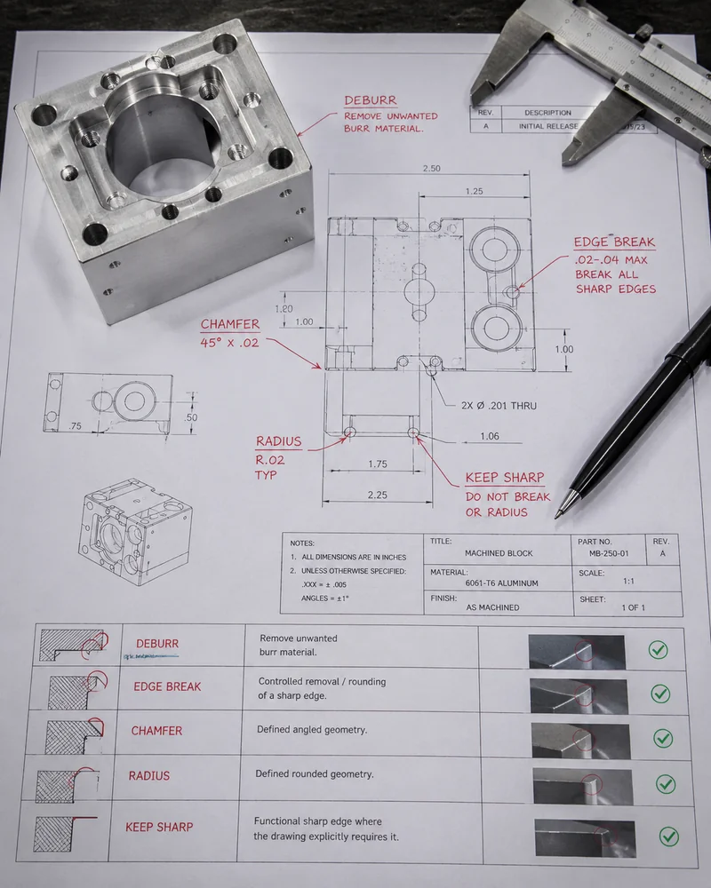
DEBURR
Remove unwanted burr material.
EDGE BREAK
Controlled removal / rounding of a sharp edge.
CHAMFER
Defined angled geometry.
RADIUS
Defined rounded geometry.
KEEP SHARP
Functional sharp edge where the drawing explicitly requires it.
Drawing edge requirements may reference standards such as ISO 13715 where applicable to indicate undefined shape edges.
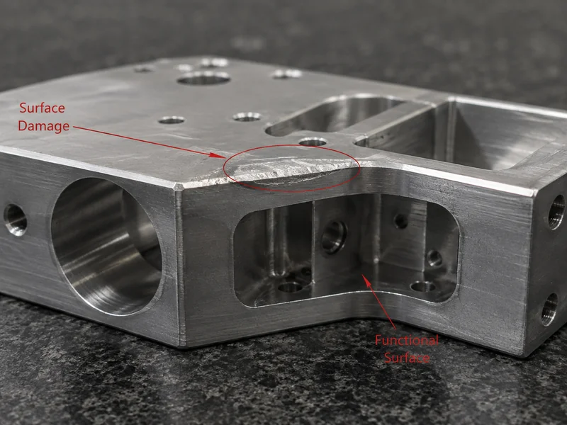
A Burr-Free Part Can Still Fail if the Functional Surface Is Damaged
Burr-Free ≠ Distortion-Free.
Excessive force, abrasive contact, poor support, or repeated handling during deburring can destroy thin-wall sleeves, sensor bodies, sealing faces, datums, and bearing surfaces. Local material removal can shift roundness or flatness.
Inspect the Edge the Same Way the Drawing Uses It
Inspection Method Should Follow the Burr Location & Edge Function.
EXTERNAL EDGE
Visual / tactile review where appropriate.
THREAD
Thread gauge + entry/exit visual review.
CROSS-HOLE
Internal intersection review according to access.
CONTROLLED CHAMFER
Dimensional inspection where drawing-defined.
100% visual inspection before shipment. Critical holes reviewed separately where applicable according to project requirements.
From Machining Burr to Assembly-Ready CNC Component
Good deburring begins with controlling how the burr is created—not only removing it afterwards.
Precision Deburring Applications
Fluid Control
Valve Body / Cross-Hole Burr
Motor System
Shaft / Part-Off Burr
Connectors
Small Pin / Micro Burr
Robotics
Bracket / Pocket Edge
Sensors
Housing / Thin Wall
Auto & EV
Manifold / Milled Edge
12-Step Manufacturing Workflow
- Drawing Revision Review
- Material Confirmation
- CNC Process Selection
- Critical Edge Identification
- Burr Source Review
- Machining
- Pre-Deburr Inspection
- Feature-Specific Deburring
- Internal Hole/Thread Review
- Final Edge & Surface Inspection
- Cleaning / Surface Protection
- Batch Verification & Packing
A CNC Manufacturing Partner You Can Verify
Certificates & Compliance Documents for precision manufacturing.
What Is Deburring in CNC Machining and Why Does It Matter?
Deburring is the manufacturing process of removing unwanted raised material, sharp projections and loose burrs left on a part after machining operations such as milling, turning, drilling, tapping or cutting.
What is a Burr?
A burr is unwanted material that remains beyond the intended machined edge after material removal.
Where Do CNC Burrs Form?
- Hole Exit & Cross-Hole Intersection
- Thread Entry / Exit
- Part-Off Edge
- Pocket, Slot, Shoulder, Internal Bore, Groove
Why It Matters
Deburring is not only about making a part safer to touch. For precision CNC parts, it is also about protecting functional geometry. Burrs interfere with assembly, sliding interfaces, sealing, thread entry, internal cleanliness, and handling safety.
Deburring vs Chamfering
Deburring: removes unwanted burr material.
Chamfering: creates a defined angled feature.
Edge Breaking: creates a controlled non-sharp condition.
What Are the Main Deburring Methods for CNC Machined Parts?
There is no single deburring method that is ideal for every CNC part. The method depends on Burr Location, Feature Geometry, Material, Edge Requirement, Accessibility, Part Size, Quantity, and Functional Surface Risk.
How Do Deburring Tools Work?
Different deburring tools remove burrs through controlled cutting, brushing, abrasion, thermal energy or electrochemical action. The correct tool depends on the burr and geometry—not simply the part material.
Manual Precision Deburring
Good for: Selective / complex accessible features. Risk: Operator variation / over-removal.
CNC Programmed Chamfer / Edge Break
Good for: Accessible drawing-defined edges. Benefit: Geometry can be incorporated into machining where suitable.
Rotary / Cross-Hole Tool
Good for: Intersecting bores. Requires: Correct geometry / access.
Vibratory Deburring
Good for: Batch finishing / accessible edges. Risk: Touches multiple surfaces.
Note: Advanced industry methods like Thermal Deburring (TEM), Electrochemical Deburring (ECM), Abrasive Flow Machining (AFM), and Robotic Deburring exist for specialized applications. Choose the Method Around the Burr Location—not the Marketing Name.
How Should Deburring & Edge Break Be Specified on a CNC Drawing?
A general note such as "DEBURR ALL EDGES" may communicate that burrs are unwanted, but it does not always define the final geometry of every functional edge.
Q1. Which edges actually matter?
Q2. Is the goal:
Remove Burr? Break Sharp Edge? Create Chamfer? Create Radius? Keep Edge Sharp?
Q3. Are internal holes included?
Cross Holes? Deep Bore? Thread? Groove?
Q4. Is the edge:
Functional? Datum? Sealing? Cosmetic? Handling Only?
ISO 13715 is an industry standard covering indication and dimensioning of edges of undefined shape. Undefined Deburring Requirement = Undefined Acceptance Standard. Define the Edge Before Defining the Deburring Method.
What to Send With RFQ
Latest Drawing, Material, Quantity, Critical Edges, Cross-Hole/Internal Features, Thread Requirement, Edge Break/Chamfer Callout, Functional Surfaces, Inspection Requirement, Surface Finish.
Precision Deburring Services FAQ
What is deburring?
Why do CNC machined parts need deburring?
What is the difference between deburring and chamfering?
What is controlled edge breaking?
How are burrs removed from cross holes?
How are internal and deep-hole burrs removed?
Can deburring change a precision dimension?
What does "deburr all edges" mean on a drawing?
What deburring methods does LuckyHxs use?
What should I send for a deburring quote?
Need the Burr Removed Without Losing the Feature?
Send your latest drawing, material, quantity, critical edges, cross-hole and internal features, thread requirements, controlled edge-break callouts, functional surfaces and inspection requirements. LuckyHxs will review the machining geometry and burr-control requirements before quotation.