
Custom CNC Machined Sleeves Built to Your Drawings
We machine precision metal sleeves designed to guide, protect, space, and locate critical assembly components. From strict ID/OD control to concentricity verification, we ensure your prototype fit translates to repeat production consistency.
- Made to Your Drawing: Custom dimensions, shoulders, threads, and grooves.
- Precision ID / OD: Controlled fits for shafts, housings, and bearings.
- CNC Turning & Swiss Support: Optimized routing based on wall thickness and length.
- Prototype to Repeat Production: First article verification and batch consistency.
Looking for Precision Mechanical Sleeves?
LuckyHxs manufactures engineering-grade CNC machined sleeves, shaft sleeves, guide sleeves, spacer sleeves, threaded sleeves, and custom cylindrical components based on 2D/3D CAD files.
Note: We do not supply clothing sleeves, compression sleeves, card sleeves, or standard engine cylinder liners.
Custom CNC Sleeves at a Glance
Core manufacturing capabilities for mechanical cylindrical components.
| Supply Type | Custom made-to-drawing mechanical sleeves |
|---|---|
| Processes | CNC Turning / Swiss Machining / Automatic Lathe / Turn-Mill / Drilling / Grooving / Threading |
| Typical Geometry | Straight / Stepped / Flanged / Threaded / Grooved / Thin Wall |
| Materials | Stainless Steel / Aluminum / Brass / Copper / Free-Machining Steel / Selected Plastics |
| Drawing Inputs | PDF / STEP / STP / IGES / DWG / DXF |
| Critical Requirements | ID / OD / Length / Fit / Concentricity / Groove / Thread / Surface |
| Tolerance: Feature-specific tolerance capability is confirmed after drawing review. | |
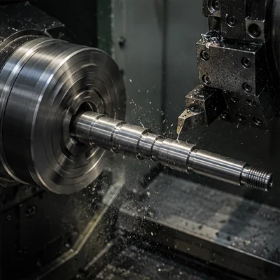
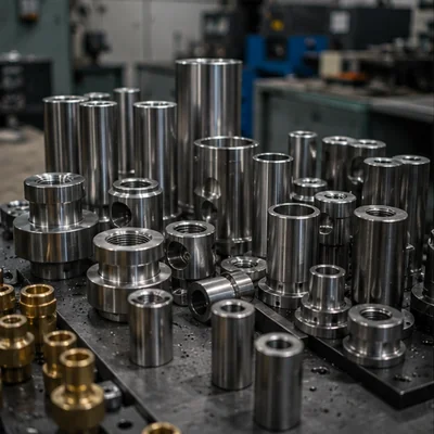
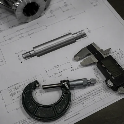
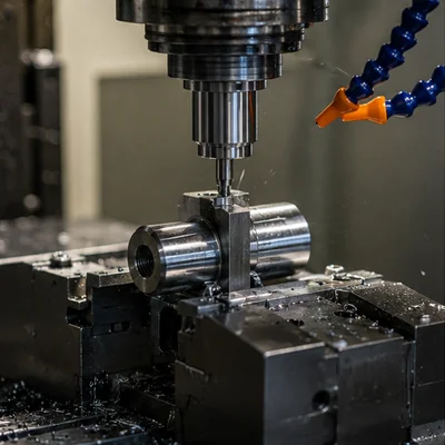
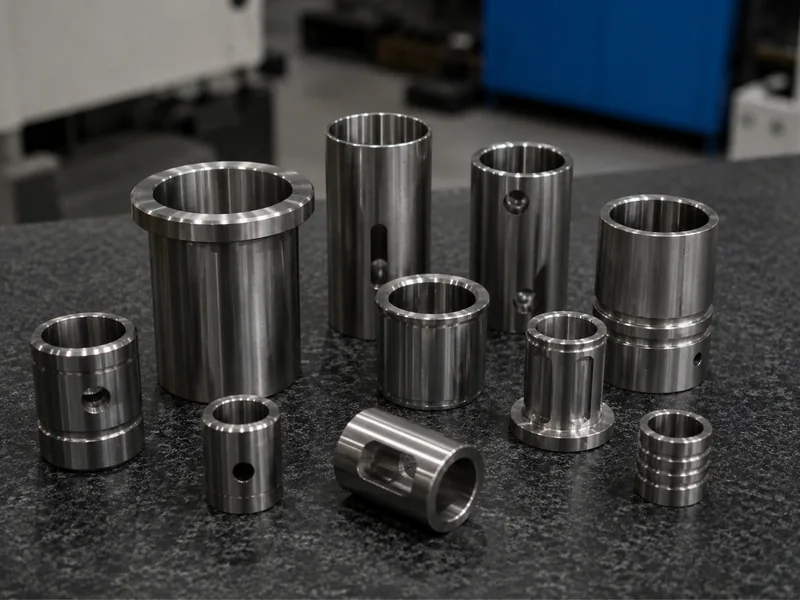
What Makes a Mechanical Sleeve “Custom”?
A custom mechanical sleeve is rarely just a piece of tube cut to length. While standard tubing serves structural purposes, precision mechanical assemblies require defined relationships between surfaces.
The drawing defines not only the size of the sleeve, but how it must guide, locate, protect or space other components.
Geometry Control
- • Precision ID & OD
- • Shoulders & Multiple diameters
- • Flanges & Stops
Functional Features
- • Internal/External Threads
- • Lubrication Grooves
- • Cross Holes & Chamfers
Custom Sleeve Types We Manufacture to Drawing Requirements
Categorized by mechanical function and structural geometry.
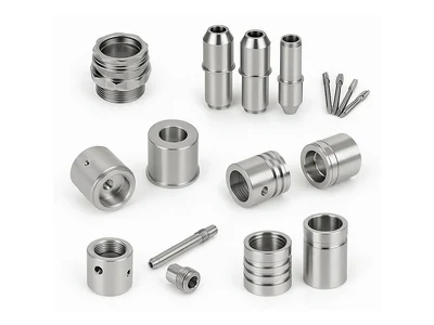
Custom Guide Sleeves
Designed to center shafts or pins, maintain alignment, and reduce unwanted lateral movement in assemblies.
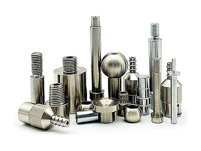
Custom Shaft & Wear Sleeves
Replaceable sleeves used to protect expensive shaft surfaces from wear, corrosion, or repeated seal contact.
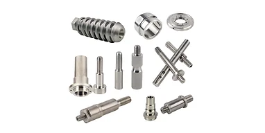
Custom Spacer & Distance Sleeves
Used to maintain a strictly defined axial distance between bearings, gears, or structural components.
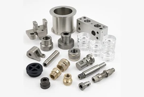
Custom Stepped & Shoulder Sleeves
Features multiple outer or inner diameters to provide transition zones or hard stops for mating parts.
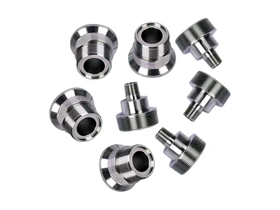
Custom Flanged Sleeves
Provides axial locating, a mounting reference, or increased contact area against a housing.
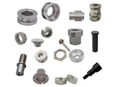
Custom Threaded Sleeves
Used for mechanical spacing, adjustment, connecting, or locating via internal or external threads.
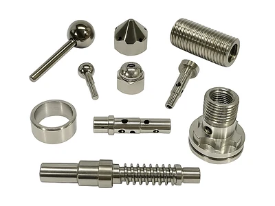
Custom Grooved Sleeves
Features oil grooves, retaining ring grooves, or cross-holes to support specific assembly requirements.
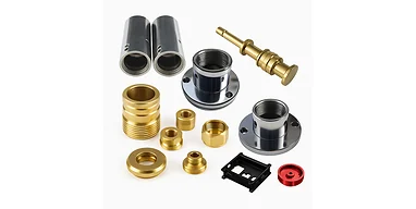
Thin-Wall Precision Sleeves
Lightweight or space-constrained sleeves requiring specialized machining to prevent clamping distortion.
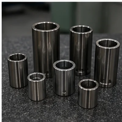
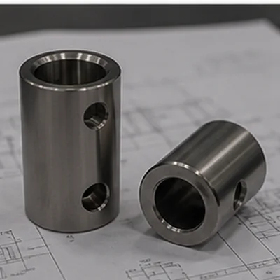
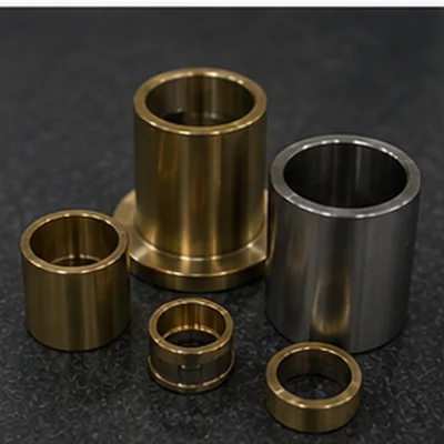
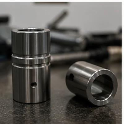
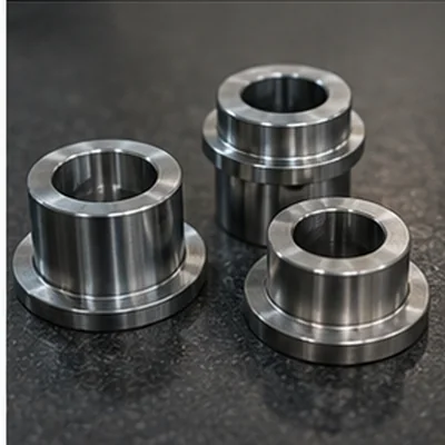
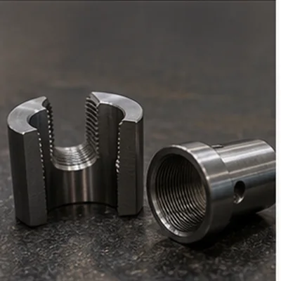
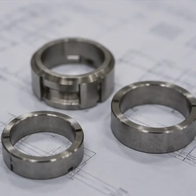
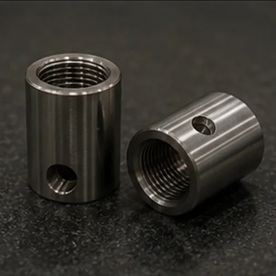
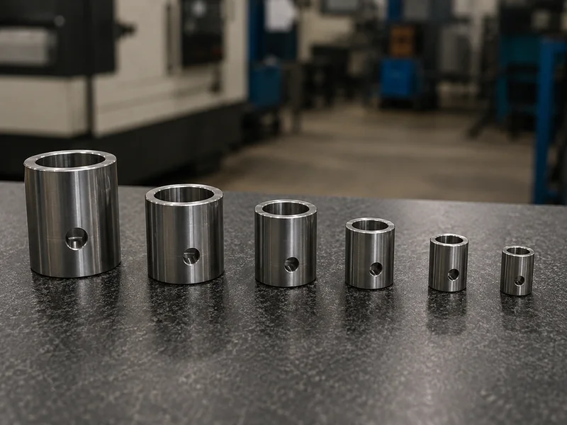
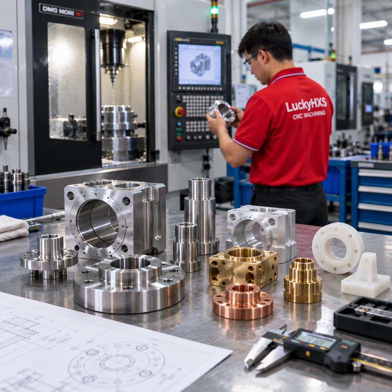
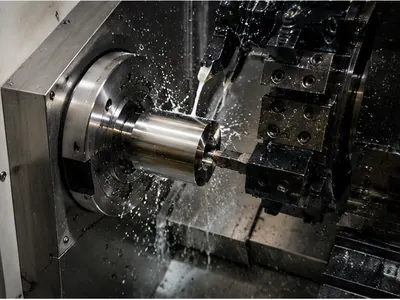
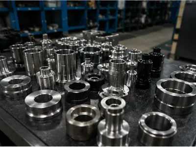
CNC Machined Sleeve Structures for Custom Assemblies
Visual proof of our turning and milling capabilities across different geometries and materials.
What Function Does Your Sleeve Need to Perform?
Select the sleeve around its assembly function first, then define geometry and material.
Guide
Ensure shaft, pin, or rod alignment during movement.
Protect
Provide a replaceable wear surface over an expensive shaft.
Space
Maintain exact axial distance between bearings or gears.
Locate
Provide a mechanical reference or hard stop surface.
Adapt
Connect different diameters, threads, or interfaces.
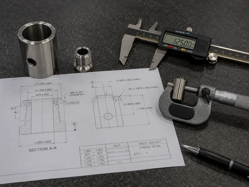
What Should You Specify on a Custom Sleeve Drawing?
To ensure the sleeve functions correctly in your assembly, your 2D/3D drawing should clearly define the critical interfaces.
Why Simple-Looking Sleeves Create Expensive Assembly Problems
A cylindrical part seems easy to machine, but functional failures often stem from these 10 overlooked details.
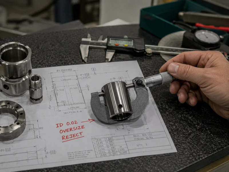
ID / OD & Fit Don’t Match the Assembly
A small diameter error can become a complete assembly failure.
The Challenge
Sleeves interface with shafts, pins, housing bores, seals, or bearings. If the ID is too small, the shaft won't enter. If too large, excessive play causes vibration. If the OD is too large, it won't install; too small, and it may rotate unwantedly.
Why It Happens
ID and OD are often reviewed separately without considering the mating dimensions. Press-fit deformation, housing variation, and tooling wear are frequently ignored during initial machining.
LuckyHxs Approach
We review ID and OD together, identify mating shaft/housing dimensions, confirm the intended fit, and perform first-article verification before batch runs.
Bore-to-OD Concentricity Drifts
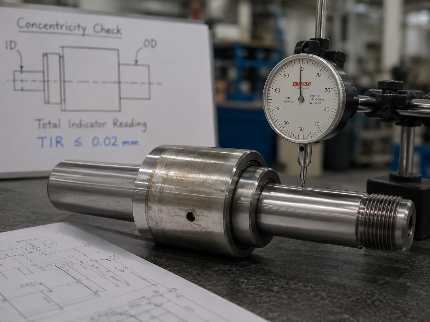
Are the bore and outer diameter actually on the same functional axis?
The Challenge
An ID and OD can individually pass inspection, but if they are not concentric, the assembly suffers from shaft runout, uneven clearance, vibration, uneven wear, or seal misalignment.
Why It Happens
Repeated clamping, poor datum transfer between separate ID/OD operations, tool deflection, and unstable workholding cause the center axis to shift during machining.
LuckyHxs Approach
We plan related cylindrical features around a controlled datum, reduce unnecessary re-clamping, and select CNC turning or turn-mill routes specifically to maintain concentricity callouts.
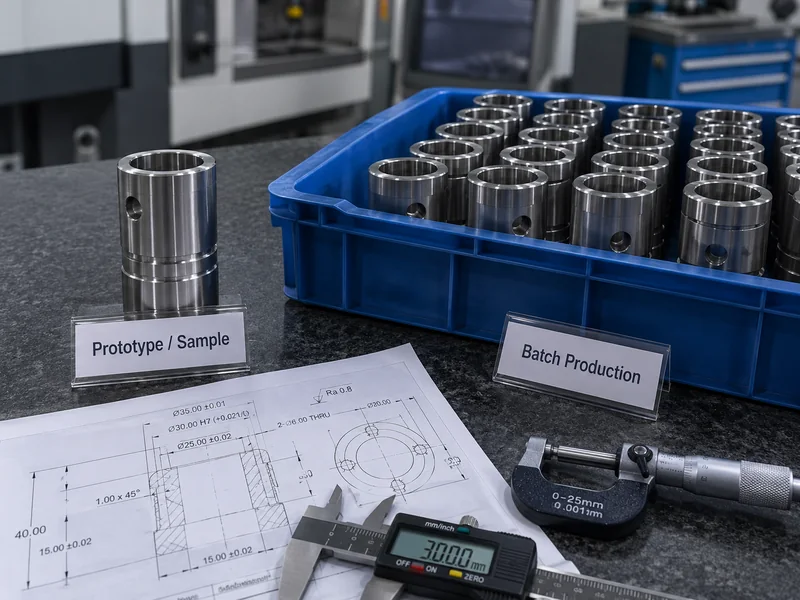
Sample-to-Batch Fit Changes
Prototype Fits → Production Batch Drifts
The Challenge
The prototype sleeve fits perfectly with clean edges and correct dimensions. But during the production batch, the ID drifts, groove positions change, or deburring varies, causing assembly line halts.
Why It Happens
Tool wear, setup changes, raw material variation, and lack of standard operating procedures between the prototype phase and mass production.
LuckyHxs Approach
We implement drawing revision control, identify critical dimensions from the first article, monitor tool wear, and retain repeat-order requirements to ensure batch-to-batch consistency.
Thin-Wall Sleeves Need Different Workholding Logic
A thin-wall part should be inspected in the condition that represents its real functional state. Thin-wall sleeves cannot be evaluated only while the part is still under clamping force.
- Clamping Pressure: Excessive chuck pressure causes ID distortion and OD ovality.
- Material Springback: Dimensions shift immediately after the part is released from the machine.
- Measurement Protocol: We mandate post-machining measurement (machining → unclamp → stabilize → inspect) to verify true roundness and concentricity.
Small Features Can Control the Entire Sleeve Function
A small groove may occupy only a fraction of the sleeve, but the wrong position can make the entire component unusable.
Grooves (Oil / Circlip / Relief)
Controls lubrication flow or retains mating rings.
Must Control: Width, depth, position, burr-free edges.
Threads (Internal / External)
Provides mechanical spacing, adjustment, or connection.
Must Control: Pitch, length, thread-to-bore relationship.
Shoulders & Flanges
Acts as an axial stop or mounting reference.
Must Control: Face squareness, precise axial position.
Choose Sleeve Material Around Function and Environment
Material selection dictates wear resistance, friction, weight, and compatibility with the mating shaft.
Stainless Steel
303 / 304 / 316 / 316L
Excellent for corrosion resistance and durable wear surfaces in harsh environments.
Aluminum
6061 / 6063 / 7075
Ideal for lightweight spacer sleeves and guides where heavy wear is not a factor.
Brass & Copper
H57 / H59 / H62 / C3604
Used for low-friction requirements, electrical conductivity, or specific aesthetic assemblies.
Free-Machining Steel
1214 / 1215
Cost-effective for high-volume structural spacers and distance sleeves.
Selected Engineering Plastics
POM (Delrin) and other confirmed materials
Used when non-marring contact, electrical insulation, or extreme light weight is required.
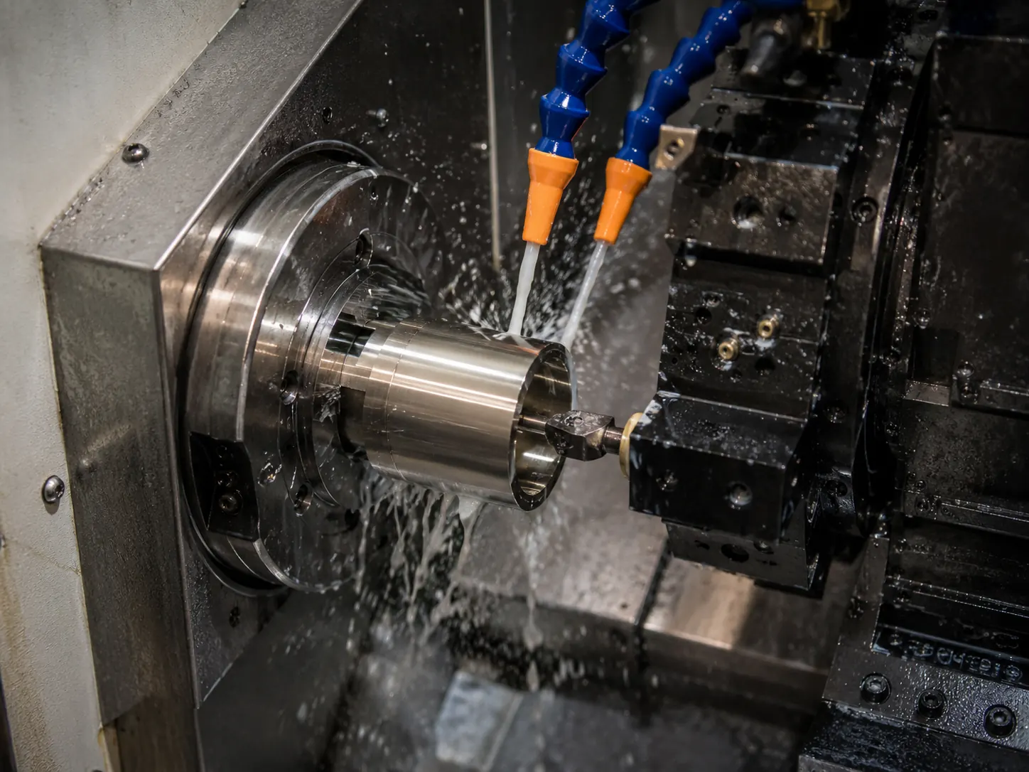
Machining Processes for Custom Precision Sleeves
The machining route is determined by the sleeve's diameter, length, wall thickness, geometry (holes/grooves/threads), quantity, and inspection requirements.
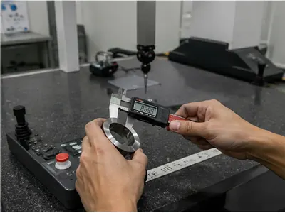
Inspect the Features That Control Real Sleeve Function
We don't just measure dimensions; we verify the functional fit for your assembly.
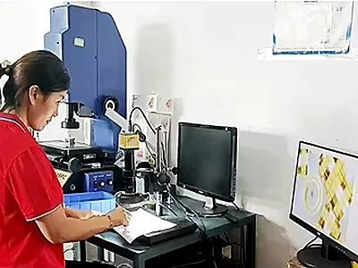
- 1 Drawing & Fit Review
- 2 Material Confirmation
- 3 First Article Verification
- 4 In-Process ID / OD Checks
- 5 Concentricity & Runout Review (where specified)
- 6 Groove & Thread Inspection
- 7 Bore, Edge & Burr Review
- 8 Final Inspection & Batch ID
Where Custom Mechanical Sleeves Are Used
Precision sleeves are critical components across major industrial sectors.

Industrial Automation
Guide Sleeves / Spacers
Aligning pneumatic cylinders and linear motion shafts.

Robotics
Thin-Wall / Flanged Sleeves
Compact joint spacing and lightweight shaft protection.
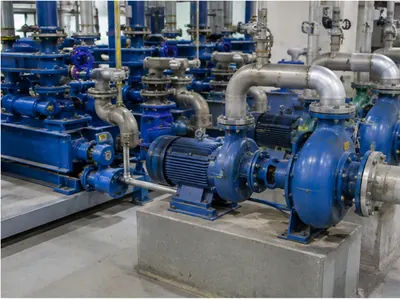
Pumps & Rotating Eq.
Shaft Wear Sleeves
Protecting main drive shafts from mechanical seal wear.
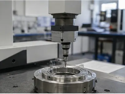
Precision Instruments
Stepped / Threaded Sleeves
Locating optical or sensor components with high concentricity.
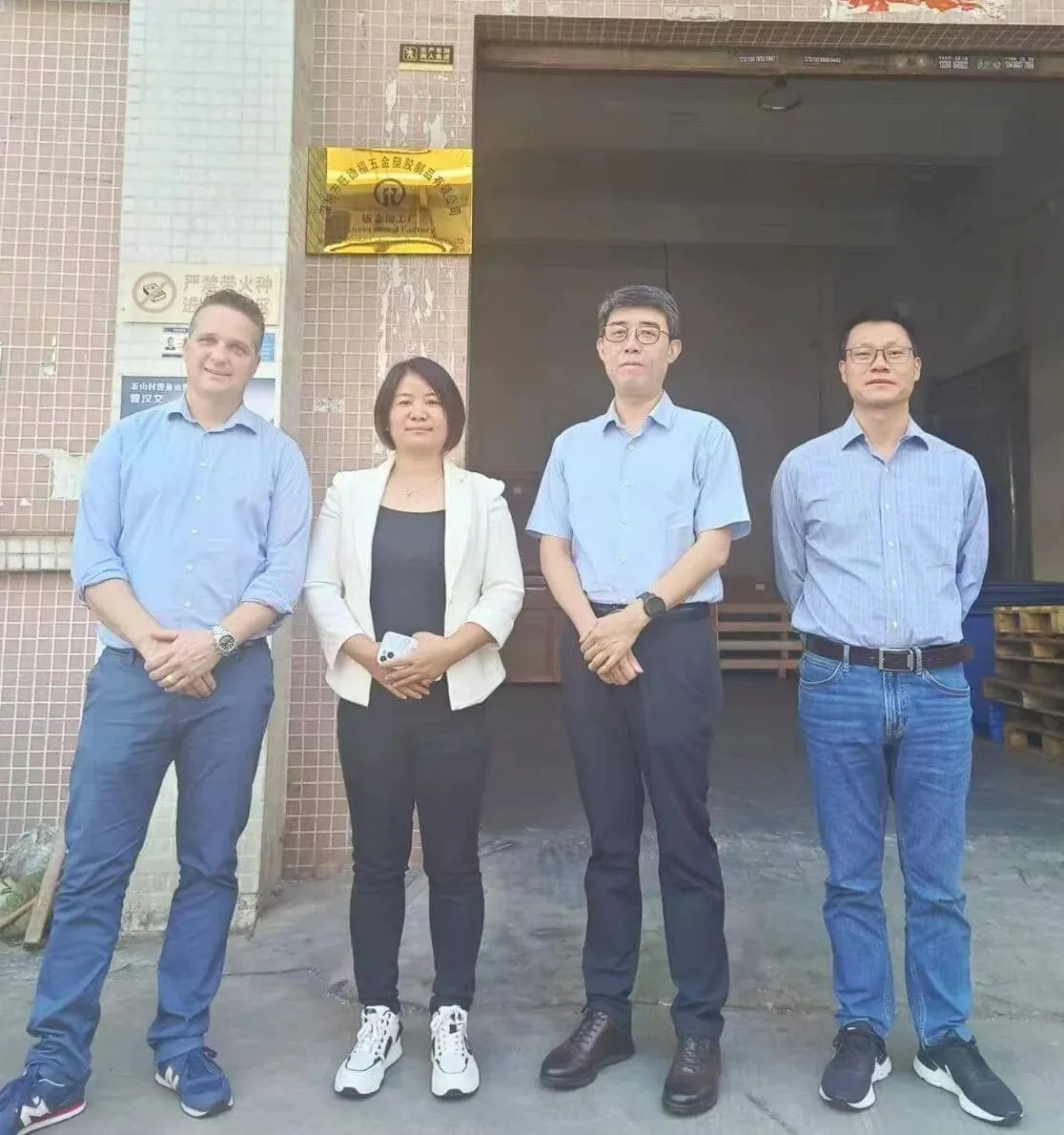
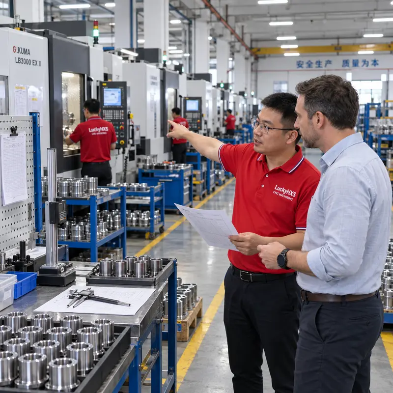
A CNC Manufacturing Partner You Can Verify
Certified production management and transparent factory operations.
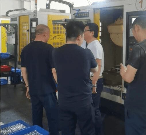
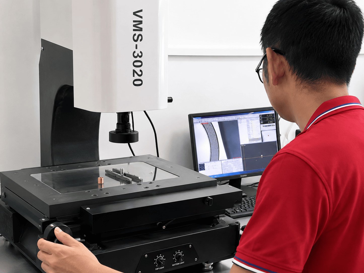
See How LuckyHxs CNC Parts Are Machined and Inspected
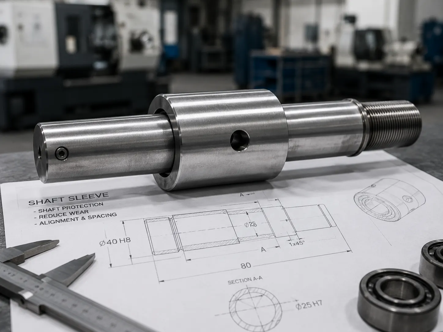
What Is a Shaft Sleeve and What Does It Do?
A shaft sleeve is a cylindrical component fitted over or around a shaft in order to protect, locate, guide or provide a replaceable functional surface, depending on the assembly design.
Shaft Protection & Replaceable Surface
The sleeve takes on wear, seal contact, and potential surface damage rather than exposing the expensive main shaft. Replacing a sleeve is more economical than replacing the entire shaft assembly.
Alignment, Location & Spacing
Precision sleeves center components and maintain strictly defined distances between gears or bearings.
What Should Buyers Specify?
Shaft diameter, sleeve ID/OD, length, intended fit, surface finish, material, runout/concentricity, and any functional grooves.
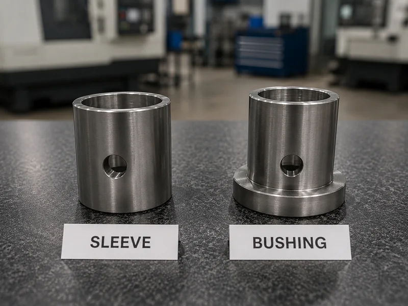
Sleeve vs. Bushing: What’s the Difference?
The terms can overlap, but buyers often use them differently depending on function.
Custom Sleeve
Primary Focus: Guide, protect, space, locate, adapt, or provide a replaceable surface over a shaft.
Examples: Shaft Sleeve, Guide Sleeve, Spacer Sleeve, Threaded Sleeve.
Bushing
Primary Focus: Shaft support, bearing surface, sliding contact, friction/wear control.
Examples: Sleeve Bushing, Flanged Bushing, Plain Bearing Bushing.
Why Does the Difference Matter for RFQ? Suppliers need to know if the part primarily handles motion, wear, locating, or spacing. Describe the function, not only the part name.
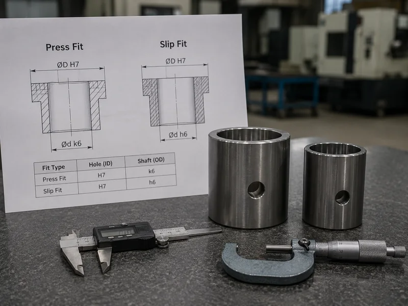
Press Fit vs. Slip Fit Sleeves: How Should ID/OD Be Specified?
Press Fit
Used for controlled retention, positioning, and secure housing relationships. The final fit depends heavily on material, wall thickness, and installation method. Installation force can alter the ID and roundness of thin-wall sleeves.
Slip Fit
Allows for easier installation, removal, and servicing of replaceable components. However, excessive clearance leads to vibration and misalignment.
Specify the Assembly, Not Just the Sleeve
Free-State Dimension ≠ Installed Functional Dimension. Always provide sleeve ID/OD, shaft diameter, housing bore, intended fit, and wall thickness.
Frequently Asked Questions About Custom CNC Sleeves
What is a custom machined sleeve?
What is the difference between a sleeve and a bushing?
What types of sleeves can you machine?
How do you control sleeve ID / OD and concentricity?
Can you machine thin-wall sleeves?
Can you machine threads, grooves and cross holes in sleeves?
What materials can be used for custom sleeves?
What information do you need for a custom sleeve quotation?
Need a Custom Sleeve That Fits the Real Assembly?
Send your 2D/3D drawing, ID, OD, length, shaft size, housing dimensions, fit requirement, material, wall thickness, thread or groove details, quantity and inspection requirements. Our team will review the critical sleeve features and machining route before quotation.
Email: admin1@lucky-hxs.com
Phone: +86 13342931453
Address: Shenzhen Bao'an Songgang