
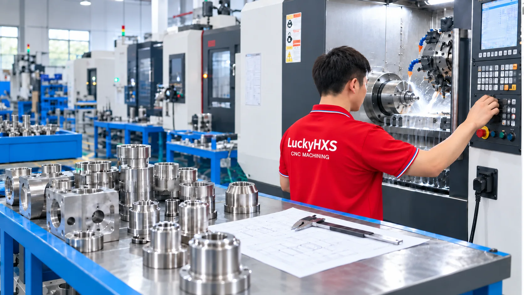
Prototype CNC Machining Services from a Custom Parts Manufacturer
LuckyHXS machines custom prototype parts from your 2D drawings, 3D CAD files or approved samples. We review geometry, material, critical features and the purpose of the prototype before selecting CNC milling, turning, Swiss machining or a turn-mill route.
- CNC milling, turning, Swiss and turn-mill prototype routes
- Aluminum, stainless steel, brass, copper, steel, POM and PTFE options
- DFM review, critical-feature planning and prototype-to-batch continuity
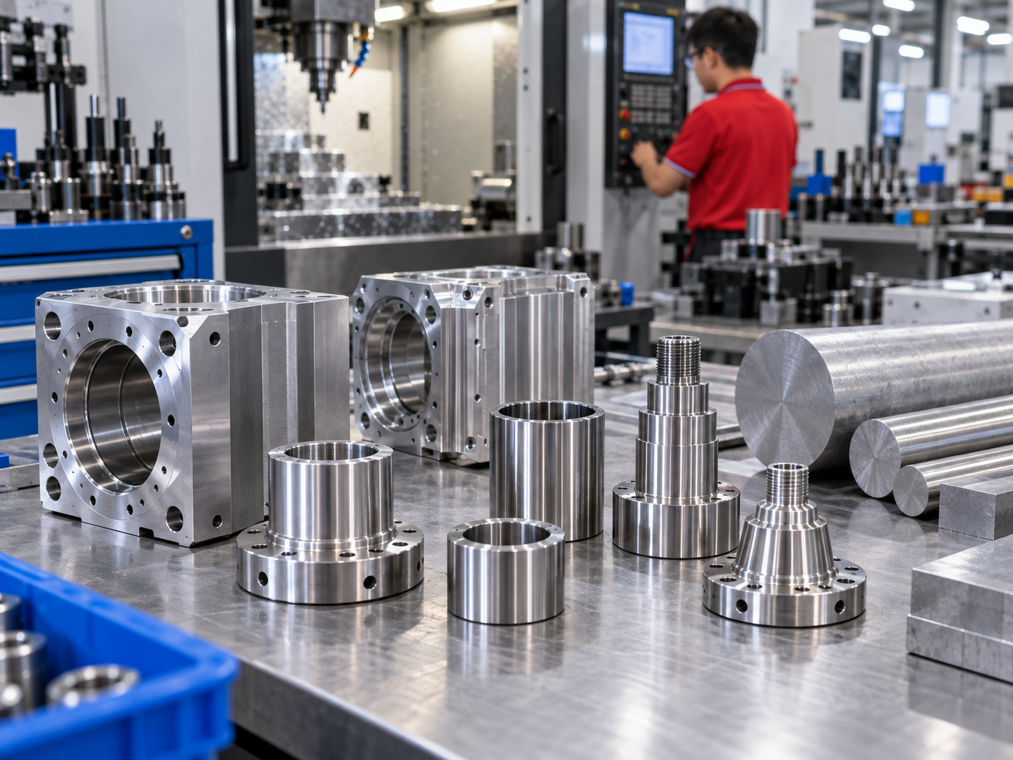
Prototype CNC Machining for Parts That Need More Than a Visual Model
Prototype CNC machining removes material from solid metal or engineering-plastic stock to produce a part from controlled CAD geometry and drawing requirements. It is especially useful when a development team needs to evaluate machined interfaces, holes, threads, fits, datums, surface conditions or material behavior before committing to repeat production.
LuckyHXS supplies made-to-drawing prototype components rather than complete finished products. The machining scope, inspection points and surface requirements are agreed for each project. Final assembly testing, end-use validation and product approval remain the customer’s responsibility.
- Machined from solid stock
- Feature-specific drawing review
- Project scope confirmed before production
Choose a Prototype Machining Route Around the Part Geometry
The right prototype route depends on the part’s dominant geometry, feature relationships, material and expected next production stage. These four routes cover the main drawing-based prototype work supported by LuckyHXS.
CNC Milled Prototypes
For housings, brackets, plates, blocks and parts with pockets, mounting faces or features on several sides. Milling is usually the starting point when the component is mainly prismatic rather than rotational.
CNC Turned Prototypes
For shafts, pins, sleeves, bushings, fittings and threaded components built around a rotational axis. Turning is suited to prototypes where diameters, shoulders, bores, grooves or threads define the part.
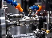
Swiss-Machined Prototypes
For small-diameter, slender and feature-dense parts such as miniature shafts, pins, connectors and threaded components. Process fit depends on diameter, length-to-diameter ratio and the relationship between small features.
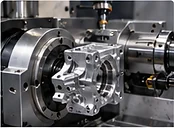
Turn-Mill Prototype Parts
For rotational components that also contain flats, slots, cross holes, radial ports or other off-axis features. A suitable turn-mill route can reduce unnecessary re-clamping while keeping related features referenced to the correct datum.
Prototype Parts Machined from Your Drawings
Prototype projects are not limited to one standard component shape. LuckyHXS reviews each part according to its geometry, functional interfaces and machining requirements.
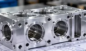
Housings and Enclosures
Machined bodies with pockets, mounting faces, openings, threaded holes and assembly interfaces.
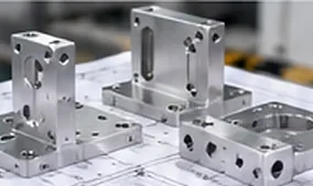
Brackets and Mounting Plates
Structural parts used to locate, support or connect components during product development.
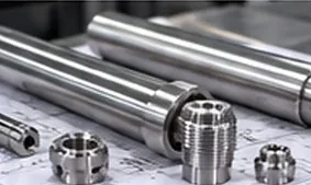
Shafts and Pins
Rotational or locating components with diameters, shoulders, grooves, threads and fit requirements.
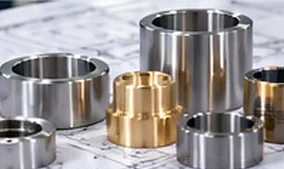
Bushings and Sleeves
Cylindrical components where bore size, wall thickness, concentricity or assembly clearance may affect function.
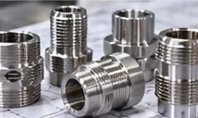
Connectors and Fittings
Custom connection components with threads, bores, sealing features, ports or conductive surfaces.
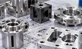
Custom Mechanical Components
Non-standard prototype parts that combine multiple surfaces, holes, interfaces or assembly features in one drawing.
Define What the Prototype Must Prove
A prototype should answer a specific engineering question. Defining that question before machining helps align the material, tolerances, inspection points and production route.

Boundary note: LuckyHXS supplies machined prototype components. Product-level testing, regulatory assessment and final performance validation remain with the customer.
Form and Geometry
Confirm overall shape, envelope, clearances and visible geometry before the design advances.
Fit and Assembly
Review mating features, locating surfaces, hole positions, threads and interfaces with surrounding components.
Material-Based Function
Use the specified stock material when the prototype must reflect relevant stiffness, weight, conductivity, wear or machining characteristics.
First-Article Readiness
Identify critical dimensions, datums and inspection requirements that may need to remain controlled after prototype approval.
Pilot-Batch Preparation
Evaluate whether the prototype route, fixture concept and inspection plan are suitable for a small follow-on batch.
Compare CNC Routes for Your Prototype
Start with the dominant geometry, then review critical features, setup count, material and the expected quantity after approval.
| Machining Route | Best-Fit Geometry | Typical Prototype Parts | Main Review Points |
|---|---|---|---|
| CNC Milling | Prismatic, pocketed or multi-face parts | Housings, brackets, plates, blocks | Datums, internal corners, pocket depth, hole position and setup access |
| CNC Turning | Mainly rotational geometry | Shafts, pins, sleeves, bushings, fittings | OD/ID relationships, shoulders, grooves, threads and runout requirements |
| Swiss Machining | Small, slender and bar-fed geometry | Small shafts, pins, connectors, threaded parts | Length-to-diameter ratio, small features, cutoff condition and feature relationships |
| Turn-Mill Machining | Rotational parts with off-axis features | Ported sleeves, cross-hole shafts, fittings and complex connectors | Rotational datum, angular position, cross holes, flats, slots and secondary setups |
Materials for CNC Machined Prototypes
Material choice should follow the question the prototype needs to answer. Exact grade availability, stock condition and project suitability are confirmed during drawing review.
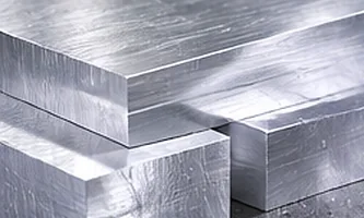
Aluminum Alloys
Available project examples include 6061, 6063, 7075, 2024 and 5052. Aluminum is commonly considered when weight, machinability, thermal behavior or anodized appearance matters.
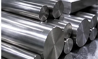
Stainless Steel
Available project examples include 303, 304 and 316F. Review corrosion needs, strength, surface condition, cutting behavior and any application-specific material requirements.
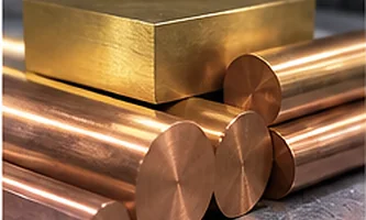
Brass and Copper
Available project examples include H57/C3602, H59/C3604, H62 and copper. These materials may be selected for machinability, conductivity, appearance or connection components.
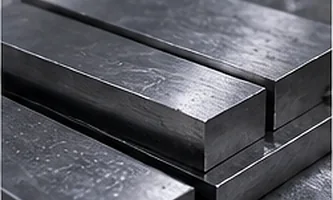
Free-Machining Steel
Available project examples include 1214 and 1215. Confirm strength, magnetic requirements, corrosion protection and the planned surface treatment.
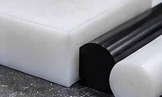
POM
POM may be suitable for prototype bushings, guides, spacers and mechanical components
where low friction and machinability are useful.
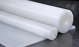
PTFE
PTFE may be considered for low-friction, insulating or chemically resistant component concepts, subject to dimensional and deformation requirements.
Closing note: Do not substitute a similar material without approval when the prototype is intended to validate material-dependent behavior.
Plan Surface Condition Before the Prototype Is Machined
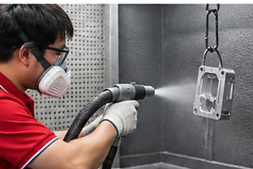
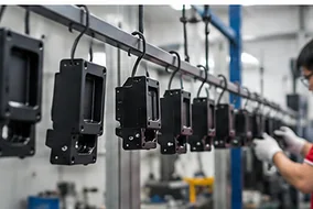
Surface treatment can change dimensions, edge condition, appearance and the way a prototype fits with surrounding parts. Define cosmetic surfaces, functional surfaces, masking areas and dimensions that require inspection after finishing.
As-Machined and Deburred
Use when machining marks are acceptable and the main requirement is a clean, usable component with controlled edges.
Anodizing or Sandblasting for Aluminum
Confirm alloy, color expectation, visible surfaces, masking and any dimensions affected by the finish.
Black Oxide, Nickel or Zinc Plating for Steel
Confirm the coating requirement, corrosion expectation and whether critical dimensions need post-finish verification.
Finish According to Drawing
For brass, copper, stainless steel and engineering plastics, define appearance, roughness, edge condition and any functional surface directly on the drawing.
Callout: A prototype that passes before finishing may not pass after finishing if coating allowance and inspection timing are not defined.
Review Manufacturability Before Material Is Cut
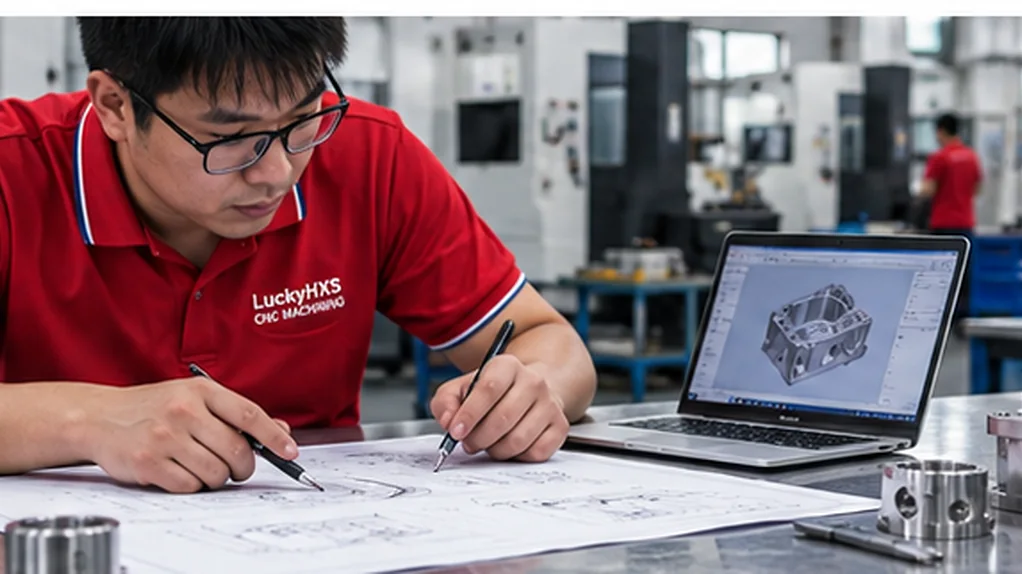
Prototype DFM should protect the intended function while identifying features that affect machining access, setup, tooling, inspection or finishing. Any proposed design change remains subject to customer approval.
- Machining access and required setups
- Functional datums and critical relationships
- Wall thickness, pocket depth and tool reach
- Internal corner radii and cutter access
- Hole, thread and edge definitions
- Surface-treatment allowance and inspection timing
- Prototype quantity and expected follow-on quantity
- Features requiring a specific inspection method
The goal is not to simplify every design. It is to separate features that must remain unchanged from features that may have a more practical manufacturing option.
Geometry Details That Can Change the Prototype Plan
Thin Walls
Thin sections may move during machining or inspection. Review wall thickness together with material, unsupported length and clamping direction.
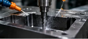
Deep Pockets
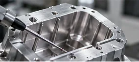
Deep cavities can require long tools, additional setups or different corner radii. Tool access should be reviewed before quoting.
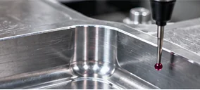
Sharp Internal Corners
Rotating cutters naturally create an internal radius. Specify where a sharp condition is functional and where a practical radius is acceptable.
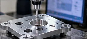
Small or Deep Holes
Hole diameter, depth, entry angle, exit condition and burr access can affect the machining and inspection route.
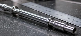
Long Slender Features
Small shafts, pins and unsupported features may require a Swiss or alternative turning approach to control deflection.
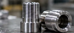
Threads and Edge Breaks
Define thread standard, class, depth, runout area, entrance chamfer and burr requirements where assembly depends on them.
Inspect the Relationship, Not Only the Dimension
A prototype can contain individually acceptable dimensions and still fail assembly if the functional relationships are not defined. Connect each critical feature to the datum or mating condition that gives it meaning.
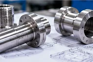
Shafts and Rotational Parts
Review diameter, bore, shoulder, runout and concentricity according to the surfaces that locate or rotate in the assembly.

Housings and Brackets
Review mounting datums, hole position, flatness and face relationships that control alignment with other components.
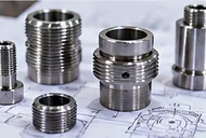
Threaded Components
Review thread form, position, engagement length, entry chamfer and the surface from which thread depth is measured.
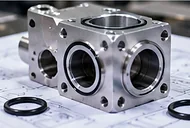
Ported and Sealing Components
Review port position, sealing face, groove geometry, cross-hole intersections and internal burr access.
Critical features should be identified on the controlled drawing so the machining and inspection plan evaluates the same functional requirement.
CNC Machining or 3D Printing for a Prototype?
Choose the process around the question the prototype must answer.
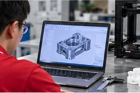
Consider 3D Printing When
- The main goal is an early form or visual study
- Complex internal geometry is more important than machined surfaces
- The part does not need to represent stock-material behavior
- Very fast design iteration matters more than final surface condition
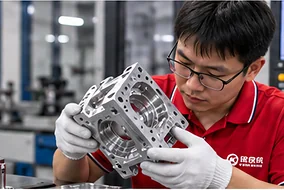
Consider CNC Machining When
- The prototype needs the specified metal or engineering plastic
- Threads, bores, sealing faces or machined fits must be evaluated
- Datums and feature relationships affect assembly
- The design may continue into first-article or pilot-batch machining
Some development programs use both methods: an additive model for early geometry review and a CNC machined version for material, interface or assembly evaluation. The appropriate route depends on what must be validated.
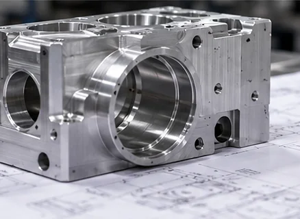
Use Tight Tolerances Where Function Requires Them
Applying the tightest tolerance to every dimension can add setup, machining and inspection work without improving the prototype. A clearer drawing separates functional requirements from general geometry.
Define General Dimensions
Use practical general tolerances for features that do not control fit, alignment, sealing or motion.
Mark Critical-to-Function Features
Identify the dimensions and relationships that decide whether the prototype performs its intended role.
Establish the Datum Scheme
Show how the part is located during assembly and how critical features should be measured.
Match the Inspection Method
Confirm whether a feature is checked with micrometers, gauges, optical equipment or another agreed method.
Confirm Acceptance Conditions
State whether dimensions are evaluated before or after surface treatment and identify any mating-part conditions.
Keep the CAD Model, Drawing and Prototype Revision Aligned
Prototype changes often happen quickly. Machining should begin from one confirmed requirement set rather than a mixture of different file revisions, emails and informal notes.
The 3D model communicates geometry. The 2D drawing communicates tolerances, datums, threads, finish notes and inspection requirements. If the files differ, identify which document governs before production begins.
Repeat-order note: Reconfirm the latest revision before a prototype, pilot batch or repeat order is released.
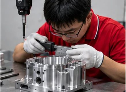
Plan Inspection Around the Prototype Decision
The inspection plan should focus on the features that determine whether the prototype can move to assembly, testing or the next production stage.
Level 1: Visual and Basic Dimensional Review
Check part identity, obvious damage, edge condition and agreed general dimensions.
Level 2: Critical Feature Inspection
Measure the diameters, holes, datums, positions, threads or interfaces identified as critical on the drawing.
Level 3: Assembly-Related Checks
Review mating dimensions, fit conditions and functional relationships that can be evaluated from the agreed component requirements.
Level 4: Requested Records
Confirm any dimensional report, material document, inspection record or special format during quotation rather than assuming it is included.
Build the Prototype with the Next Batch in Mind
A prototype should validate the part, but it can also establish information needed for a controlled follow-on order.

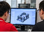
Stage 1: Prototype
Machine the first parts from the confirmed revision and review the specified features.
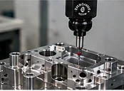
Stage 2: Design Feedback
Record approved changes to geometry, tolerance, material, finish or inspection requirements.
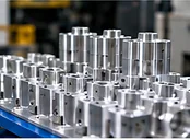
Stage 3: First Article
Confirm the revised requirement set and the features that must remain controlled.
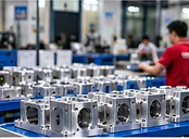
Stage 4: Pilot Batch
Review fixture, tooling, inspection and handling needs under a small repeated quantity.
Stage 5: Repeat Production
Reconfirm the approved revision, material, critical features and inspection scope before each production release.
Closing copy: Prototype approval does not automatically prove repeat-production consistency. The production route and controls should be reviewed before quantity increases.
Reduce Avoidable Risk Before Prototype Approval
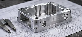
The Part Looks Correct but Does Not Assemble
A prototype may match its general shape while mating holes, locating surfaces, fits or threads remain misaligned.
Define the assembly datums, mating conditions and critical feature relationships on the controlled drawing.
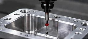
Every Dimension Is Marked as Critical
Blanket tight tolerances can increase machining and inspection work while hiding the few dimensions that actually determine function.
Separate functional dimensions from general geometry and assign inspection effort accordingly.
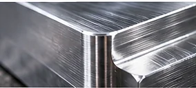
The Finish Changes the Fit
Coating, blasting or plating can affect edge condition, hole size, thread fit and mating surfaces.
Define masking, allowance and post-finish inspection requirements before machining begins.
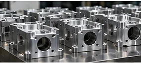
The Prototype Passes but the Next Batch Drifts
Changes to setup, tooling, revision or inspection can create differences between an approved sample and later parts.
Review the intended production route during the prototype stage and retain the approved requirement and inspection basis.

Why Use LuckyHXS for Prototype CNC Parts?
Four Machining Routes
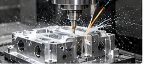
Milling, turning, Swiss and turn-mill options allow the process to follow the part geometry rather than forcing every design into one machine type.
Drawing- and Sample-Based Manufacturing
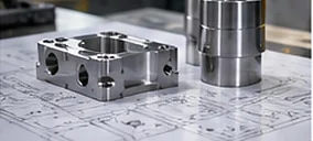
Prototype parts are reviewed against customer files, approved samples and agreed technical requirements.
Metal and Engineering-Plastic Options
Supported materials include aluminum, stainless steel, brass, copper, free-machining steel, POM and PTFE options for different prototype needs.
Manufacturability Review
Geometry, datums, critical features, surface requirements and inspection needs are reviewed before the machining route is confirmed.
Prototype-to-Batch Continuity
The approved revision and critical requirements can form the starting point for first-article, pilot-batch and repeat-order discussions.
Feature-Focused Inspection
Inspection planning can concentrate on the dimensions, threads, fits and relationships that affect the intended component function.
Prototype Components for Product Development
LuckyHXS machines components for development projects across different equipment and assembly environments. Final material, validation and compliance requirements remain project-specific.
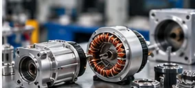
Motors and Motion Systems
Prototype shafts, sleeves, mounting parts and related components where fit, rotation and alignment require review.

Industrial Automation and Robotics
Brackets, housings, pins, bushings, fixtures and connection components for mechanical integration.
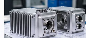
Electronics and Instrumentation
Enclosures, mounting plates, connectors and precision components with controlled interfaces and visible surfaces.
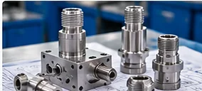
Fluid-Control Equipment
Fittings, valve-related components, ported parts and sleeves where threads, sealing faces and internal burr control may matter.
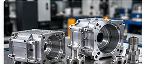
Automotive and EV Development
Prototype mounting, motion, connector and housing components made to project drawings for assembly evaluation.
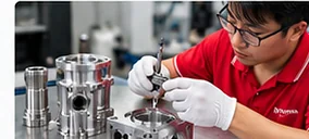
Medical Equipment Components
Custom housings, sleeves, shafts, fittings and instrument components for equipment development. Device-level validation, regulatory approval and final application responsibility remain with the customer.
Manufacturing and Inspection in Shenzhen
LuckyHXS is the precision machining brand of Shenzhen Hongxiangsheng Technology Co., Ltd. Prototype parts are manufactured from customer drawings through process planning, machining, in-process review, finishing coordination and final inspection according to the agreed project scope.
The factory supports CNC turning, CNC milling, Swiss machining, automatic-lathe machining and turn-mill production for custom metal and engineering-plastic components. The selected route depends on geometry, material, feature relationships, quantity and inspection requirements.
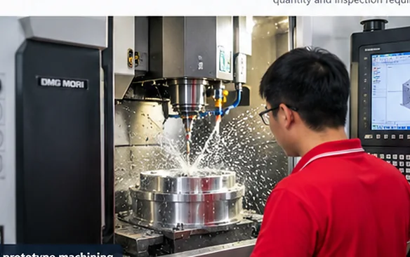
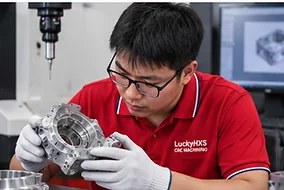
CNC prototype machining

Drawing and process review
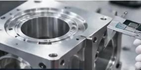
Dimensional inspection
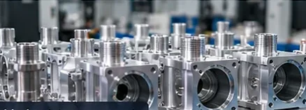
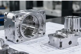
Finished prototype components
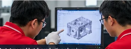
Prototype and batch production planning
Prototype CNC Machining Buyer Guide
Review these common questions to help align your design, timeline and expectations before starting a prototype machining project.
What is prototype CNC machining?
When should I choose CNC machining instead of 3D printing?
Consider CNC machining when the prototype must use a specified stock material, include machined threads or bores, evaluate sealing or mating surfaces, or maintain controlled relationships between features. Consider 3D printing when early shape review, complex internal geometry or rapid visual iteration is the main objective. Some projects use both methods at different development stages. The correct choice depends on what the prototype must prove.
Which CNC process fits my prototype?
What files should I provide for a prototype quote?
Provide the latest 3D CAD file where available and a controlled 2D drawing for tolerances, datums, threads, surface notes and inspection requirements. Also identify the material grade, prototype quantity, expected follow-on quantity, critical features, finish, revision and units. If the CAD model and drawing differ, state which document governs. Reference images or an approved physical sample may provide additional context but should not replace critical dimensions.
Can LuckyHXS machine a one-off prototype?
What determines prototype machining cost and schedule?
The main drivers include material and stock size, removed material, geometry, number of setups, tool access, feature depth, tolerances, threads, surface treatment, inspection scope and quantity. A simple-looking part may require complex workholding or several operations, while a more detailed part may fit an efficient machining route. Pricing and timing should therefore be confirmed from the actual files rather than estimated from a generic machine-hour rate.