
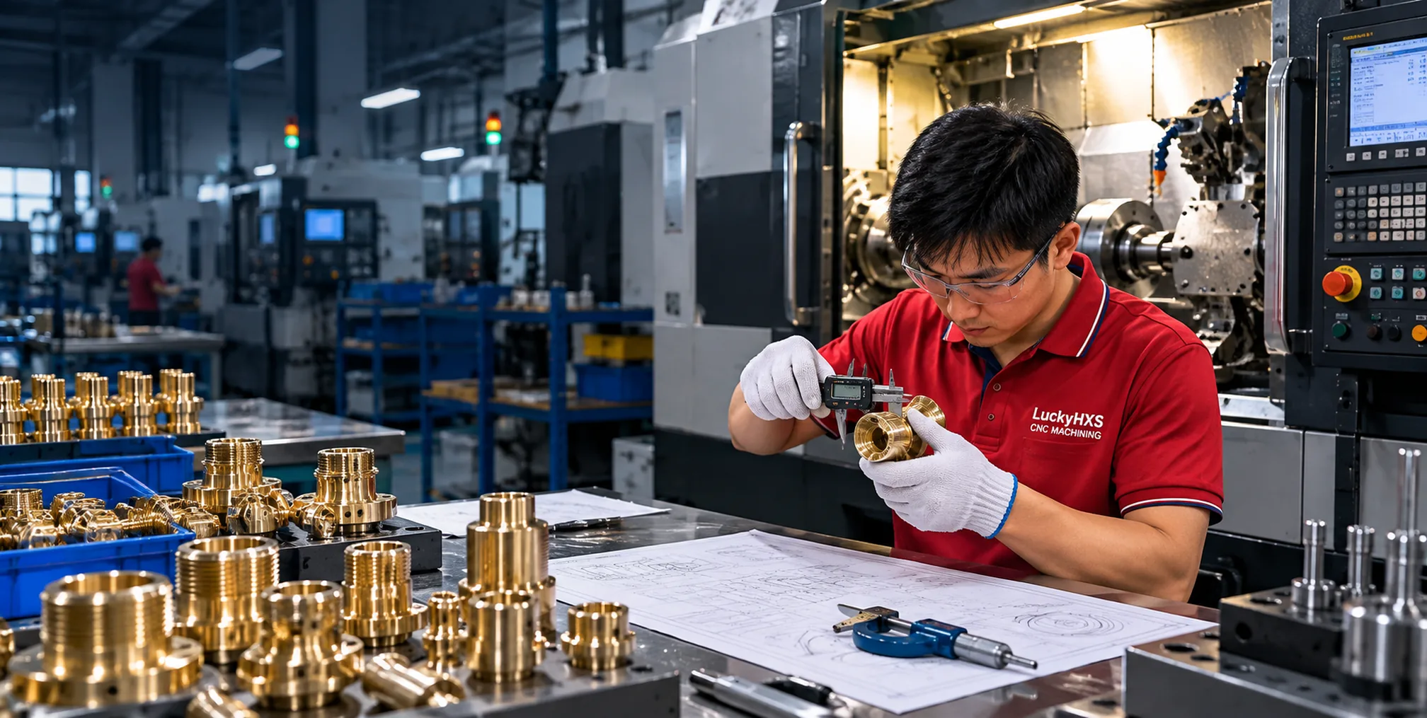
Custom Brass CNC Turned Parts Manufacturer for Drawing-Based Components
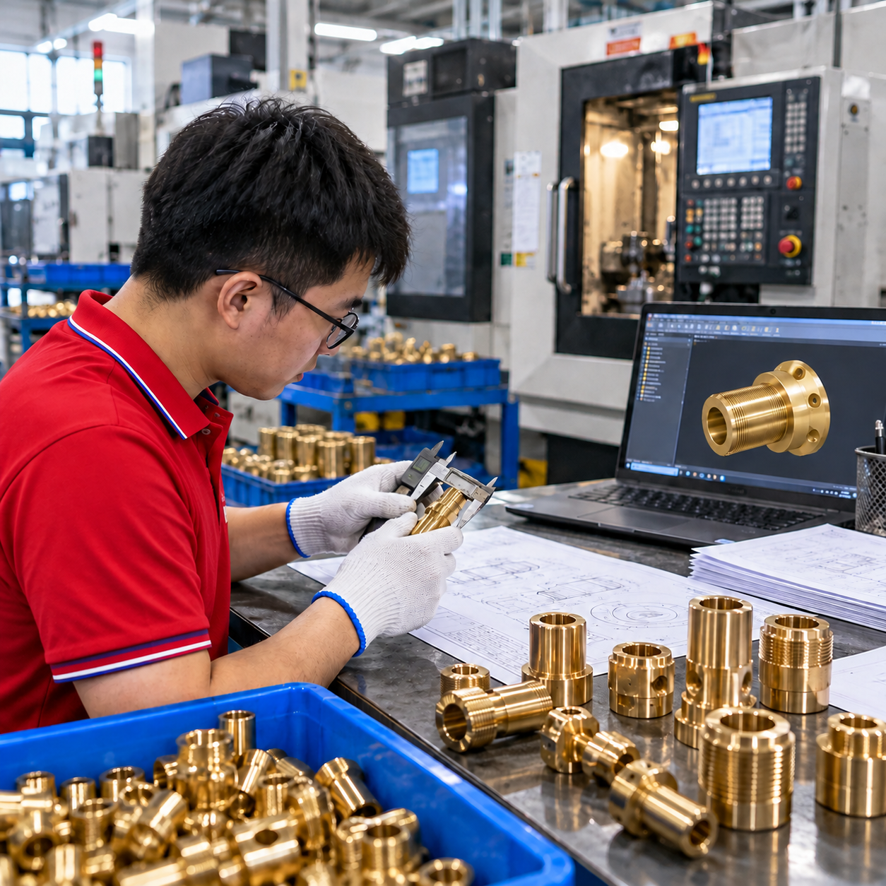
LuckyHXS manufactures custom brass CNC turned parts from customer drawings, samples and technical specifications. We review the brass grade, feature relationships, machining route and inspection requirements before production.
- Threaded inserts, knurled nuts, bushings, sleeves, pins and fittings
- CNC turning, Swiss-type turning, automatic-lathe turning and turn-mill processing
- Feature-focused review for threads, bores, outside diameters, concentricity and finish
Brass CNC Turned Parts Built Around Functional Features
Drawing-Based Production
Parts are reviewed against the supplied drawing revision, material grade, critical dimensions and intended assembly.
Multiple Machining Routes
CNC turning, Swiss-type turning, automatic-lathe turning, CNC milling and turn-mill processing are selected according to geometry.
Brass Grade Review
H57, C3602, H59, C3604, H62, H65 and other drawing-specified grades are reviewed according to project requirements.
Feature-Specific Inspection
Inspection can focus on thread fit, bore-to-OD relationships, concentricity, small holes, wall thickness, edges and surface condition.
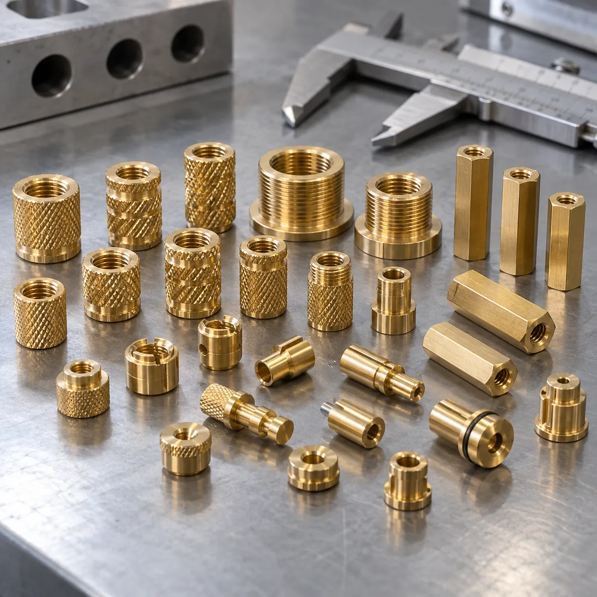
What Are Brass CNC Turned Parts?
Brass CNC turned parts are precision components produced by rotating brass bar stock while cutting tools create the required diameters, shoulders, bores, threads, grooves, chamfers and end features. The finished part may be simple and cylindrical or may combine turned features with drilling, milling, knurling or off-axis details.
Brass is often selected for machinability, electrical conductivity, corrosion resistance, threaded geometry and a clean machined appearance. The final result still depends on the exact alloy, component geometry, process route, surface finish and inspection condition.
The correct machining route begins with the functional relationship between the features, not only the part name.
Custom Brass CNC Turned Parts We Machine
Choose the part family closest to your drawing. LuckyHXS reviews the alloy, machining route, inspection points and finishing allowance around the component’s intended function.
Brass Threaded Inserts & Knurled Nuts
Internal threads, external knurls, flanges, blind holes and through-hole structures for molded or assembled components.
Brass Bushings, Sleeves & Spacers
Unthreaded bores, thin walls, flanged profiles and controlled ID-to-OD relationships for rotating or locating assemblies.
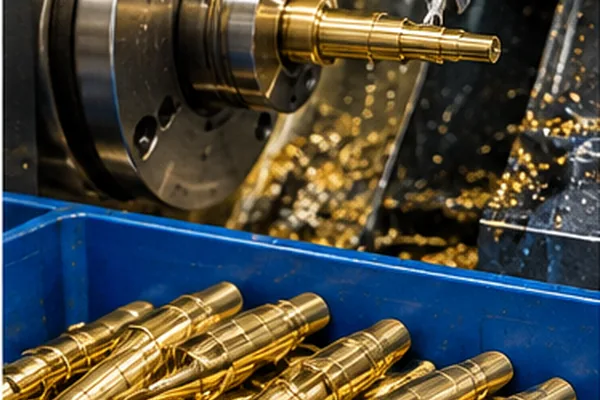
Brass Pins, Contacts & Turned Parts
Straight, stepped, grooved, threaded or cross-drilled parts where diameter, length, straightness and edge condition influence assembly.
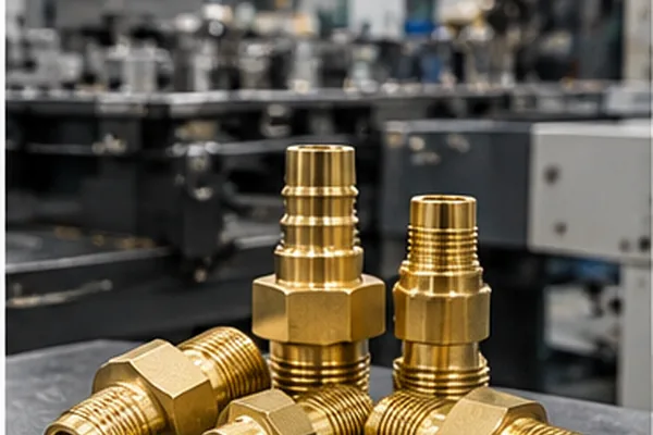
Brass Fittings, Adapters & Couplings
Compact parts with internal or external threads, connecting bores, mating faces and multiple diameters.
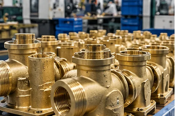
Brass Valve Bodies & Fluid Components
Drawing-defined ports, orifices, passages and sealing surfaces for fluid-control hardware.
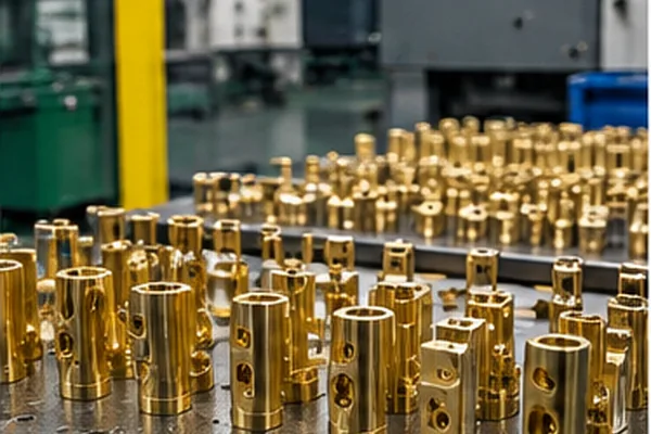
Brass Electrical Connectors & Terminals
Machined contact and connection structures where alloy identification, fit, surface condition and finishing requirements must be coordinated.
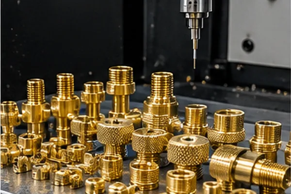
Brass Instrument & Micro Components
Small components with fine features, controlled fits, small holes or appearance-sensitive surfaces.
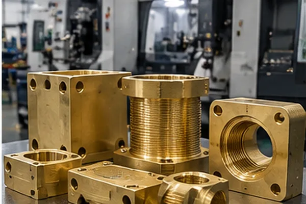
Custom Brass Housings & Mounting Parts
Milled or turn-milled structures with pockets, mounting holes, multiple faces and drawing-defined datums.
Select the Brass Grade Around Machining and Service Requirements
The alloy designation affects chip formation, tool behavior, cycle planning, surface appearance and the suitability of the finished part for its operating environment. Always state the full grade and material standard when the drawing or end use requires a specific composition.
| Grade or material direction | Machining consideration | When to review |
|---|---|---|
| H57 / C3602 | General brass options represented in the current material range. Confirm the exact standard, composition and functional requirement. | Use when the drawing already specifies the grade or the material must match an existing component. |
| H59 / C3604 | Often reviewed where machining efficiency and stable chip control are important. | Consider for turned inserts, bushings, pins, threaded parts and other geometry where machinability is central. |
| H62 / H65 | Softer brass options may require closer attention to tool condition, chip evacuation, surface marks and cycle planning. | Consider when formability, appearance or a drawing-defined material requirement takes priority. |
| Lead-Free or DZR Brass | These requirements are grade- and standard-specific and must not be inferred from the word “brass.” | State the exact alloy, standard, service environment and documentation requirement. |
Match the Machining Route to the Part Geometry
The most suitable route depends on how the part is held, where the critical features sit and how many setups are needed.
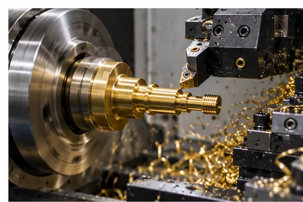
CNC Turning
Rotational parts such as bushings, collars, threaded bodies, pins and fittings. Keeps diameters, shoulders, bores and faces within one rotational feature system.
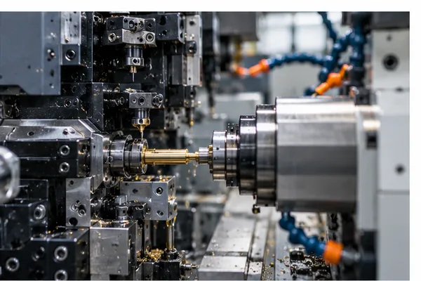
Swiss-Type Turning
Small, slender or feature-dense parts requiring support close to the cutting zone. Useful for drilling, grooving and threading on compact components.
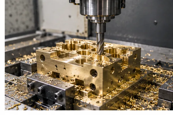
Automatic-Lathe Turning
Suitable for repeatable small turned components when tooling, feature sequence and inspection requirements match the drawing.
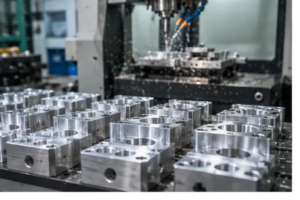
CNC Milling / Turn-Mill
Used for flats, pockets, off-axis holes, mounting faces and non-rotational housings. Turn-mill processing can reduce feature transfers when related features share one datum structure.
Review the Feature Relationships That Control Function
Threads and Knurls
Define thread standard, class or fit, thread depth, blind or through condition, knurl profile and installation direction. These details affect assembly and inspection.
Bores and Outside Diameters
Define critical ID, OD, fit condition, datum reference and concentricity or runout requirement. These relationships control location, rotation and alignment.
Small Holes and Internal Passages
Define diameter, depth, intersections, outlet condition and permitted internal edge condition. These details affect tool access, chip evacuation and inspection visibility.
Wall Thickness
Identify minimum wall, unsupported length, nearby grooves and clamping-sensitive areas. These affect workholding and deformation risk.
Surface Requirements
Separate roughness, cosmetic zones, contact areas and sealing faces. Do not apply one appearance requirement to every surface.
Finishing Allowance
Specify coating, masking, thread condition and whether final dimensions apply before or after finishing.
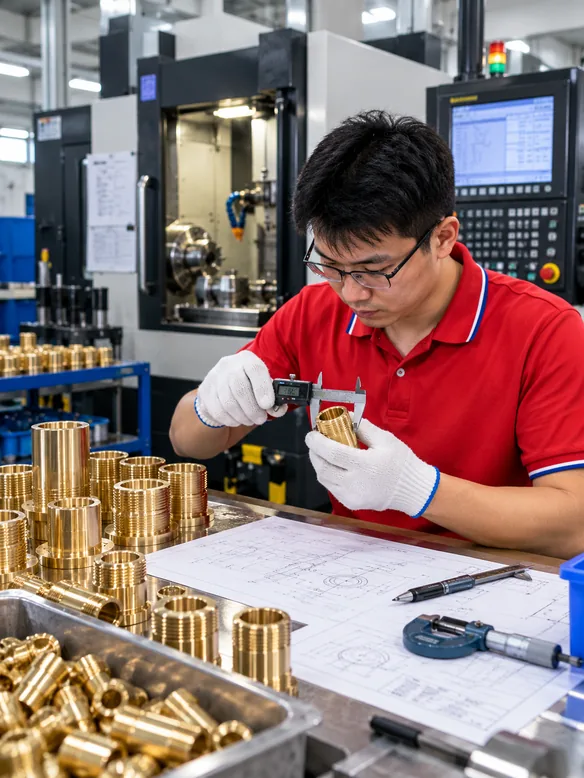
Choose the Part Family by Assembly Role
| Assembly Role | Typical Brass Components | Selection Review Priorities |
|---|---|---|
| Injection-molded or assembled components | Threaded inserts, knurled nuts and flanged inserts | Review thread engagement, knurl geometry, installation direction and host material. |
| Motors and rotating assemblies | Bushings, sleeves, spacers and locating collars | Review ID-to-OD relationship, fit type, concentricity, wall thickness and surface condition. |
| Electrical and electronic assemblies | Contacts, terminals, connector bodies, pins and threaded connection parts | Review material standard, contact geometry, fit, thread condition and finish. |
| Fluid-control hardware | Fittings, adapters, couplings, valve bodies and nozzles | Review thread standard, port geometry, passage cleanliness, sealing datum and service environment. |
| Instruments and sensors | Small turned parts, sleeves, contacts and housings | Review fine-feature geometry, small holes, alignment and appearance zones. |
| General mechanical equipment | Pins, spacers, mounting parts, blocks and custom hardware | Review datum structure, locating dimensions, load path and mating-part compatibility. |
Solve the Brass Part Problems That Affect Assembly
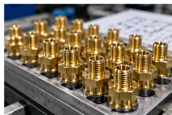
Thread Fit
Buyer problem: A nominal thread callout may not define usable thread depth, lead-in condition, mating fit or final condition after plating.
LuckyHXS response: Review the mating thread, functional thread length, installation direction and finishing allowance. Use functional thread inspection where specified.
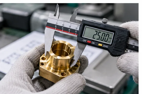
Bore-to-OD Alignment
Buyer problem: A bore and outside diameter can each pass an individual size check while the assembled component still runs off-center.
LuckyHXS response: Review the functional datum structure and inspect the bore, OD and concentricity relationship together.
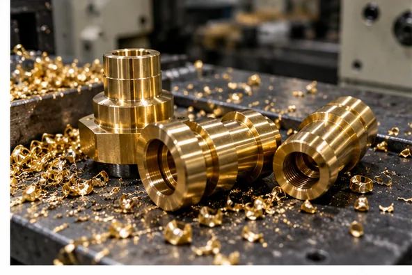
Burrs and Retained Chips
Buyer problem: Chips can remain in blind threads, intersecting holes and internal passages.
LuckyHXS response: Define edge condition, cleaning and screening requirements according to the geometry and final function.
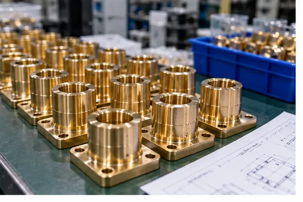
Finish Allowance
Buyer problem: Plating can change thread, bore or contact conditions.
LuckyHXS response: Specify coating type, thickness, masking and whether final dimensions apply before or after finishing.
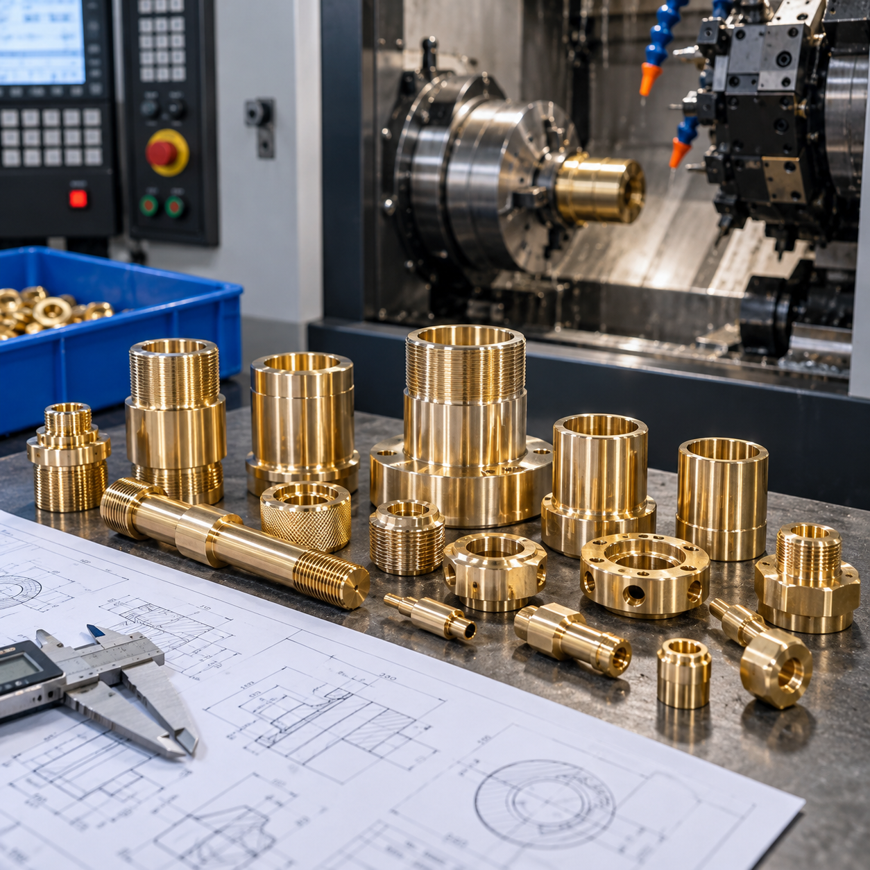
Brass CNC Turned Parts Specifications
- Processes: CNC turning, Swiss-type turning, automatic-lathe turning, CNC milling and turn-mill processing
- Brass material direction: H57, C3602, H59, C3604, H62, H65 and other drawing-specified grades subject to review
- Part forms: inserts, knurled nuts, bushings, sleeves, spacers, pins, contacts, fittings, nozzles, terminals, housings and mounting parts
- Tolerance reference: ±0.01 mm may be discussed for suitable features; final tolerance is confirmed feature by feature
- Drawing formats: PDF, STEP, STP, IGES, IGS, DWG and DXF
- Production type: prototype samples, small batches, repeat production and OEM orders
- Inspection direction: dimensional inspection, thread inspection, CMM or 2D/3D inspection when specified
- Surface direction: as-machined brass, project-specified nickel plating, project-specified gold plating and other reviewed finishing routes
Note: Final specifications depend on the drawing, material, geometry, datum structure, process route and agreed inspection condition.
Choose the Finish Without Losing Functional Fit
Do not select a finish by color alone. Review the base alloy, service environment, mating materials, electrical function and dimensional allowance together.
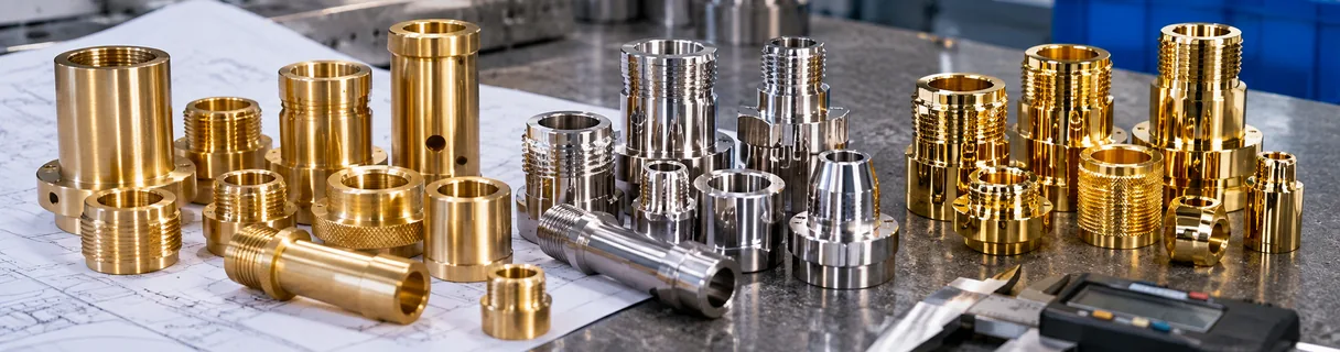
As-Machined Brass
Keeps the machined surface visible and avoids coating build-up. The drawing should identify roughness, cosmetic zones and permitted tool marks where appearance or sealing matters.
Nickel Plating
Can be coordinated for suitable projects. Specify coating requirement, thickness, cosmetic expectation, contact areas, masking and whether thread or bore dimensions apply before or after plating.
Project-Specified Gold Plating
Requires case-by-case review. State plating type, thickness, underlayer, functional contact area, masking and acceptance criteria before feasibility is confirmed.
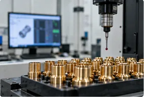
Inspection Built Around Functional Features
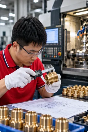
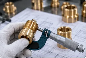
Inspection is most useful when it follows the way the brass part functions. The acceptance plan should identify the datum, final state and critical features that control assembly.
-
Internal and external threads: thread fit, usable depth, entry condition and GO/NO-GO gauge where applicable
-
Bushings and sleeves: critical ID, OD, face relationship, wall condition and drawing-defined concentricity or runout
-
Pins and stepped parts: critical diameters, shoulder positions, straightness and edge condition
-
Small holes and passages: diameter, depth, outlet condition, intersecting edges and retained-chip check
-
Surface and finish: drawing-defined roughness, appearance zone, contact surface and coating-related dimensions
Control Cost by Removing Avoidable Manufacturing Complexity
A DFM review should preserve the part’s function while making non-critical requirements easier to manufacture and inspect.
Brass grade
Unnecessary material requirements or poor chip control can increase machining effort. Use the exact grade required by function.
Tolerance
Applying tight tolerances to every dimension increases machining and inspection effort. Reserve close tolerances for fit, alignment, sealing or movement.
Setup count
Off-axis holes, multiple faces and reversed features may require additional setups. Review whether turn-mill processing can keep related features together.
Threads and small holes
Deep blind threads, tiny holes and intersecting passages increase tool and cleaning demands. Define usable depth and inspection method.
Surface finish
A general cosmetic requirement can create rework. Mark cosmetic, contact and sealing zones separately.
Plating
Coating, masking and post-finish inspection add coordination steps. Specify the final dimensional condition early.
How a Brass CNC Turned Part Moves from Drawing to Production
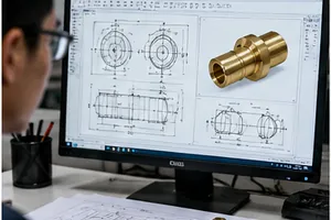
Drawing & Requirement Review
Confirm drawing revision, brass grade, critical dimensions, quantity, finish and assembly function.
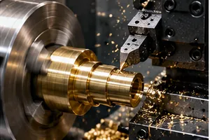
Process & Workholding Planning
Select turning, Swiss-type turning, automatic-lathe turning, milling or turn-mill processing.
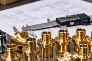
Critical-Feature Planning
Identify threads, fits, concentricity, small holes, thin walls, sealing faces and cosmetic areas.
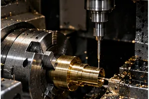
Prototype Machining
Produce the agreed sample or first article for dimensional and functional review.
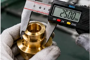
In-Process Inspection
Check agreed critical features during machining and process control.
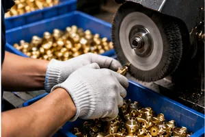
Deburring & Finishing
Apply the agreed post-machining route suitable for the geometry and acceptance criteria.
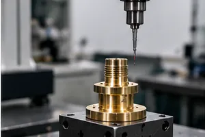
Final Inspection
Evaluate the specified dimensions and functional features before shipment.
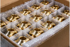
Packaging & Delivery
Use batch-separated packaging and protect finished brass parts for transport.
Where Brass CNC Turned Parts Fit
These application examples describe common selection relationships. They do not automatically represent compliance with an industry standard. State all mandatory regulatory, material and documentation requirements in the project specification.
Injection-Molded Components
Threaded inserts, knurled nuts and flanged inserts.
Motors & Rotating Assemblies
Bushings, sleeves, spacers and locating collars.
Electrical Assemblies
Contacts, terminals, connector bodies and pins.
Fluid-Control Hardware
Fittings, adapters, couplings, valve bodies and nozzles.
Instruments & Sensors
Small turned parts, sleeves, contacts and housings.
General Mechanical Equipment
Pins, spacers, mounting parts, blocks and custom hardware.
Is Brass the Right Material for Your Part?
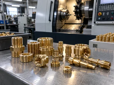
Brass
Often selected for machinability, threaded geometry, electrical components, fittings and a clean machined appearance. Exact properties depend on the alloy and standard.
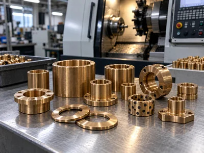
Bronze
May be considered where grade-specific wear, bearing or corrosion requirements are more important than the machining behavior normally associated with free-machining brass.
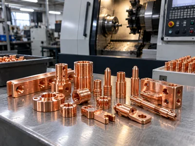
Pure Copper
Provides higher electrical and thermal conductivity than typical brass, but its softer and more adhesive cutting behavior may require different tooling, chip control and cycle planning.
Conclusion: Choose the material by comparing machinability, conductivity, wear, corrosion environment, strength, appearance, finishing compatibility and regulatory requirements.
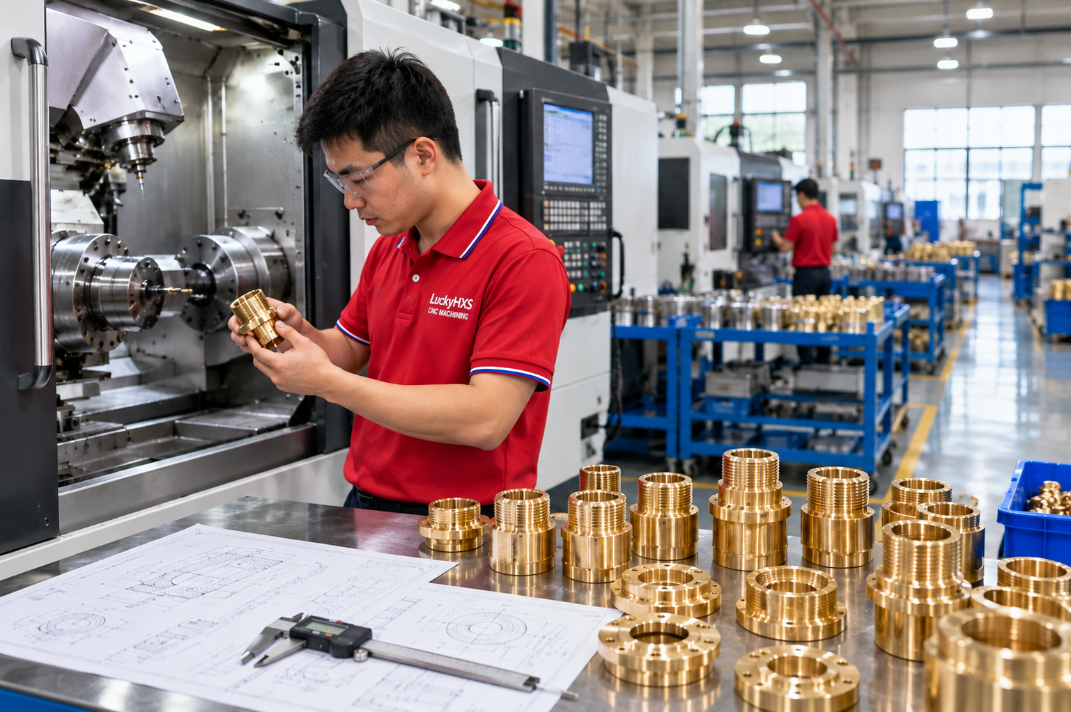
Customer Collaboration at the Shenzhen CNC Facility
Technical communication is part of the manufacturing process. Customer visits, drawing discussions and project reviews help align brass grades, critical features, inspection points and repeat-order requirements before production.
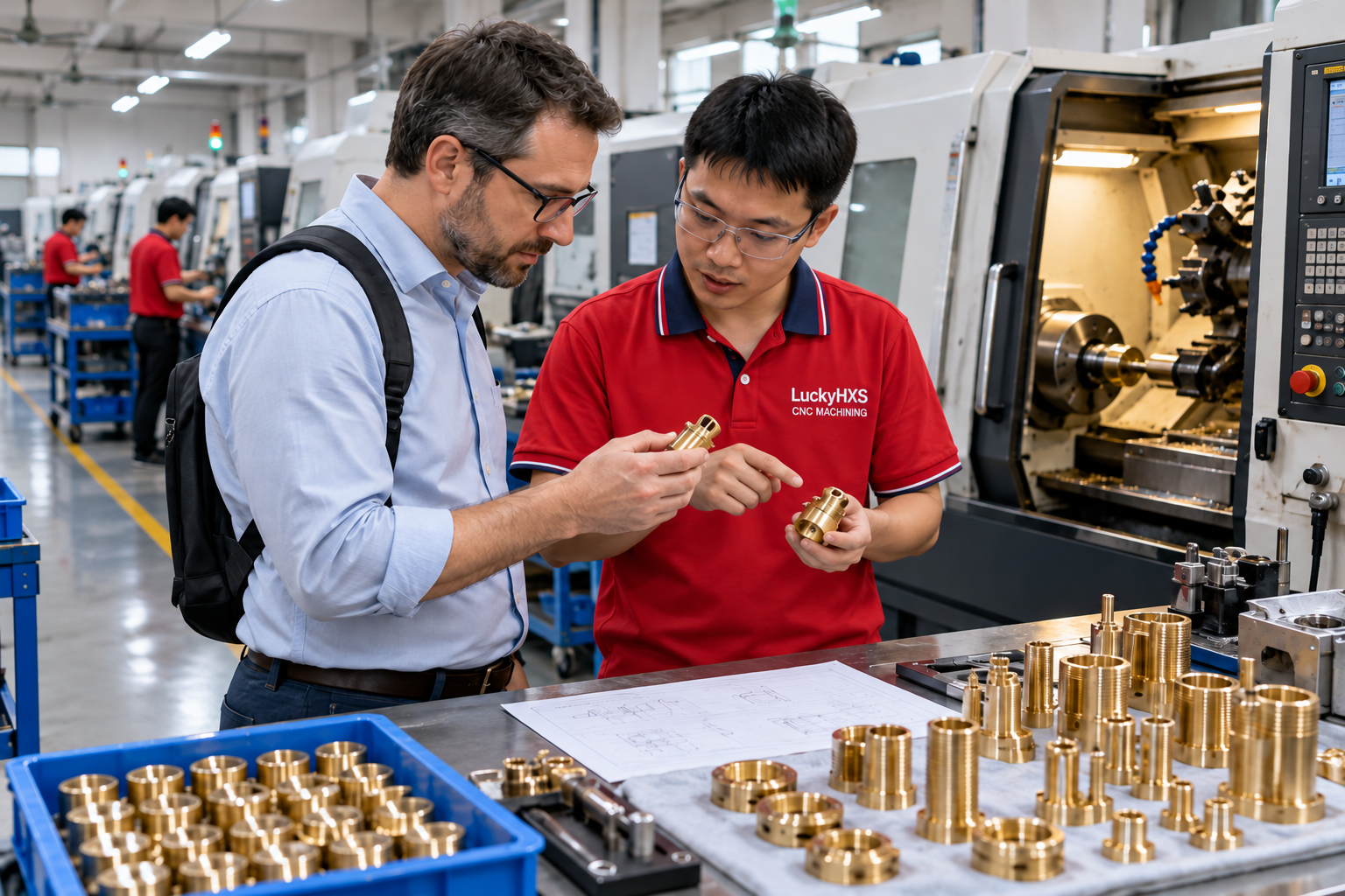
Factory Visit and Process Review
Reviewing CNC equipment, workholding and inspection conditions for a drawing-based component.

Engineering Discussion
Aligning brass grade, thread requirements, datum relationships and finishing allowance.

Project & Partnership Exchange
Coordinating technical requirements, sample review and repeat-production expectations.

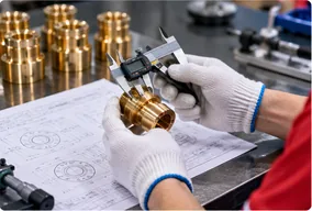
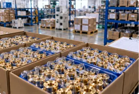
Manufacturing and Inspection in Shenzhen
LuckyHXS CNC manufactures made-to-drawing precision hardware in Shenzhen using CNC Swiss machining, CNC turning, automatic-lathe turning, CNC milling and turn-mill processing.
For brass components, process planning focuses on thread engagement, bore-to-OD relationships, concentricity, small-hole condition, edge quality and finish allowance. The inspection approach is matched to the drawing and the final state in which the part will be used.
- Precision CNC machining division of Shenzhen Hongxiangsheng Technology Co., Ltd.
- 20+ years of industrial machining experience
- Small- and medium-sized precision components
- Prototype-to-batch production support
- Inspection planning based on functional features
- Protective packaging and export coordination
Why Engineers Choose a Drawing-Based Brass Machining Review
We align the manufacturing process with the final assembly function, ensuring critical threads, bores, and finishes meet the actual requirements of the component.
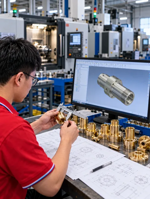
Feature-led process selection
Turning, Swiss-type turning, automatic-lathe turning, milling and turn-mill processing are reviewed around the part geometry.
Material and finish coordination
Brass grade, finishing allowance, thread condition, contact areas and final dimensions are considered together.
Assembly-focused inspection
Threads, bores, outside diameters, concentricity, wall thickness, small holes and sealing faces can receive dedicated attention.
Prototype-to-repeat production support
The approved drawing, sample requirements and inspection priorities can remain visible as the project moves toward repeat production.
Clear technical communication
Drawing revisions, critical dimensions, quantity, finish and documentation requirements are discussed before quotation.
Buyer Guide FAQ
Find answers to common questions about specifying, machining and inspecting brass CNC turned parts.
Which brass grade is easier to machine?
When should I choose Swiss machining?
How should plated brass threads be specified?
What tolerance should be placed on the drawing?
How are burrs and chips controlled?
What information is needed for quotation?
Continue with the Part Type or Process You Need
Prepare a More Useful Brass Part Review
Share the part type, brass grade, critical dimensions, quantity and finishing requirements that define your project. If a drawing number, revision, mating-part requirement or inspection condition is important, include it so the discussion can begin from the correct specification.
Preparation Checklist
- Part family or component function
- Brass grade and material standard
- Drawing revision or sample reference
- Critical threads, bores, diameters and fits
- Quantity or expected repeat-order demand
- Surface finish and masking requirements
- Required inspection or documentation
Request a Brass CNC Turned Parts Review
Send your drawing, sample information or part requirements. Our team will review the material, machining route, critical features, finishing requirements and inspection priorities for your brass CNC turned parts project.