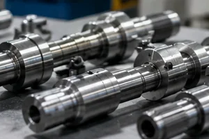
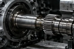
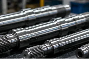
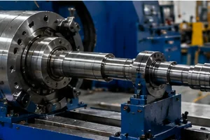

Custom Machined Shafts for Precision Rotating Assemblies

LuckyHxs manufactures custom machined shafts from customer drawings for motors, automation, robotics, industrial machinery and precision rotating assemblies. Our CNC shaft machining focuses on bearing fits, common-axis geometry, runout, straightness, threads, grooves and repeatable production—not diameter alone.

20+ Years CNC Experience 153 Precision Machines Prototype to Batch Production Made to Your Drawing
  • CNC Turning, Swiss & Turn-Mill Processes
  • Bearing Journal & Fit Review
  • Runout & Feature Relationship Control
Request Shaft Machining Quote
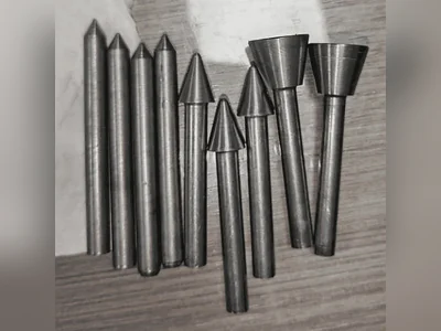
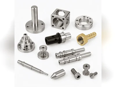
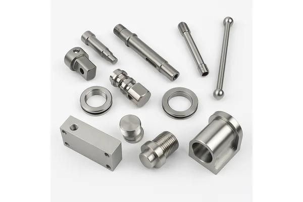
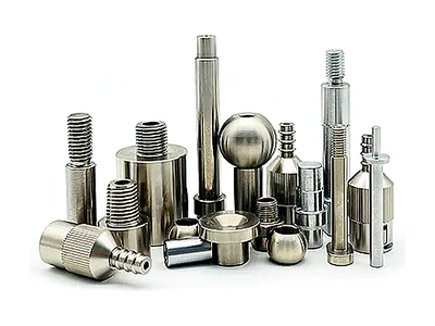
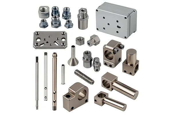
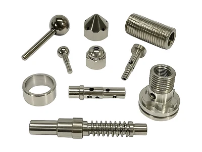
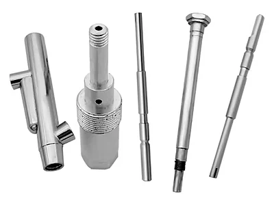
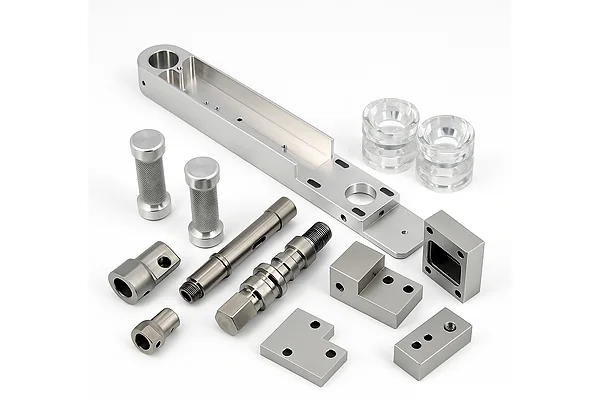
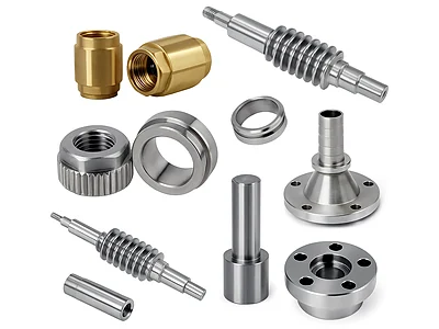
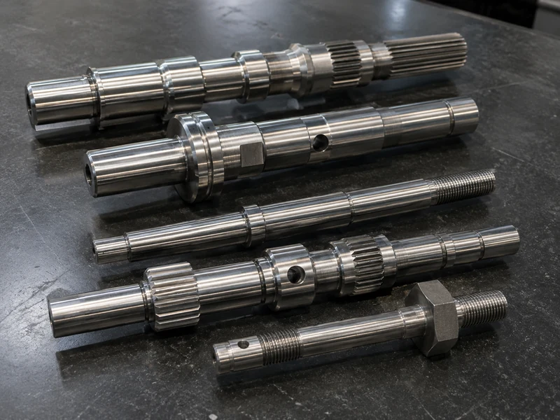
Various Custom CNC Machined Shafts

Custom Machined Shafts at a Glance

Engineering capabilities structured around your specific drawing requirements.

Supply Type

Custom Made-to-Drawing Precision Shafts

Processes

CNC Turning / Swiss / Turn-Mill / Automatic Lathe / Milling for Off-Axis Features

Typical Shafts

Stepped / Motor / Guide / Threaded / Grooved / Hollow / Slender / Multi-Feature

Critical Features Controlled

Journal Fit / Runout / Concentricity / Straightness / Shoulder / Thread / Groove / Surface

Materials

Stainless Steel / Aluminum / Steel / Brass / Copper / Selected Engineering Plastics

Standard Tolerance

Reference ±0.01 mm

*Feature-specific capability depends on material, geometry, and runout requirements.

Buyer Intent Notice

Looking for custom shafts manufactured to your drawing?

LuckyHxs focuses exclusively on made-to-drawing precision shafts for industrial OEM applications. We are not positioned as a stock-shaft retailer for individual consumer purchases or used replacements.

PDF STEP IGES DWG
Functional Zones of a Machined Shaft

What Makes a Machined Shaft a Functional Part?

A shaft works as a system of related features. It may be responsible for rotation, bearing support, guidance, torque transfer, location, or component mounting. Therefore, correct outer diameter (OD) alone does not prove the shaft will perform correctly.

1

Bearing Journal

Controls functional fit, rotational stability, and mating surface condition.

2

Shoulder

Provides axial location and perpendicularity for mounted components.

3

Thread / Retention

Secures assemblies; requires precise location relative to the datum axis.

4

Torque / Orientation Feature

Flats, keyways, or splines that must maintain strict angular alignment.

Machined Shaft Types We Manufacture to Your Drawings

Categorized by shaft geometry, mechanical function, and critical features to align with your engineering intent.

Precision Stepped Shafts

Precision Stepped Shafts

Features multiple outer diameters, bearing journals, and shoulders. Critical for assemblies requiring multiple mounted components.

Watch Point: Common axis concentricity across journals.

Application: Gearboxes, drive systems.

Motor Shafts & Rotor Shafts

Motor & Rotor Shafts

Designed to support rotor fit and rotational stability. Often includes circlip grooves, flats, or cross holes.

Watch Point: Runout and bearing fit precision.

Application: Electric motors, encoders.

Guide, Locating & Alignment Shafts

Guide & Alignment Shafts

Provides continuous guidance, sliding, or support. Differs from pins by requiring controlled straightness over length.

Watch Point: Straightness and surface finish.

Application: Automation, linear guidance.

Threaded Shafts & Stud Shafts

Threaded & Stud Shafts

Incorporates external threads, entry chamfers, and relief grooves relative to functional shoulders.

Watch Point: Thread-to-shaft concentricity.

Application: Actuators, tensioning systems.

Grooved, Slotted & Milled-Flat Shafts

Grooved & Milled-Flat

Features flats, keyways, slots, or retaining grooves for torque transfer or specific angular orientation.

Watch Point: Angular relationship to axis.

Application: Drive assemblies, pulleys.

Hollow Shafts & Precision Tubular Shafts

Hollow Tubular Shafts

Bored or through-bore shafts requiring strict control over inner diameter (ID) and outer diameter (OD).

Watch Point: Bore-to-OD concentricity, wall thickness.

Application: Fluid routing, lightweight drives.

Long Slender Shafts & Small-Diameter Shafts

Long Slender Shafts

Needle shafts or miniature rods where length-to-diameter ratio demands specialized Swiss machining or support.

Watch Point: Deflection and straightness.

Application: Micro motors, precision instruments.

Custom Multi-Feature Shafts & Spindles

Custom Multi-Feature

Complex spindles combining multiple ODs, bores, threads, cross holes, and off-axis milled features.

Watch Point: Functional datums across features.

Application: Custom robotics, specialized machinery.

Custom CNC Machined Shafts for Rotating & Motion Assemblies

A selection of drawing-based shafts demonstrating our capability across various geometries and materials.

Stepped Shaft Component Precision Motor Shaft Threaded Shaft Assembly Part Shaft with Keyway Cross-Hole Machined Shaft Hollow Tubular Shaft Long Slender Guide Shaft Spline-End Torque Shaft Multi-Feature Spindle Stainless Steel Rotor Shaft Aluminum Alignment Shaft Complex Machined Shaft Component

Different Shaft Types Solve Different Mechanical Functions

Selecting the right manufacturing approach depends on what the shaft is expected to do in the final assembly.

Shaft Type Primary Function Buyer Concern
Stepped Shaft Multiple bearing support Common axis concentricity
Motor Shaft Rotor location & high RPM Runout & dynamic stability
Guide Shaft Linear sliding / support Straightness & surface finish
Spline Shaft High torque transfer Tooth geometry fit
Threaded Shaft Axial retention / actuation Thread-to-datum alignment
Various Shaft Types and Functions

Materials for Custom Machined Shafts

Material selection directly impacts machining strategy, burr control, and post-processing dimensional stability.

Stainless Steel

303 / 304 / 316 / 316L

Typical for precision shafts, guide shafts, and motor components requiring corrosion resistance.

Buyer Watch: Work hardening during machining, burr control on cross holes, and final journal surface condition.

Aluminum

6061 / 6063 / 6082 / 7075

Used for lightweight shafts, instrument components, and low-load motor shafts.

Buyer Watch: Surface damage during handling, and dimensional changes resulting from anodizing buildup on bearing fits.

Free-Machining Steel

1214 / 1215

Excellent for high-volume repeat turned components, pins, and stud shafts.

Buyer Watch: Requires appropriate plating or surface treatment to prevent rust in application.

Brass & Copper

H59 / H62 / C3604 / Copper

Brass for instrument shafts; Copper strictly for conductive or specialized components.

Buyer Watch: Material softness requires careful workholding to prevent deformation during turning.

Specialized Materials

Titanium / Engineering Plastics (POM, Nylon, PTFE)

Titanium is subject to project-specific review. Plastics are suitable only for low-load, insulating, or specialized guide shaft components according to drawing review.

How Are Precision Machined Shafts Manufactured?

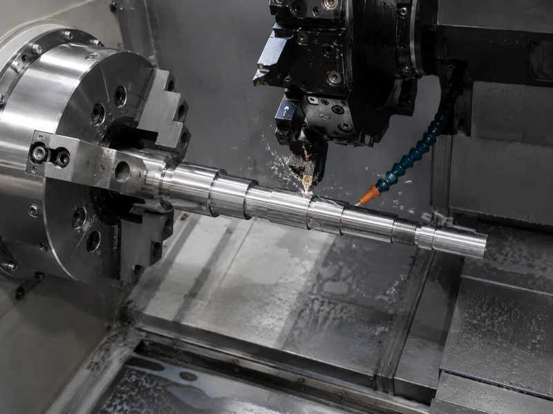
We choose the machining process based on shaft geometry, length-to-diameter ratio, and functional datums—not from a generic "precision" label.

Standard Cylindrical Shaft

→ Routed to CNC Turning for optimal journal control.

Long Small-Diameter Shaft

→ Routed for Swiss Machining Evaluation to minimize deflection.

Shaft With Flats / Slots / Cross Holes

→ Routed to Turn-Mill Evaluation to maintain angular relationships without secondary setups.

Ask Which Process Fits Your Shaft
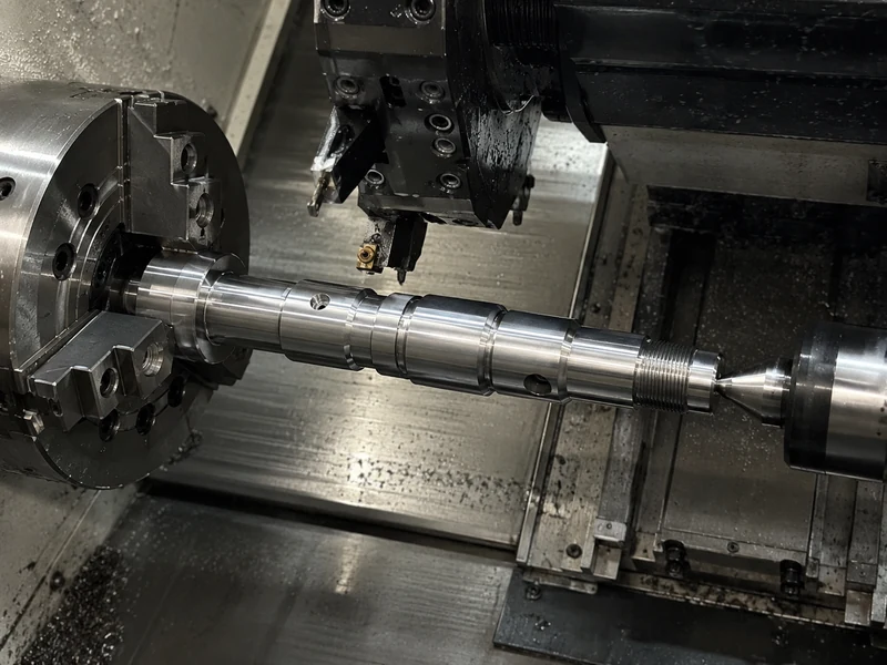
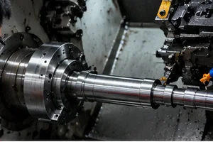
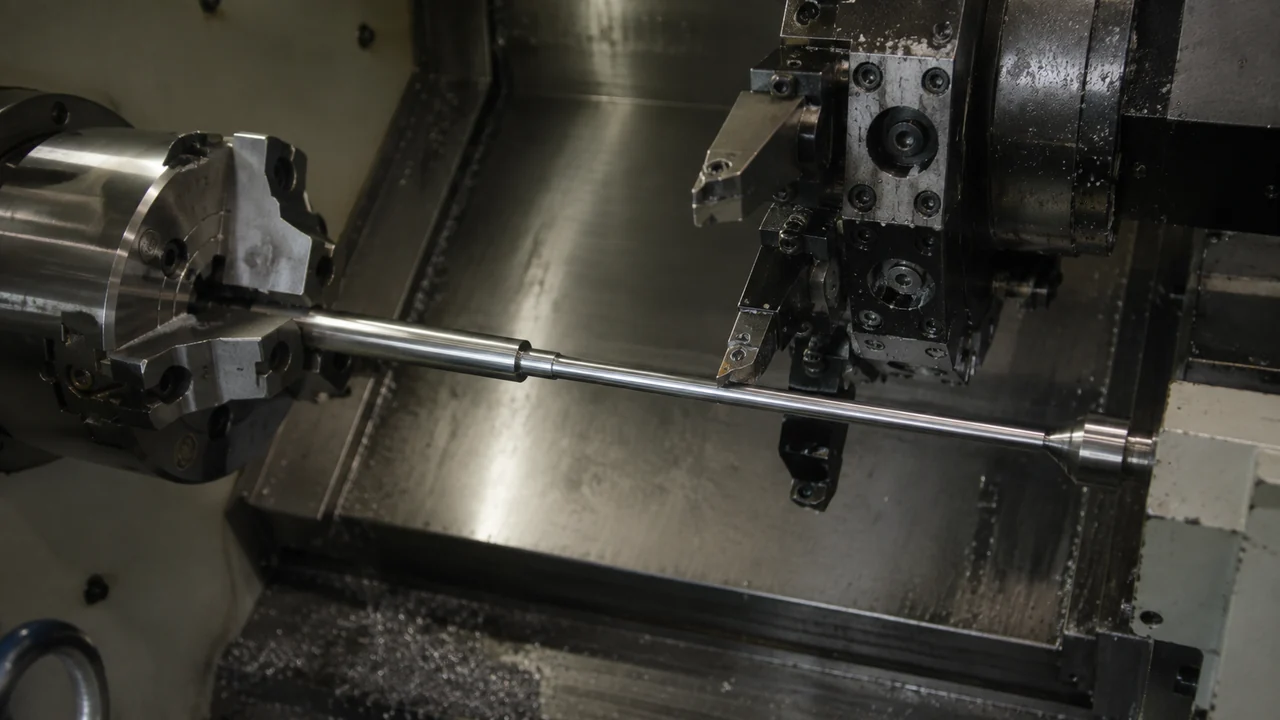
CNC Machining Process for Shafts

Why Machined Shafts Fail Even When Diameters Pass

Common risks buyers face when ordering custom shafts based purely on dimensional checks rather than functional assembly intent.

01

Bearing Fits Are Dimensionally Correct but Functionally Wrong

Affects: Motor & Spindle Shafts. Consequence: Premature bearing wear or installation failure.

02

Multiple Journals Lose Concentricity & Runout Control

Affects: Stepped Shafts. Consequence: Vibration and uneven rotation in the assembly.

03

Prototype-to-Production Shaft Quality Drifts

Affects: Repeat Batch Orders. Consequence: Assembly lines stall due to inconsistent fits.

4. Long Slender Shafts Lose Straightness

Consequence: Binding in linear guides or extreme runout at far ends.

5. Shaft Shoulders Fail Axial Location

Consequence: Mounted components sit misaligned or non-perpendicular.

6. Journal Surface Damages Seals

Consequence: Incorrect roughness tears lip seals, causing leaks.

7. Threads Pass Individually but Fail Position

Consequence: Nuts bind against shoulders due to poor thread runout.

8. Flats & Cross Holes Lose Angular Relation

Consequence: Pulleys or gears mount at the wrong timing angle.

9. Hollow Shafts Have Uneven Wall Geometry

Consequence: ID and OD pass, but bore offset causes imbalance.

Bearing Journals Pass Size Checks but Still Fail Functional Fits

The Challenge

You may check that "Journal Diameter = PASS", but the final bearing fit is also affected by the tolerance zone, bearing seat geometry, surface condition, and shoulder perpendicularity. Correct diameter ≠ Correct functional fit.

Potential Problems

  • Bearing too loose (creep)
  • Excessive interference
  • Premature wear / heat
  • Vibration

LuckyHxs Approach

  • Review fit-related dimensions
  • Confirm critical tolerance zones
  • Review shoulder relationship
  • Inspect finished functional seat
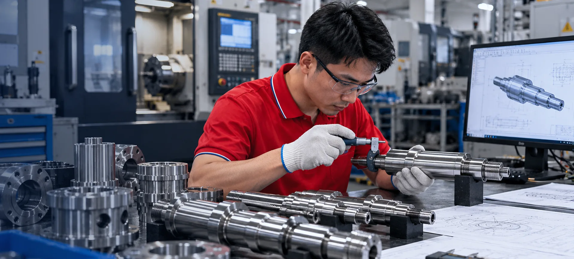
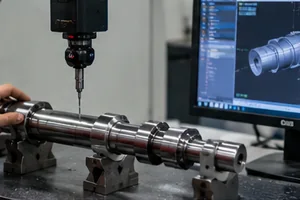
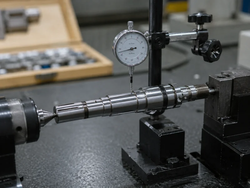
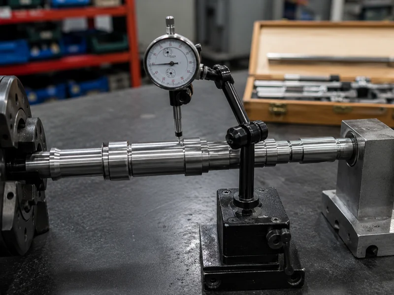
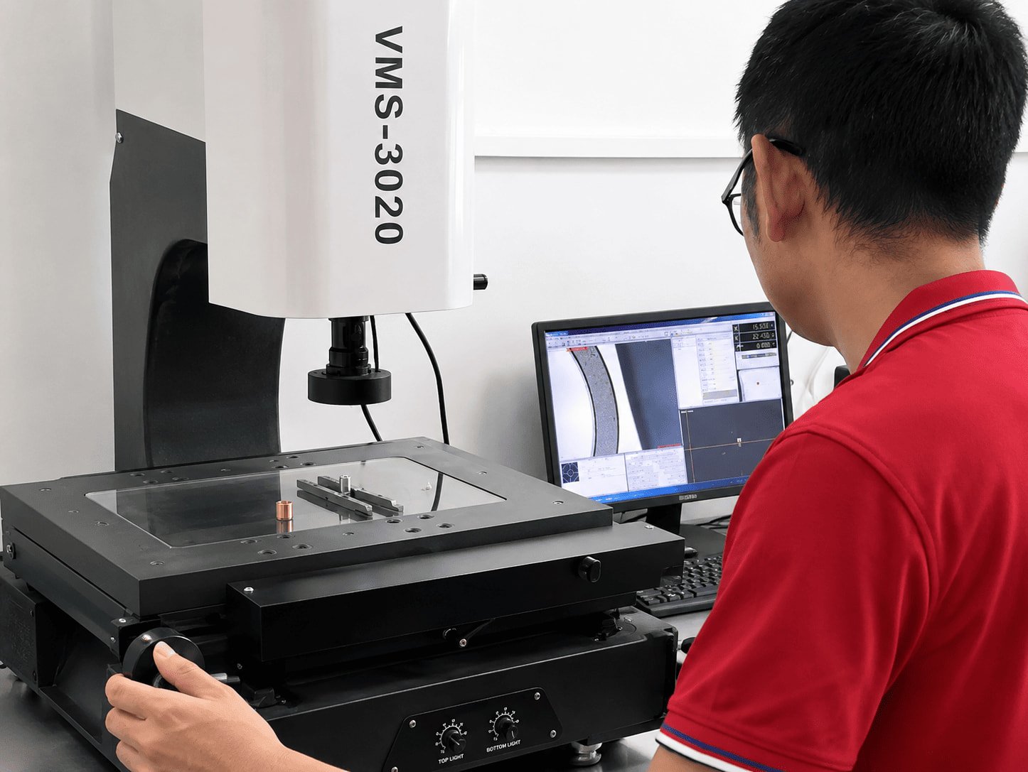
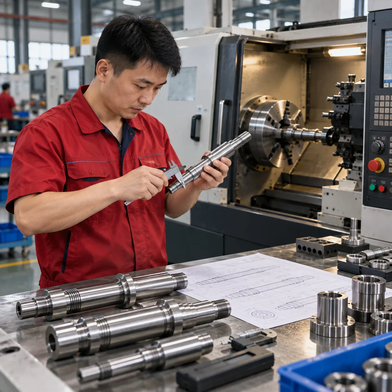
Bearing Journal Inspection
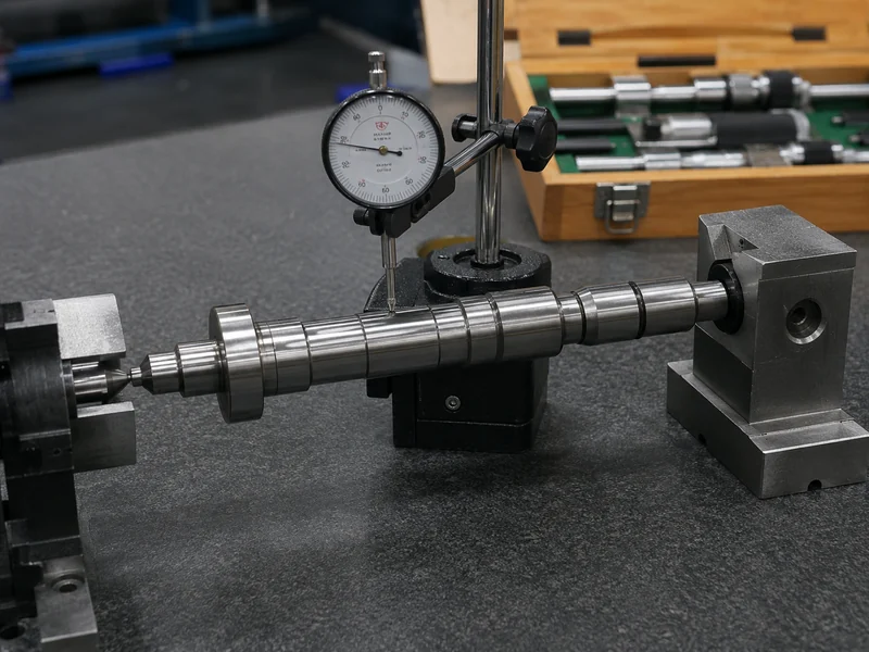
Runout and Concentricity Check

Multiple Journals Pass Individually but Lose a Common Rotational Axis

The Challenge

Journal A passes. Journal B passes. But the Common Axis fails. This happens on stepped shafts and motor shafts due to multiple setups, datum changes, or bar condition. Individual Diameters PASS ≠ Common Rotational Axis PASS.

What We Check

  • Concentricity to datum
  • Radial Runout
  • Roundness
  • Shoulder perpendicularity

LuckyHxs Approach

  • Define primary rotational datum
  • Reduce unnecessary datum transfers
  • Review machining sequence
  • Verify functional geometry

Prototype Passes, but Runout & Feature Relationships Drift in Production

The Challenge

The first article is perfect, but in repeat production, journal sizes drift, runout increases, and flat positions change due to tool wear, material lot variations, or cutting heat. Prototype Approval ≠ Automatic Repeat-Batch Stability.

Why It Happens

  • Tool wear & offset changes
  • Bar stock condition variations
  • Collet / chuck wear
  • Deburring variation

LuckyHxs Approach

  • First Article Verification
  • In-Process Inspection
  • Tool Condition Monitoring
  • Repeat-Order Requirement Retention
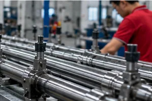
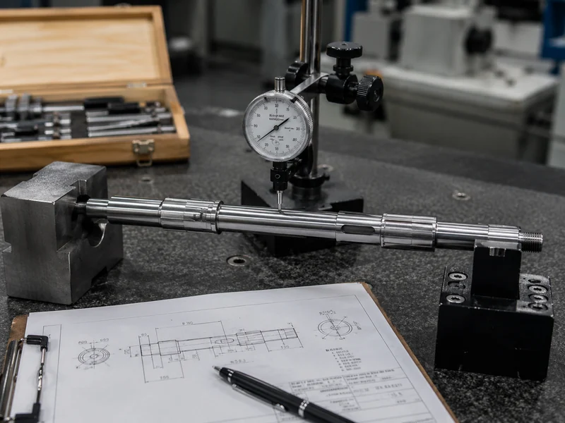
Batch Shaft Inspection

A Bearing Seat Is More Than a Diameter

Journal Diameter + Surface + Shoulder + Rotational Geometry must be reviewed together based on your drawing.

Diameter

Determines the fundamental fit range (interference vs clearance).

Roundness

Ensures even contact pressure inside the bearing or housing.

Surface

Impacts assembly ease and prevents seal damage during rotation.

Shoulder Face

Must be perpendicular to avoid cocking the bearing race.

Shoulder Position

Controls the final axial location of the mounted component.

Diameter, Runout and Straightness Measure Different Shaft Risks

Understanding which geometric control matters most for your assembly.

Diameter

"Is the journal the correct size?"

Controls the localized fit. It does not guarantee the journal is centered on the shaft.

Runout

"Does the surface rotate consistently around the datum axis?"

Critical for high-speed motor shafts to prevent vibration and uneven seal wear.

Common Axis / Concentricity

"Do related journals share the required rotational relationship?"

Crucial for stepped shafts where bearings at opposite ends must align.

Straightness

"Does a long shaft remain aligned over its length?"

Important for guide shafts to prevent binding in linear bearings.

Roundness

"Is the shaft locally circular enough?"

A shaft can have the right diameter but be slightly oval, causing tight spots.

Long, Small-Diameter Shafts Need More Than Tight Diameter Tolerances

Near-chuck diameter PASS does not prove the far end of a long shaft will run correctly.

Long Slender Shaft Machining

The Deflection Risk

High length-to-diameter ratios cause the material to push away from the cutting tool, resulting in taper, chatter, and poor surface finish in the center of the shaft.

Swiss Machining Evaluation

For slender geometries (e.g., needle shafts, small motor shafts), we evaluate Swiss machining where the guide bushing supports the material directly at the cutting point.

Bar Straightness Impact

The straightness of the raw bar stock heavily influences the final runout of a long shaft. Support strategies and machining sequences are critical.

Threads, Grooves & Torque-Transfer Features Must Match the Shaft Datum

Correct feature size does not automatically mean correct feature location.

THREADS

  • Review: Thread Gauge, Effective Length, Thread Runout, Entry Chamfer.
  • Risk: Shoulder distance errors prevent nuts from seating fully.

GROOVES

  • Review: Width, Depth, Position, Retaining-Ring Location.
  • Risk: Incorrect groove position causes axial play in the assembly.

FLATS & KEYWAYS

  • Review: Width, Depth, Angular Position relative to other features.
  • Risk: A flat can be the right size but at the wrong angle, misaligning drive components.

CROSS HOLES & SPLINES

  • Review: Centerline position, Spline fit (where specified).
  • Risk: Off-center cross holes prevent pin insertion.

Final Shaft Fits Must Be Reviewed After the Last Manufacturing Step

Does your drawing dimension apply before finishing or after finishing? Post-processing can alter critical fits.

Plating & Anodizing: Zinc, Nickel, or Anodizing adds material thickness, potentially pushing a passing journal out of tolerance.

Heat Treatment: Induces stress and potential warping. (Subject to project-specific review).

Grinding: Required only when tolerances exceed turning capabilities. (Subject to project-specific review).

Shaft Surface Finish Comparison

Inspect Shafts Around How They Rotate and Assemble

From First Article to Repeat Batch Production.

12-Step Quality Flow

1 Drawing Review
2 Material Confirmation
3 Functional Journal ID
4 Fit / Datum Review
5 Machining Route Selection
6 First Article Verification
7 Journal Diameter Inspection
8 Runout / Concentricity Review
9 Thread / Groove Inspection
10 Surface Review
11 Final Batch Verification
12 Repeat-Order Retention

Where Custom Machined Shafts Are Used

Motors & Micro Motors

Concern: Runout + Bearing Journal

Robotics

Concern: Fit + Orientation

Industrial Automation

Concern: Straightness + Surface

Motion Systems

Concern: Concentricity + Threads

Precision Instruments

Concern: Micro-features + Finish

Automotive & EV

Concern: Batch repeatability

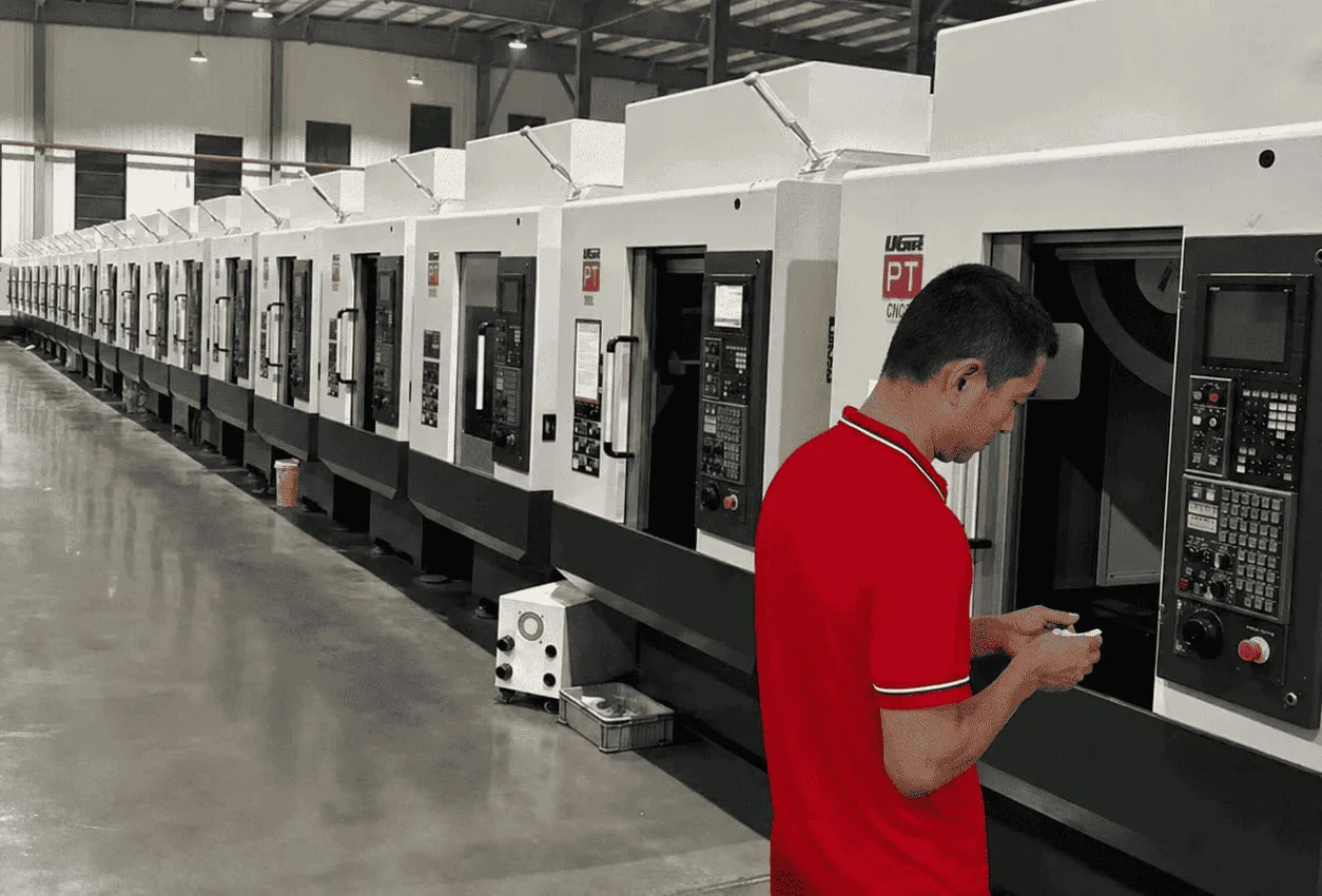
A CNC Manufacturing Partner You Can Verify

Real production, real inspection, real factory.

Certificates & Compliance Documents

  • ISO 9001 Certificate
  • CE Certificate
  • REACH Certificate
  • ROHS Certificate

Verification Support

  • Quality system documentation
  • Material & compliance documents
  • Inspection records when required
  • Project documentation available for review
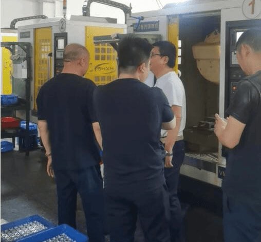
Factory Visit
Factory Visit
Production Review
Production Review
Technical Discussion
Quality Review
Quality Review

See How LuckyHxs CNC Parts Are Machined and Inspected

See How LuckyHxs CNC Parts Are Machined and Inspected

What Are Machined Shafts? Meaning, Types & Applications

In mechanical equipment, a shaft is generally a cylindrical mechanical component used to support rotation, guide motion, locate rotating elements or transmit torque depending on the assembly design. A machined shaft is produced to controlled diameters, shoulders, journals, threads and other features according to an engineering drawing.
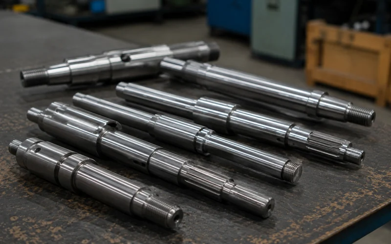
Types of Machined Shafts

What Does a Shaft Do?

  • Rotation: Acts as the central axis for spinning components.
  • Bearing Support: Provides the precision journal for bearings to seat against.
  • Torque Transfer: Uses keyways, flats, or splines to transmit rotational force.
  • Guidance: Provides a straight, smooth surface for linear bearings to travel along.

Common Machined Shaft Types

Stepped Shaft

Function: Multiple bearings / mounted components. Buyer Watch: Common axis + shoulder position.

Spline Shaft

Function: Torque transfer / indexed engagement. Buyer Watch: Spline form + fit + mating component.

The correct shaft type should be selected around load, rotation, mating components, fit and geometry—not simply the nominal shaft diameter.
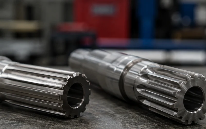
What Is a Spline Shaft? Straight-Sided vs. Involute Splines

A spline shaft uses multiple longitudinal teeth or grooves to engage a matching component and transfer torque or maintain angular positioning. When torque requirements exceed what a simple keyway or flat can handle, splines distribute the load across multiple engagement surfaces.

Straight-Sided vs Involute Spline Shaft

Straight-Sided Spline

Features parallel-sided tooth geometry.

Project Must Confirm:
  • Number of Teeth
  • Major / Minor Diameter
  • Tooth Width & Fit
  • Effective Length

Involute Spline

Features an involute tooth profile, often self-centering under load.

Project Must Confirm:
  • Standard (ANSI/DIN/ISO)
  • Module / DP
  • Pressure Angle
  • Fit / Class

Important: LuckyHxs reviews custom spline shafts according to customer drawings. For specific ANSI, DIN, ISO, or SAE spline standards, the exact standard, fit class, and inspection requirements must be confirmed prior to quotation.

How Do You Choose a Machined Shafts Manufacturer?

A buyer's checklist for evaluating custom CNC shaft machining partners.

  • 1. Can They Review Functional Bearing Fits? (Or do they just check OD?)
  • 2. Can They Control Multiple Journals Around One Axis? (Critical for stepped shafts).
  • 3. How Do They Inspect Runout? (Dial indicators, V-blocks, specific datum references).
  • 4. How Do They Handle Long Slender Shafts? (Do they evaluate Swiss machining?)
  • 5. Can They Control Shoulder Position & Face Geometry? (Perpendicularity matters).
  • 6. Can They Machine Threads, Grooves, Flats and Cross Holes? (Turn-Mill capabilities).
  • 7. How Is Repeat-Batch Drift Monitored? (Tool wear management).

Frequently Asked Questions About Machined Shafts

What is a machined shaft?
A machined shaft is a custom cylindrical component produced via CNC turning to specific drawing tolerances. It typically features journals, shoulders, threads, or grooves to support rotation, guide motion, or transmit torque in an assembly.
What is the difference between a shaft and a pin?
A shaft generally emphasizes continuous rotation, guidance, bearing support, or torque transfer. A pin generally emphasizes locating, retention, or static connection. The exact definition depends on the final assembly function.
Can you machine long and small-diameter shafts?
Yes, subject to geometry, material, straightness, runout, and process review. For slender shafts with high length-to-diameter ratios, we evaluate Swiss machining to prevent deflection during cutting.
Can you manufacture spline shafts?
LuckyHxs reviews spline shaft projects according to customer drawings. For involute, straight-sided, ANSI, DIN, ISO or other specified spline systems, the exact standard, fit, tooth geometry, and inspection requirements must be confirmed before quotation.
How much do custom machined shafts cost?
There is no fixed price for a drawing-based machined shaft. Cost depends on material, raw bar size, tolerances, runout requirements, threads, grooves, flats, machining time, quantity, surface finishing, and inspection methods. An engineering drawing is required for an accurate quote.

Need Shafts That Rotate, Fit & Assemble the Way the Drawing Intended?

Send your 2D/3D drawing, material, quantity, bearing-journal requirements, runout, concentricity, threads, grooves, flats, surface finish and inspection requirements. LuckyHxs will review the shaft geometry and machining route before quotation.

Talk to Our Engineering Team

Or email drawings directly to: admin1@lucky-hxs.com