

Custom Brass CNC Machining Services from a Precision Parts Manufacturer
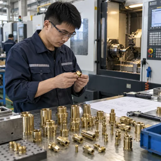
LuckyHXS manufactures custom brass components from customer drawings using CNC turning, Swiss-type turning, milling and turn-mill processing. We focus the machining and inspection plan on the features that affect assembly: threads, bores, outside diameters, concentricity, small holes, edges and surface condition.
- Custom inserts, bushings, pins, fittings, connectors and milled components
- Brass grades reviewed around machinability, function and finishing requirements
- Feature-specific inspection for threads, fits, concentricity and edge condition
What We Machine in Brass
Brass combines useful machinability with corrosion resistance, electrical conductivity and a clean finished appearance, but the result still depends on the exact alloy, geometry and process route. LuckyHXS produces made-to-drawing brass parts for threaded assemblies, rotating fits, electrical connections, fluid-control hardware, instruments and general mechanical assemblies.
Part Forms
Threaded inserts, knurled nuts, bushings, sleeves, spacers, pins, contacts, fittings, nozzles, terminals, housings and mounting parts.
Machining Routes
CNC turning, Swiss-type turning, automatic-lathe turning, CNC milling and turn-mill processing.
Material Direction
H57, C3602, H59, C3604, H62, H65 and other drawing-specified brass grades are reviewed according to the applicable standard and project requirements.
Critical Features
Threads, bore-to-OD relationships, concentricity, wall thickness, small holes, sealing faces, edge condition and finish allowance.
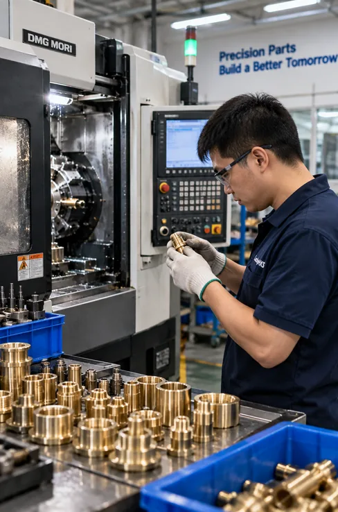
Custom Brass Parts We Machine to Drawing Requirements
Choose the part family closest to your drawing. The final machining route, alloy, inspection points and finishing allowance are reviewed around the component’s functional features.

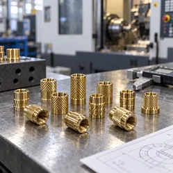
Brass Threaded Inserts & Knurled Nuts
Internal threads, external knurls, flanges, blind holes and through-hole structures for molded or assembled components.
Selection cues: thread specification and installation method.
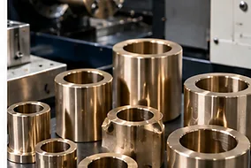
Brass Bushings, Sleeves & Spacers
Unthreaded bores, thin walls, flanged profiles and controlled ID-to-OD relationships for rotating or locating assemblies.
Selection cues: fit type and bore-to-OD relationship.
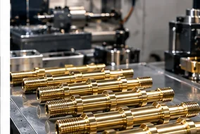
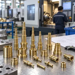
Brass Pins, Contacts & Precision Turned Parts
Straight, stepped, grooved, threaded or cross-drilled parts where diameter, length, straightness and edge condition influence assembly.
Selection cues: critical diameter and end-feature geometry.
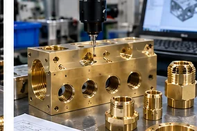
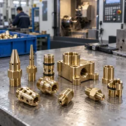
Brass Fittings, Adapters & Couplings
Components with internal or external threads, connecting bores, mating faces and compact multi-diameter profiles.
Selection cues: thread standard and sealing or mating datum.
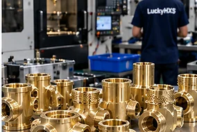
Brass Valve Bodies, Nozzles & Fluid Components
Drawing-defined ports, orifices, passages and sealing surfaces for compact fluid-control hardware.
Selection cues: passage geometry and sealing-surface requirements.
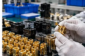
Brass Electrical Connectors & Terminals
Machined contact and connection structures where alloy identification, fit, surface condition and finishing requirements must be coordinated.
Selection cues: contact geometry and specified material standard.
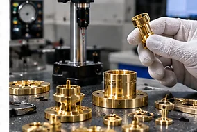
Brass Instrument, Sensor & Micro Components
Small custom components with fine features, controlled fits, small holes or appearance-sensitive surfaces.
Selection cues: critical feature size and assembly relationship.
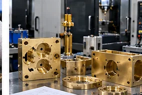
Custom Brass Housings, Blocks & Mounting Parts
Milled or turn-milled structures with pockets, mounting holes, multiple faces and drawing-defined datums.
Selection cues: datum structure and milling-access requirements.
Different Geometry Calls for Different Machining Decisions
A brass part can look simple while combining several functional requirements. Threads may need to align with a bore, a thin wall may need protection during clamping, or a plated surface may change the final fit. Review the entire feature relationship rather than treating each dimension independently.
- Knurled and threaded inserts for molded or assembled components
- Sleeves and bushings with controlled bore and outside diameter
- Stepped pins and small turned parts with secondary features
- Fittings and adapters with threads, bores and mating faces
- Nozzles and fluid components with internal passages
- Milled brackets, housings and mounting parts with multiple datums

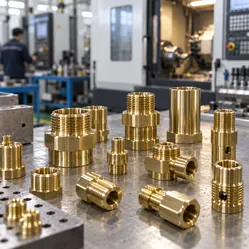
Select the Brass Grade Around Machining and Service Requirements
The alloy designation affects chip formation, tool behavior, cycle planning, surface appearance and the finished part’s suitability for its operating environment. State the full grade and material standard whenever the drawing or end use requires a specific composition.
| Material Direction | Machining Consideration | When to Review It |
|---|---|---|
| H57 or C3602 | General brass options represented in the current material range. Confirm the exact standard, composition and functional requirement rather than relying on a short grade name alone. | Review when the drawing already names one of these grades or when the material must match an existing component specification. |
| H59 or C3604 | Often considered where machining efficiency and stable chip control are important. Compared with softer copper-rich materials, these grades can reduce the tendency for material to adhere to the cutting tool. | Review for turned inserts, bushings, pins, threaded parts and other geometry where machinability is a central concern. |
| H62 or H65 | Softer brass options may require more attention to tool condition, chip evacuation, surface marks and cycle planning. | Review when formability, appearance or a drawing-specific material requirement takes priority over maximum machining efficiency. |
| Drawing-Specified Lead-Free or DZR Brass | Lead-free and dezincification-resistant requirements are grade- and standard-specific. They must not be inferred from the word “brass.” | State the exact alloy, standard, service environment and required documentation for case-by-case sourcing and machining review. |
Material selection must also account for the operating environment, electrical function, wear, mating material, finishing process and any regulatory requirement that applies to the finished assembly.
Match the Machining Route to the Part Geometry
The most suitable process depends on how the part is held, where the critical features sit and how many setups are needed to complete them.
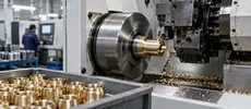
CNC Turning
A practical route for rotational parts such as bushings, collars, threaded bodies, pins and fittings. Turning keeps diameters, shoulders, bores and faces within one rotational feature system.
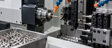
Swiss-Type Turning
Well suited to small or slender components that need support close to the cutting zone. It is especially useful when a part combines several turned features with drilling, grooving or threading.

Automatic-Lathe Turning
Applicable to suitable small turned components with repeatable geometry. Tooling, feature sequence and inspection requirements still need to match the drawing.

CNC Milling and Turn-Mill Processing
Used for flats, pockets, off-axis holes, mounting faces and non-rotational housings. Turn-mill processing can reduce feature transfers when turned and milled geometry belong to the same datum structure.
Process selection is not based on the part name alone. A fitting, connector or housing may require a different route when its datum, hole orientation or tolerance relationships change.
Define the Features That Control Function and Assembly
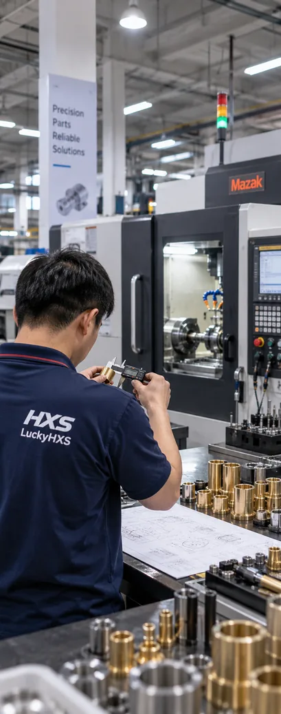
Custom brass CNC machining starts with the drawing, but not every dimension carries the same manufacturing risk. Identifying the functional features helps align the machining route and inspection plan with the way the part will be assembled.
| Feature | Typical Drawing Definition | Why It Matters |
|---|---|---|
| Overall Geometry | Diameter, length, flats, flange, shoulder, pocket and mounting-face relationships. | Determines whether the part is primarily turned, milled or produced through a combined route. |
| Threads and Knurls | Thread standard, class or fit, thread depth, blind or through condition, knurl profile and installation direction. | Affects assembly torque, pull-out behavior, mating-part compatibility and inspection method. |
| Bores and Outside Diameters | Critical ID and OD sizes, fit condition, datum reference and concentricity requirement. | Controls rotation, location, press fit, clearance and alignment in the final assembly. |
| Small Holes and Internal Passages | Hole diameter, depth, intersection, outlet condition and permitted internal edge condition. | Influences tool access, chip evacuation, inspection visibility and fluid or electrical function. |
| Wall Thickness | Minimum wall, unsupported length, nearby grooves and clamping-sensitive surfaces. | Influences deformation risk, workholding strategy and cutting sequence. |
| Surface Requirement | Surface roughness, cosmetic zone, tool-mark limitation, contact area and sealing face. | Determines which surfaces need process-specific control rather than a general appearance requirement. |
| Finishing Allowance | Coating type, functional areas, masking, thread condition and final acceptance requirement. | Helps prevent the finish from changing a fit, thread or contact surface unexpectedly. |
Diameter, length, flats, flange, shoulder, pocket and mounting-face relationships.
Determines whether the part is primarily turned, milled or produced through a combined route.
Thread standard, class or fit, thread depth, blind or through condition, knurl profile and installation direction.
Affects assembly torque, pull-out behavior, mating-part compatibility and inspection method.
Critical ID and OD sizes, fit condition, datum reference and concentricity requirement.
Controls rotation, location, press fit, clearance and alignment in the final assembly.
Hole diameter, depth, intersection, outlet condition and permitted internal edge condition.
Influences tool access, chip evacuation, inspection visibility and fluid or electrical function.
Minimum wall, unsupported length, nearby grooves and clamping-sensitive surfaces.
Influences deformation risk, workholding strategy and cutting sequence.
Surface roughness, cosmetic zone, tool-mark limitation, contact area and sealing face.
Determines which surfaces need process-specific control rather than a general appearance requirement.
Coating type, functional areas, masking, thread condition and final acceptance requirement.
Helps prevent the finish from changing a fit, thread or contact surface unexpectedly.
For suitable features, a machining tolerance reference of ±0.01 mm may be discussed. Final tolerances must be confirmed feature by feature according to material, size, geometry, datum structure, process route and inspection method.
Four Issues That Deserve Attention Before Production
Many brass-part problems begin with a feature relationship that was not clearly defined at the drawing-review stage. The following issues have a direct effect on assembly and inspection.
Thread Fit
An incomplete thread, incorrect depth or damaged first thread can stop assembly or create inconsistent engagement. Define the mating thread and functional thread length, then use the appropriate thread-gauge method.
Bore-to-OD Alignment
A bore and outside diameter may each pass an individual size check while the assembled part still runs off-center. Functional datums and concentricity requirements need to be reviewed together.
Burrs and Retained Chips
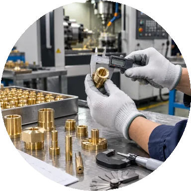
Small chips can remain in threads, cross-holes and internal passages. Edge requirements, cleaning and screening should match the accessibility and function of the feature.
Finish Allowance
Plating adds material and may change thread, bore or contact conditions. Functional surfaces, masking and final dimensions should be identified before finishing.
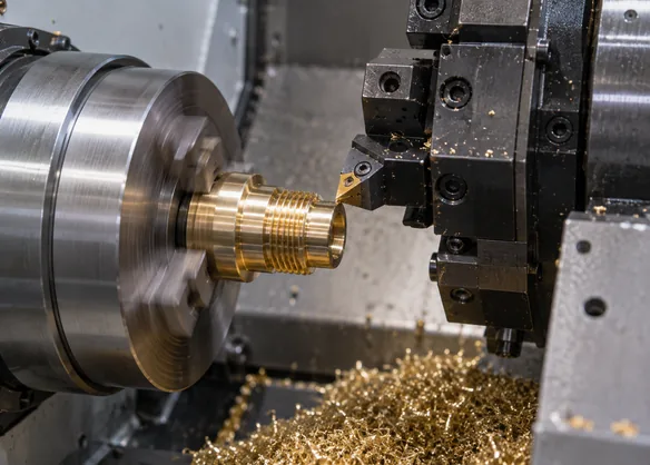
Thread inspection should reflect how the finished part mates in the real assembly.
Thread Integrity Starts with the Mating Requirement
Brass threaded inserts and knurled nuts often combine three functions: the internal thread must accept the mating fastener, the outside profile must locate correctly, and the knurl or flange must interact with the host material. A nominal thread callout alone may not describe the complete assembly condition.
For specified threaded features, GO/NO-GO thread gauges provide a direct acceptance method for functional thread engagement. Blind holes also require attention to usable thread depth, bottom clearance and retained chips. When plating is required, the drawing should clarify whether the thread is inspected before or after finishing.
- State the complete thread standard and fit requirement
- Distinguish total hole depth from usable thread depth
- Define the permitted lead-in and first-thread condition
- Identify whether the final thread will be plated
- Show the installation direction and host-material relationship for knurled inserts
Control the Relationship Between Bore, Outside Diameter and Datum
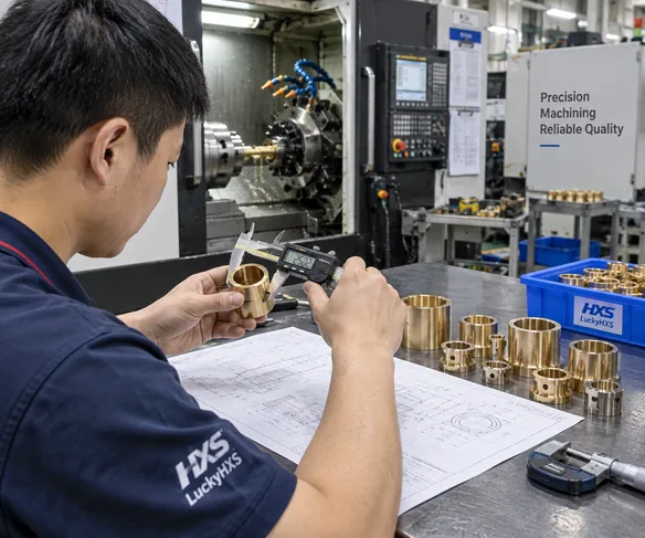
For a brass bushing or sleeve, the bore and outside diameter work as one functional system. The drawing should show which surface locates the part, which diameter controls motion or press fit, and whether concentricity, runout or straightness is the correct control for the assembly.
Press Fit
The outside diameter and host bore control retention. Wall thickness and press direction should be reviewed because installation can influence the final bore condition.
Slip Fit
Clearance must be defined around the actual mating part and operating condition, not only a nominal size.
Rotating or Guided Fit
Bore condition, alignment, surface requirement and lubricant or service environment may matter more than a very tight tolerance on a non-functional surface.
Plan Edge and Chip Control for Hidden Features
Brass chips can collect in blind threads, intersecting holes, narrow passages and recessed features. These areas may look acceptable from the outside while still affecting assembly, flow or electrical contact.
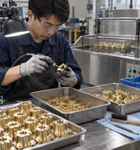
Depending on the geometry and agreed acceptance criteria, the finishing route can include mechanical deburring or grinding, ultrasonic cleaning and automatic screening. The correct combination depends on whether an edge is accessible, whether a small burr is functional or cosmetic, and whether the part contains internal features that cannot be checked from one viewing angle.
- ✓ Thread entries that must start cleanly
- ✓ Cross-holes where two drilled edges intersect
- ✓ Internal passages that can retain chips
- ✓ Thin edges that can be damaged by aggressive deburring
- ✓ Contact or sealing surfaces that must remain free of loose particles
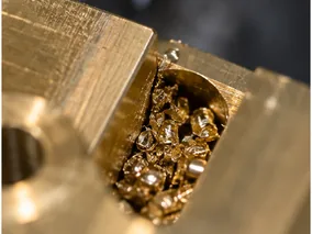
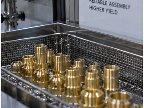
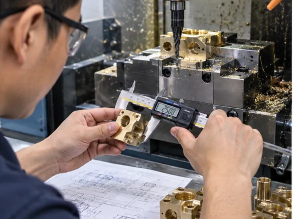
Cleaning and screening requirements should be connected to the part’s geometry and final function.
Select the Finish Without Losing Functional Fit
Surface treatment can change appearance, corrosion behavior, electrical contact and final dimensions. Define the functional surfaces before finishing is added to the routing.
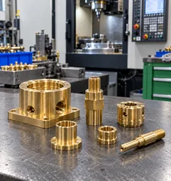
As-Machined Brass
Keeps the machined surface visible and avoids coating build-up. The drawing should still identify roughness, cosmetic zones and permitted tool marks where appearance or sealing matters.

Nickel Plating
Nickel plating can be coordinated for suitable projects. Specify the coating requirement, cosmetic expectation, contact areas, masking and whether thread or bore dimensions apply before or after plating.
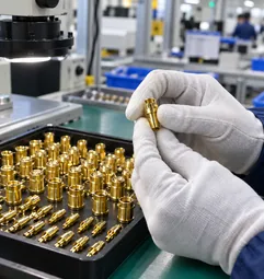
Project-Specified Gold Plating
Gold plating requires case-by-case review. State the plating type, thickness, underlayer, functional contact area, masking and acceptance criteria before feasibility is confirmed.
Do not select a finish by color alone. Review the base alloy, service environment, mating materials, electrical function and dimensional allowance as one specification.
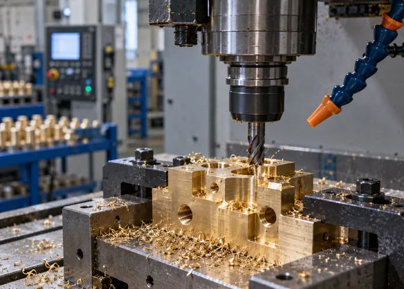
Thin Walls Change the Workholding Strategy
Thin-wall brass parts can deform during clamping, cutting, deburring or installation. The risk increases when a thin section sits close to a groove, thread, cross-hole or unsupported length.
A stable process begins by identifying where the part can be held without changing the functional bore or outside diameter. Cutting sequence, tool condition, support position and inspection state must then match the feature that matters after the part is released from the fixture.
- ■ Avoid an unnecessarily thin wall beside a deep groove or coarse thread
- ■ Show which diameter controls assembly after the part is unclamped
- ■ Distinguish free-state dimensions from installed-state requirements
- ■ Define edge conditions without requiring aggressive deburring on a fragile section
- ■ Use realistic tolerances on non-functional walls and cosmetic surfaces
When a thin wall is unavoidable, mark it clearly on the drawing and connect it to the actual assembly condition.
A Feature-Led Approach to Custom Brass Parts
The practical benefit is a clearer connection between the drawing, the machining route and the way the finished brass part will be evaluated.
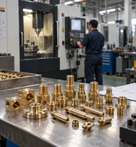
Multiple Brass Part Forms from Drawing-Based Production
LuckyHXS works with threaded inserts, bushings, pins, fittings, connectors, fluid components and milled parts. Each part is reviewed as a custom drawing rather than forced into a stock specification.
Process Selection Around Geometry
Turning, Swiss-type turning, automatic-lathe turning, milling and turn-mill processing provide different ways to manage rotational features, off-axis holes, flats, pockets and datum relationships.
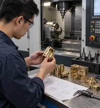
Inspection Focused on Assembly-Critical Features
Thread fit, bore and outside-diameter relationships, concentricity, edge condition and surface requirements can be identified as specific inspection priorities instead of relying on a general quality statement.

Post-Machining Control for Brass Chips and Edges
Mechanical deburring, ultrasonic cleaning and automatic screening can be included where the component geometry and acceptance criteria require them.
Control Cost by Removing Avoidable Manufacturing Complexity
Part cost is influenced by material utilization, cycle time, tooling, setup count, inspection effort and finishing. The lowest-risk cost discussion begins with the features that create those requirements.
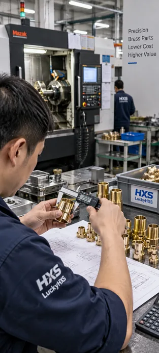
| Decision | Cost Driver | Practical Direction |
|---|---|---|
| Brass Grade | Poor chip control or unnecessary material requirements can increase machining time. | Use the exact grade required by function. Where several grades are acceptable, compare machinability and sourcing before release. |
| Tolerance | Applying the tightest tolerance to every dimension increases machining and inspection effort. | Reserve close tolerances for features that control fit, alignment, sealing or movement. |
| Setup Count | Off-axis holes, multiple faces and reversed features may require additional setups. | Use a clear datum system and review whether turn-mill processing can keep related features together. |
| Threads and Small Holes | Deep blind threads, very small holes and intersecting passages increase tool and cleaning demands. | Define usable depth, access, edge condition and inspection method explicitly. |
| Surface Finish | A general cosmetic requirement can create unnecessary rework when only one surface is visible or functional. | Mark cosmetic, contact and sealing zones separately. |
| Plating | Coating, masking and post-finish inspection add coordination steps. | Specify the finish early and identify which final dimensions apply after plating. |
A DFM review should preserve the part’s function while making non-critical requirements easier to manufacture and inspect.
How a Brass Part Moves from Drawing to Production

Drawing and Requirement Review
Confirm the drawing revision, brass grade and standard, critical dimensions, quantity, finishing requirements and the component’s assembly function.

Process and Workholding Planning
Choose turning, Swiss-type turning, automatic-lathe turning, milling or turn-mill processing according to geometry, datum relationships and tool access.
Critical-Feature Planning
Identify threads, fits, concentricity, small holes, thin walls, sealing faces and cosmetic areas that need specific process or inspection attention.
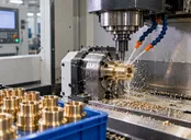
Machining and Post-Processing
Machine the required features, then apply the agreed deburring, cleaning and finishing route appropriate to the part.

Inspection and Order Review
Evaluate the specified dimensions and functional features using the agreed inspection approach before the parts proceed to the next order stage.
When a project requires sample approval, special documentation or finish validation, include those requirements in the agreed order plan rather than assuming they are standard for every part.
Inspection Built Around Functional Features
Inspection is most useful when it follows the way the part functions. A long list of measurements is less valuable than a clear plan for the dimensions and relationships that control assembly.
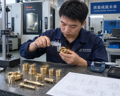
| Feature | Inspection Focus | Why It Matters |
|---|---|---|
| Internal and External Threads | Specified thread fit, usable depth, entry condition and GO/NO-GO gauge result where applicable. | Supports consistent engagement with the mating component. |
| Bushings and Sleeves | Critical ID, OD, face relationship, wall condition and drawing-defined concentricity or runout. | Supports fit, location and rotational alignment. |
| Pins and Stepped Parts | Critical diameters, shoulder locations, straightness and edge condition. | Supports insertion, positioning and movement within the assembly. |
| Small Holes and Passages | Diameter, depth, outlet condition, intersecting edges and visible retained chips. | Supports connection, flow, venting or contact requirements. |
| Surface and Finish | Drawing-defined roughness, appearance zone, contact surface and coating-related dimension. | Keeps functional and cosmetic acceptance criteria separate. |
Use the drawing to identify the inspection condition, datum and final state of each critical feature, especially when plating or installation can change the measurement.
Match the Brass Component to Its Assembly Role
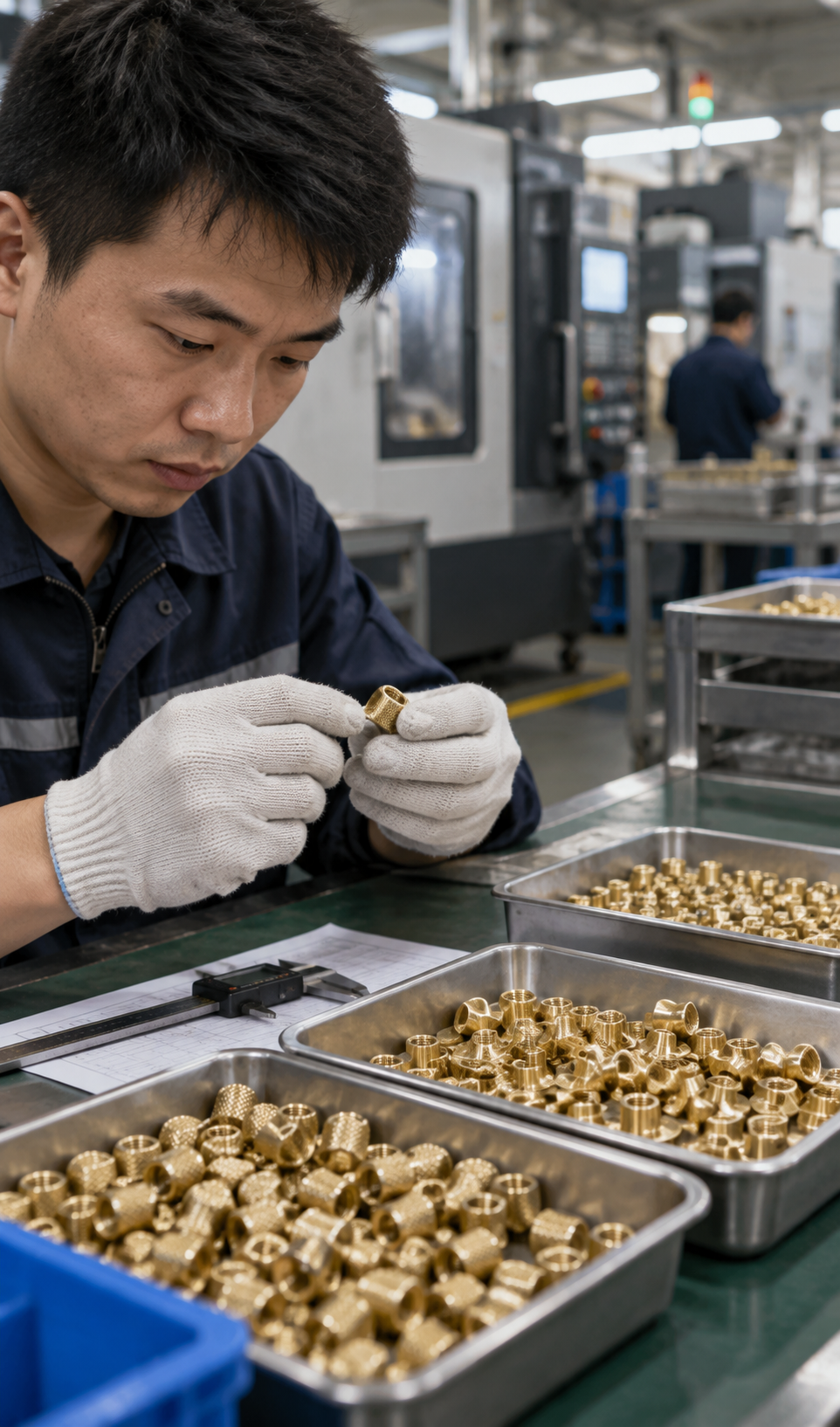


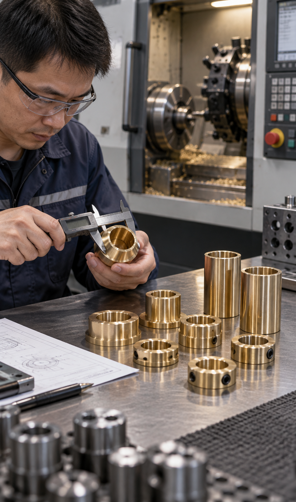
| Application Context | Typical Brass Components | Main Selection Priorities |
|---|---|---|
| Injection-Molded and Assembled Components | Threaded inserts, knurled nuts and flanged inserts. | Thread engagement, knurl geometry, installation direction, host material and flange condition. |
| Motors and Rotating Assemblies | Bushings, sleeves, spacers and locating collars. | ID-to-OD relationship, fit type, concentricity, wall thickness and surface condition. |
| Electrical and Electronic Assemblies | Contacts, terminals, connector bodies, pins and threaded connection parts. | Material specification, contact geometry, fit, thread condition and finish requirement. |
| Fluid-Control Hardware | Fittings, adapters, couplings, valve bodies and nozzles. | Thread standard, port geometry, passage cleanliness, sealing datum and service environment. |
| Instruments and Sensors | Small turned parts, sleeves, contacts and housings. | Fine-feature geometry, small holes, alignment, appearance zones and assembly relationship. |
| General Mechanical Equipment | Pins, spacers, mounting parts, blocks and custom hardware. | Datum structure, locating dimensions, load path, surface condition and mating-part compatibility. |
Threaded inserts, knurled nuts and flanged inserts.
Thread engagement, knurl geometry, installation direction, host material and flange condition.
Bushings, sleeves, spacers and locating collars.
ID-to-OD relationship, fit type, concentricity, wall thickness and surface condition.
Contacts, terminals, connector bodies, pins and threaded connection parts.
Material specification, contact geometry, fit, thread condition and finish requirement.
Fittings, adapters, couplings, valve bodies and nozzles.
Thread standard, port geometry, passage cleanliness, sealing datum and service environment.
Small turned parts, sleeves, contacts and housings.
Fine-feature geometry, small holes, alignment, appearance zones and assembly relationship.
Pins, spacers, mounting parts, blocks and custom hardware.
Datum structure, locating dimensions, load path, surface condition and mating-part compatibility.
These application examples describe common selection relationships, not automatic compliance with an industry standard. State any mandatory regulatory, material or documentation requirement in the project specification.
Is Brass the Right Material for the Part?
Material selection should follow the feature and operating requirement rather than color or material name alone.
Brass
Often selected for machinability, threaded geometry, electrical components, fittings and parts that need a clean machined appearance. Exact properties depend on the alloy and standard.

Bronze
May be considered where a grade-specific wear, bearing or corrosion requirement is more important than the machining behavior normally associated with free-machining brass. Confirm the exact bronze grade before comparison.

Pure Copper
Provides higher electrical and thermal conductivity than typical brass, but its softer and more adhesive cutting behavior can require different tooling, chip control and cycle planning.
Choose the material by comparing machinability, conductivity, wear, corrosion environment, strength, appearance, finishing compatibility and regulatory requirements. If the drawing permits more than one alloy, state which properties are negotiable and which are mandatory.
Manufacturing and Inspection in Shenzhen

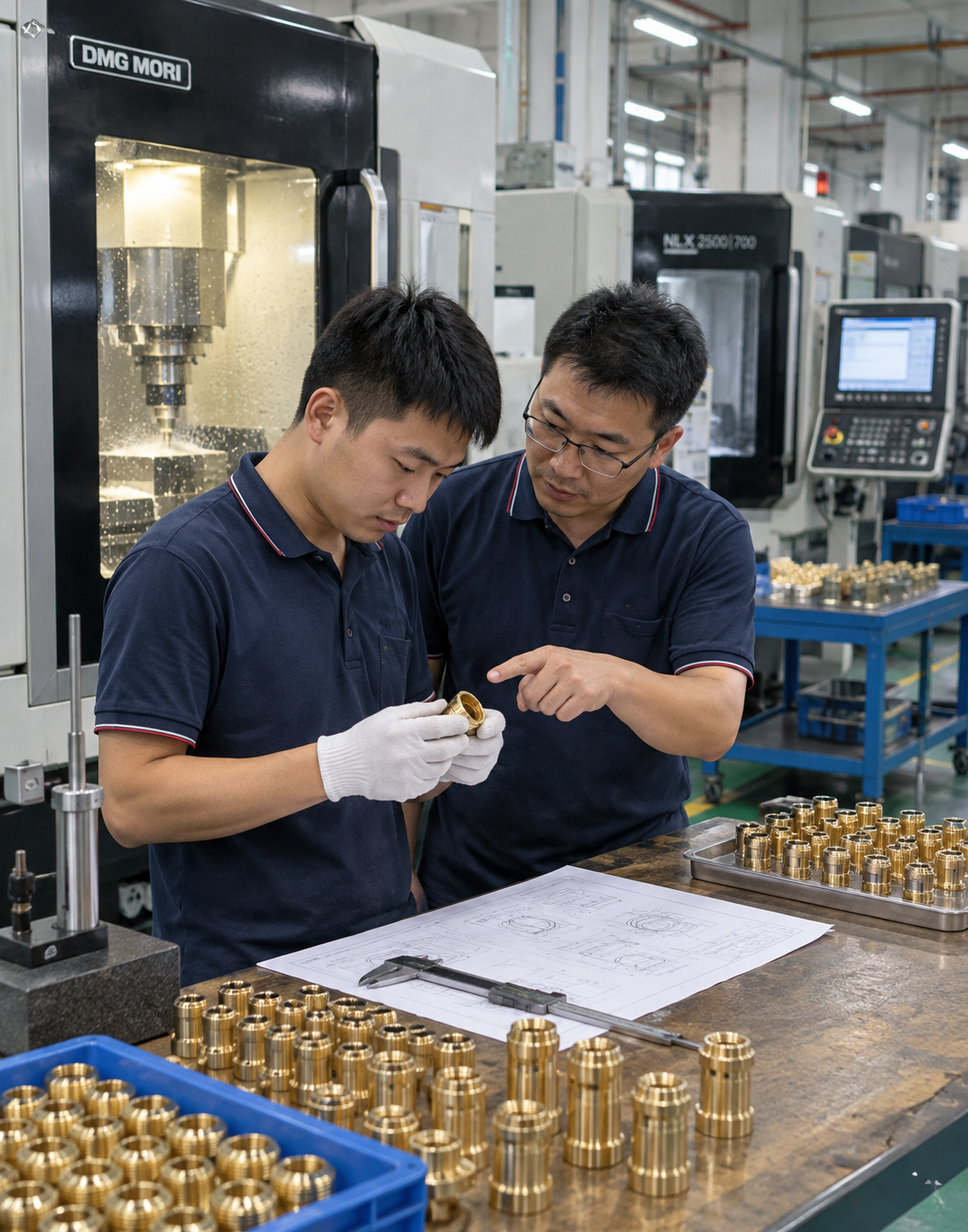
LuckyHXS produces made-to-drawing precision hardware in Shenzhen using CNC Swiss machining, CNC turning, automatic-lathe turning, CNC milling and turn-mill processing.
For brass components, process planning concentrates on the features that control assembly: thread engagement, bore and outside-diameter relationships, concentricity, small-hole condition, edge quality and finish allowance. The inspection approach is then matched to the drawing and the final state in which the part will be used.
- CNC machining of custom precision hardware
- Brass turned components with multiple diameters and threaded features
- Thread-gauge inspection for specified internal threads
- Deburring, ultrasonic cleaning and screening for suitable part geometry
- Dimensional review of bores, outside diameters and mating features
A useful supplier review should connect visible manufacturing and inspection activity to the requirements on the buyer’s drawing, not rely on unsupported capacity claims or generic quality slogans.
Brass CNC Machining Buyer Guide
Which brass grade is easier to machine?
Machinability depends on the exact alloy. H59 and C3604 are commonly considered for stable cutting and chip control, but the final grade should also match conductivity, corrosion and application requirements.
When should I choose Swiss machining?
Swiss machining is well suited to small, slender or feature-dense parts that need close support near the cutting area. Conventional turning or turn-mill may be more suitable for larger or more complex geometry.
How should plated brass threads be specified?
Define the plating type, thickness, masking requirement and whether thread dimensions apply before or after plating. Critical threads should be inspected in the finished condition.
What tolerance should I place on the drawing?
Use the tolerance required by the part’s actual function and fit. ±0.01 mm may be used as a project reference for suitable features, but tighter tolerances should only be applied where function requires them.
A complete drawing should clearly define material, critical fits, threads, surface requirements and final inspection conditions.
Continue with the Part Type or Process You Need
Use the closest product or CNC Swiss machining process page for more focused information, or discuss a drawing when the component combines several feature types.
Contact LuckyHXS
Email: admin1@lucky-hxs.com
Phone: +86 13342931453
Address: Shenzhen Bao'an Songgang
Request a Brass CNC Machining Review
Share the part type, brass grade, critical dimensions, quantity and finishing requirements that define your project. If a drawing number, revision, mating-part requirement or inspection condition is important, include it in the message so the discussion can begin from the correct specification.