
Custom Medical CNC Machining Services from a Precision Parts Manufacturer
LuckyHXS manufactures drawing-defined components for medical equipment, diagnostic instruments and precision assemblies. We review the part geometry, material, critical features, cleaning expectations and inspection requirements before selecting CNC turning, milling, Swiss machining or turn-mill processing.
- Housings, shafts, sleeves, fittings, sensor parts and custom equipment components
- Machining routes selected around geometry and functional datums
- Burr, fit, surface and documentation requirements reviewed by project
What Medical CNC Machining Means on This Page
Medical CNC machining on this page means producing custom components for medical equipment and instrument assemblies from customer drawings. LuckyHXS is a precision component manufacturer. We do not present ourselves as a complete medical device manufacturer or as the party responsible for approving the finished medical product.
Each component must be evaluated according to its own function. A housing may depend on mounting-hole position and sealing grooves. A shaft may depend on runout and bearing fit. A valve component may depend on internal edges and passage cleanliness. These requirements determine the machining and inspection plan.
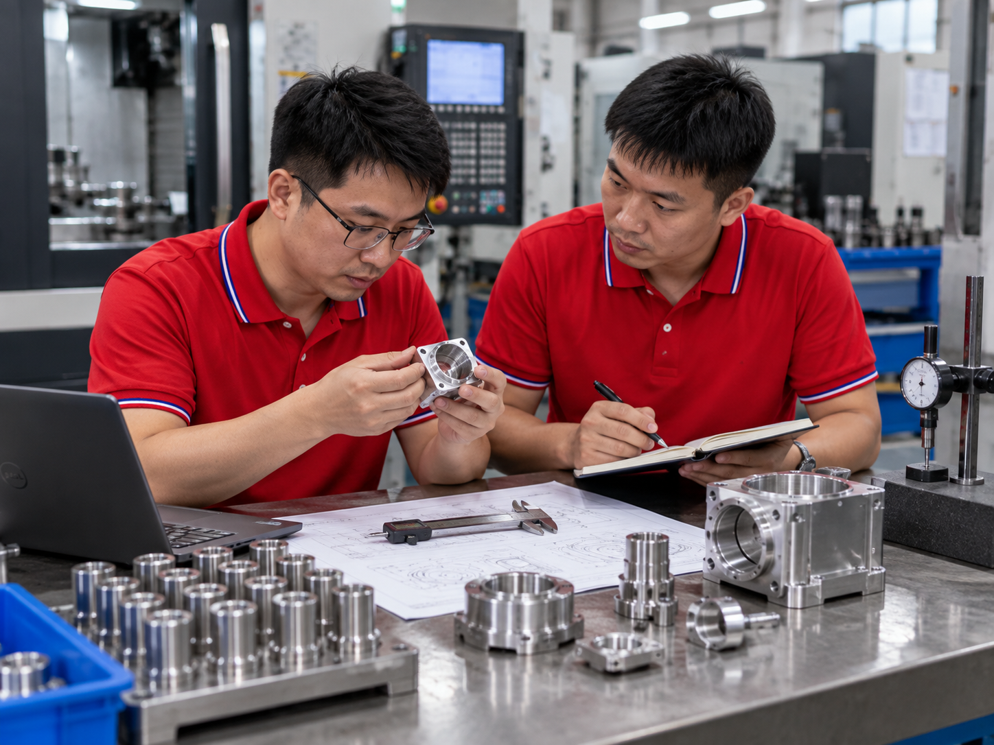
Supply Scope
Custom metal and selected engineering-plastic components made from customer drawings or samples.
Core Processes
CNC turning, CNC milling, Swiss-type machining, automatic-lathe machining and turn-mill processing.
Project Focus
Functional datums, assembly fits, threads, small holes, burr-sensitive features, surface condition and repeat-order requirements.
Approval Boundary
The customer remains responsible for the finished device classification, validation, regulatory submission and intended-use approval.
Medical Equipment Components We Review by Drawing
Choose the category closest to your component. Every part remains a custom manufacturing project, and final feasibility depends on the drawing, material, inspection method and intended equipment environment.
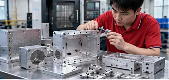
Medical Equipment Housings, Panels & Mounting Parts
Custom housings, panels, bases, brackets and locating blocks with cavities, mounting patterns, datum surfaces and drawing-defined interfaces.
Selection cues: datum structure and mounting-hole relationship.
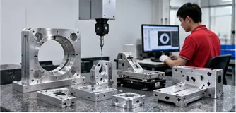
Diagnostic, Laboratory & Imaging Equipment Components
Structural and positioning components for diagnostic, laboratory and imaging assemblies, including equipment bases, optical mounts, locating parts and instrument structures.
Selection cues: positioning relationship and assembly flatness.

Medical Sensor, Probe & Monitoring Components
Probe housings, sensor mounts, small enclosures and precision interfaces with controlled bores, outside diameters, steps and mounting features.
Selection cues: sensor alignment and interface geometry.
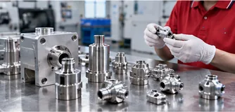
Medical Fluid-Control, Valve & Pump Components
Valve bodies, valve cores, nozzles, pump components and sleeves with internal passages, threads, sealing faces and burr-sensitive intersections.
Selection cues: passage geometry and sealing requirement.
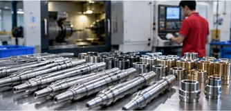
Medical Precision Shafts, Pins, Bushings & Sleeves
Rotating shafts, guide pins, locating pins, bushings and sleeves with fit-sensitive diameters, grooves, threads and common-axis relationships.
Selection cues: fit condition and runout or concentricity.
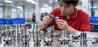
Medical Connectors, Fittings & Adapters
Drawing-defined connectors, threaded fittings and adapters with mating interfaces, internal bores, chamfers and sealing or locating features.
Selection cues: interface standard and mating fit.
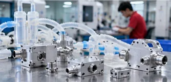
Respiratory & Ventilator Equipment Components
Custom valve blocks, flow connectors, small housings and structural components reviewed for respiratory or ventilation equipment assemblies.
Selection cues: flow-path geometry and cleanliness requirement.
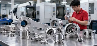
Medical Robot & Rehabilitation Equipment Components
Joint parts, bearing housings, drive shafts, motor mounting plates, brackets and locating blocks used within robotic or rehabilitation equipment structures.
Selection cues: motion relationship and mounting datum.
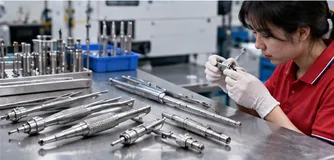
Surgical & Dental Instrument Components
Non-implant instrument handles, rotating parts, clamping components, connectors and small mechanical components reviewed from customer drawings.
Selection cues: material requirement and surface or cleaning condition.
Implantable components, patient-contact claims, biocompatibility, sterile supply and medical-device certification are not included by default. These requirements need separate qualification and documented approval before an order is accepted.
Different Component Geometry Creates Different Manufacturing Priorities
A medical equipment component may combine several functional relationships in one part. A bore may need to align with an outside diameter. A mounting pattern may need to reference a sealing face. A small passage may need a defined internal edge condition. Review these relationships together instead of treating every dimension as an isolated value.
- • Housings and mounting parts with cavities and threaded holes
- • Shafts and pins with steps, grooves and locating diameters
- • Bushings and sleeves with controlled bore-to-OD relationships
- • Connectors and fittings with threads and mating interfaces
- • Valve and pump components with small internal passages
- • Sensor mounts and probe housings with compact precision features
- • Instrument handles and mechanical clamping components
- • Brackets, bases and locating blocks for equipment assemblies
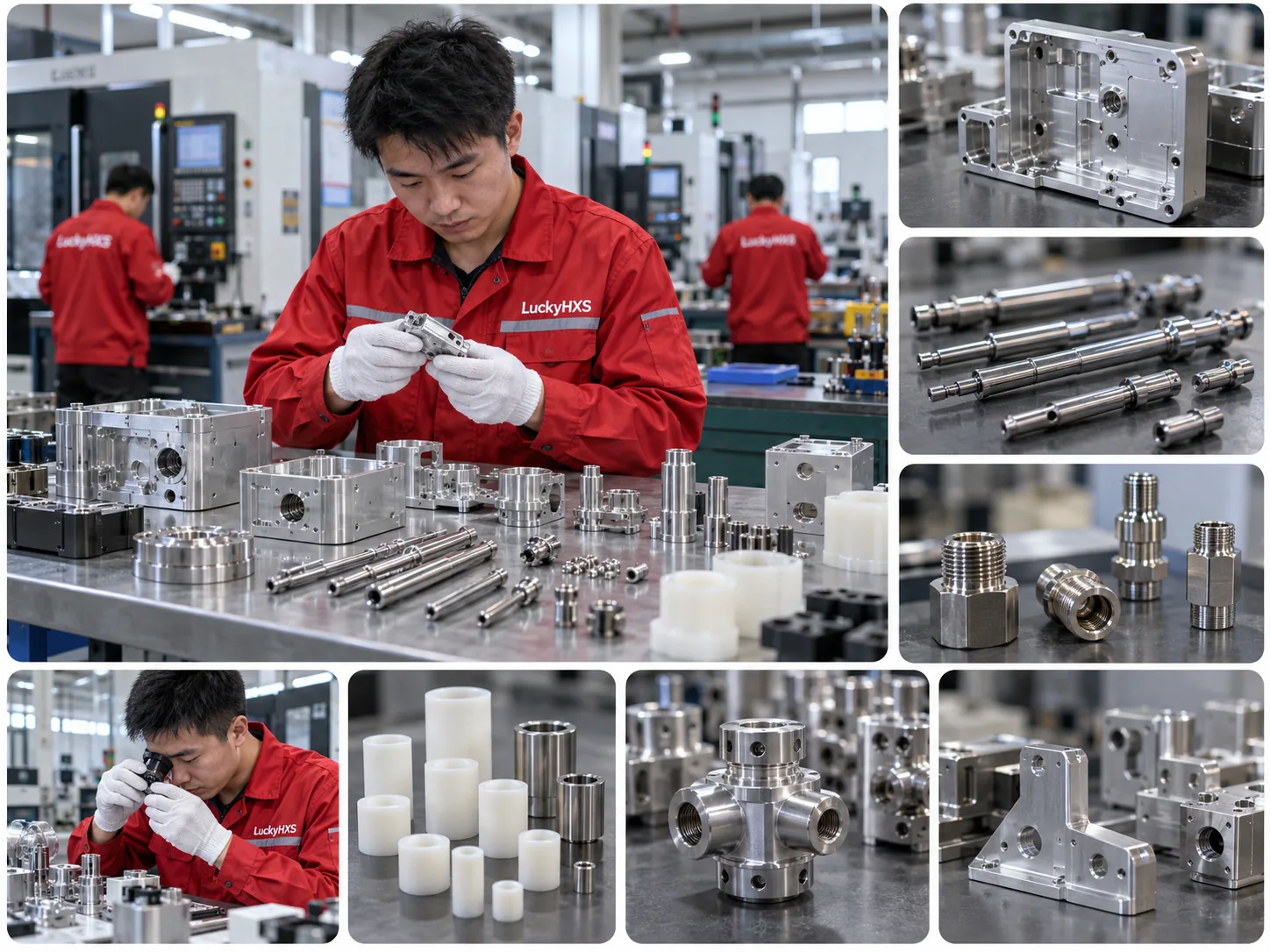
Match the CNC Process to the Component Geometry
The right process depends on the part’s primary shape, length-to-diameter ratio, secondary features, datum relationships and inspection priorities.
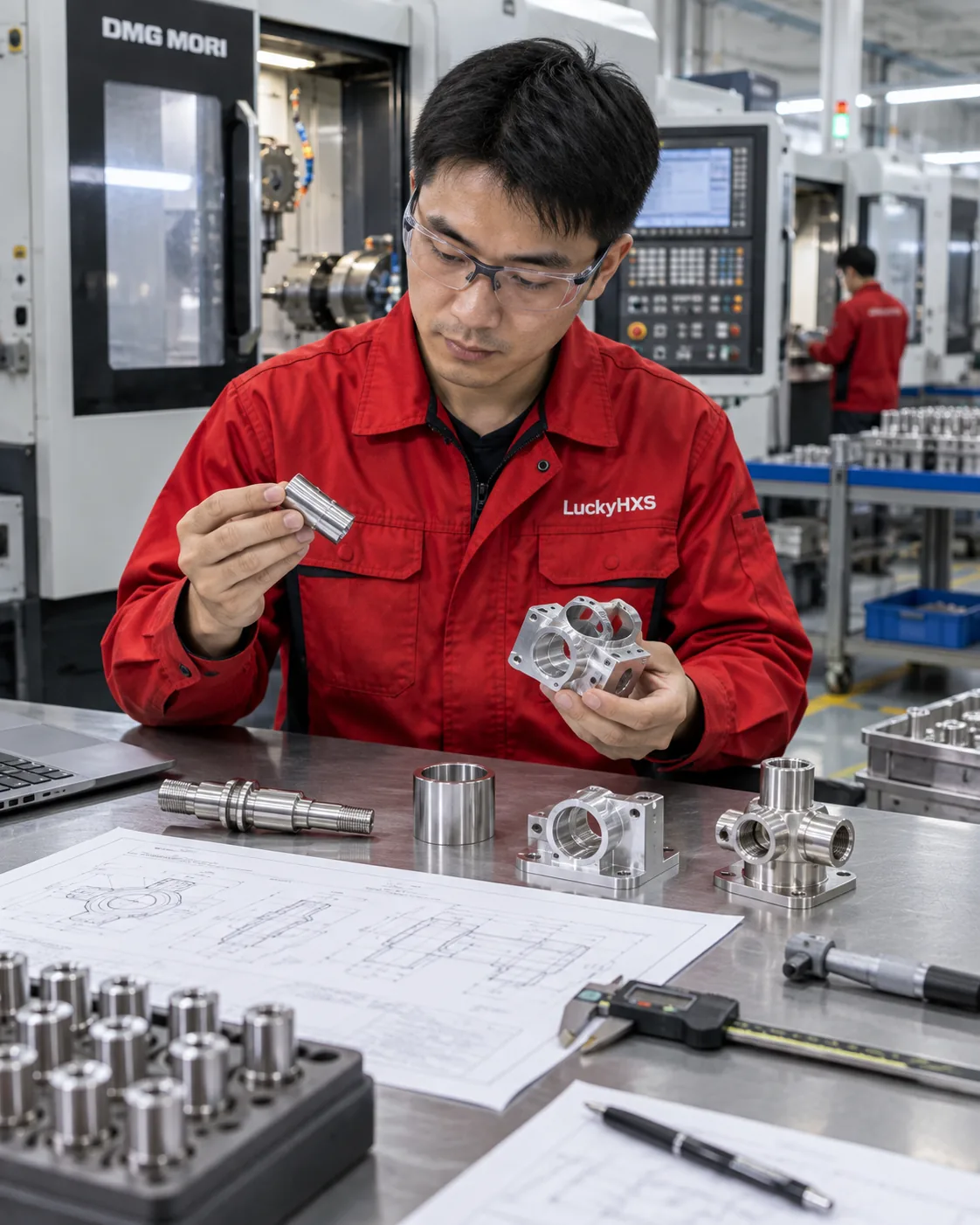
| Process | Best-Fit Geometry | Medical Equipment Component Examples | Main Review Point |
|---|---|---|---|
| CNC Turning | Rotational parts with controlled diameters, shoulders, bores, grooves and threads. | Shafts, bushings, sleeves, fittings, valve bodies and round connector parts. | Bore-to-OD relationship, runout, thread position and final surface condition. |
| Swiss-Type Machining | Small or slender components supported close to the cutting area. | Small shafts, pins, sleeves, probe bodies and compact threaded components. | Deflection, straightness, small-feature access and secondary-operation requirements. |
| Automatic-Lathe Machining | Suitable small turned parts with repeatable rotational geometry. | Nuts, sleeves, simple pins, inserts and compact turned hardware. | Tooling plan, burr control, inspection method and order quantity. |
| CNC Milling | Prismatic parts with cavities, pockets, mounting patterns, faces and multiple hole directions. | Housings, panels, brackets, bases, locating blocks and instrument structures. | Datum transfer, flatness, hole-pattern location and tool access. |
| Turn-Mill Processing | Rotational components with flats, cross-holes, slots or off-axis features. | Ported sleeves, complex connectors, valve components and multi-feature shafts. | Keeping related features within a controlled datum and reducing unnecessary transfers. |
A part should not be assigned to a process by name alone. The complete drawing determines whether one route or a combination of processes is appropriate.
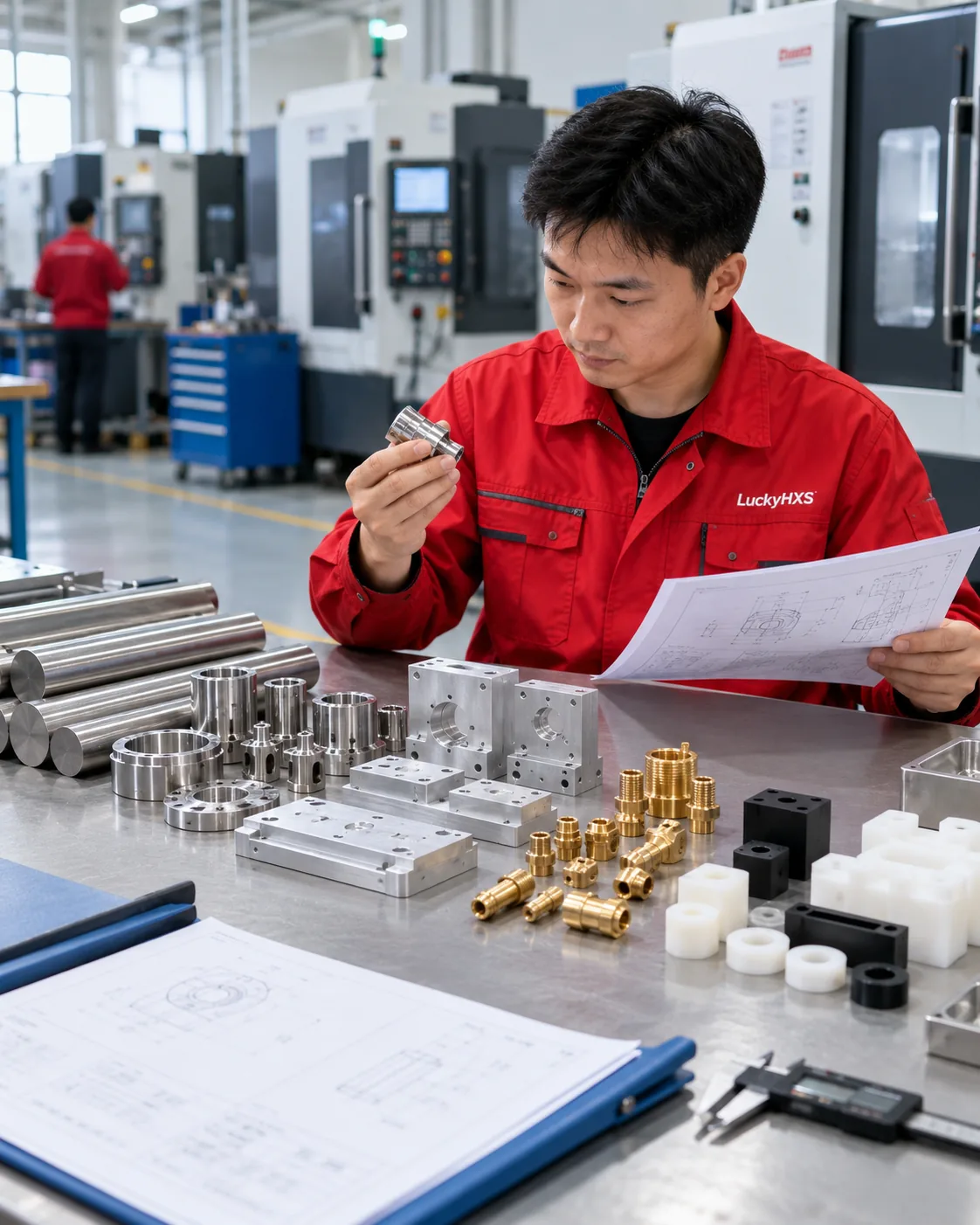
Select Material by Function, Environment and Documentation
The material must match the finished component’s mechanical function, contact environment, cleaning method, surface treatment and documentation requirements. A familiar alloy name alone does not establish suitability for a medical application.
| Recorded Material Direction | Typical Component Direction | Project Review Priorities |
|---|---|---|
| Stainless Steel 303 / 304 | Turned and milled components that require defined strength, surface condition and corrosion considerations. | Confirm the exact grade, governing standard, cleaning environment, finish, critical dimensions and required material documentation. |
| Aluminum 6061 / 6063 | Housings, panels, brackets, bases, mounts and lightweight equipment structures. | Review wall thickness, flatness, cosmetic surfaces, anodizing allowance, cleaning chemicals and mating materials. |
| Brass and Copper | Connectors, fittings, bushings, sleeves, threaded components and conductive parts where the selected alloy supports the intended function. | Confirm the exact alloy, electrical or fluid requirement, plating, corrosion environment and cleaning expectation. |
| POM and PTFE | Selected machined plastic components where low friction, electrical insulation or a specific equipment function is required. | Confirm the exact resin grade, dimensional stability, chemical exposure, temperature, cleanliness and documentation requirements. |
| Other Project-Specified Materials | Materials outside the recorded range require a separate sourcing and machining review. | Provide the full grade, standard, certification requirement, intended environment and required secondary processes before feasibility is stated. |
Material selection and final-device compliance remain the customer’s responsibility. LuckyHXS confirms only the manufacturing scope and documents agreed for the component order.
Define the Features That Control the Final Assembly
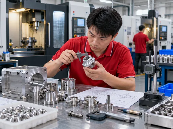
Custom medical equipment components should be reviewed around their functional relationships. Not every drawing dimension needs the same tolerance, inspection method or documentation depth.
| Feature | Drawing Definition | Why It Matters |
|---|---|---|
| Functional Datums | Primary, secondary and tertiary references for locating the part during machining and inspection. | Connects individual features to the way the component is assembled. |
| Bores and Outside Diameters | Critical ID and OD sizes, fit type, common-axis relationship and final inspection state. | Controls rotation, guidance, location, press fit and clearance. |
| Threads and Mating Interfaces | Thread standard, class or fit, usable depth, entry condition, mating component and inspection method. | Affects assembly, sealing, retention and interchangeability. |
| Mounting Holes and Patterns | Hole size, true position, counterbore, countersink and relationship to the mounting face. | Controls alignment between the machined component and surrounding equipment. |
| Small Holes and Internal Passages | Diameter, depth, intersection, outlet condition and permitted internal edge condition. | Affects tool access, burr formation, chip removal, flow and inspection visibility. |
| Thin Walls and Fine Features | Minimum wall, unsupported length, nearby slots and clamping-sensitive surfaces. | Influences deformation, workholding, cutting order and inspection condition. |
| Sealing and Contact Surfaces | Surface roughness, flatness, finish, coating and permitted edge condition. | Influences seal contact, electrical contact and assembly stability. |
| Final-Part Condition | Post-processing, coating thickness, cleaning, packaging and whether dimensions apply before or after finishing. | Prevents acceptance criteria from changing after machining is complete. |
Tolerance capability must be confirmed feature by feature. Part size, material, geometry, wall thickness, process route, datum structure, finish and inspection method all affect the final result. Do not apply one tolerance claim to every feature on the page.
Review Surface and Cleaning Requirements Before Production
A surface treatment that works for one equipment environment may be unsuitable for another. Cleaning chemicals, repeated service conditions, coating thickness and mating materials can change the correct material and finishing route.
| Requirement | Buyer Must Define | Manufacturing Impact |
|---|---|---|
| Surface Appearance | Cosmetic zones, permitted tool marks, texture and color expectation. | Determines which faces need protected handling or a defined finishing process. |
| Anodizing or Coating | Finish type, color, thickness, masking, contact areas and final-dimensional requirement. | Coating build-up can change bores, threads, fits and electrical contact surfaces. |
| Polishing or Surface Roughness | Required Ra value where applicable, measurement direction and functional area. | Influences machining allowance, finishing steps and inspection method. |
| Cleaning | Permitted cleaning agents, prohibited residues, internal passages and acceptance criteria. | Affects material selection, deburring, cleaning route and packaging discussion. |
| Sterilization Environment | Sterilization method, temperature, chemicals, cycle count and component exposure. | Requires material and finish compatibility to be defined by the device owner. Sterilization validation is not included by default. |
| Packaging | Part separation, scratch protection, labeling, cleanliness and traceability requirements. | Must be agreed before the packaging method is presented as part of the supply scope. |
Passivation, electropolishing, cleanroom handling, sterile packaging and sterilization validation must not be shown as standard LuckyHXS services without project-specific verification.
Five Risks to Resolve Before Medical Component Production
Fit and Datum Mismatch
Individual dimensions may pass while the complete component fails to align in the assembly. Connect bores, mounting holes, shoulders and sealing faces through a functional datum system.
Burrs in Hidden Features
Cross-holes, blind threads and internal passages can retain burrs or chips. Identify sensitive locations and define the permitted edge and cleanliness condition.

Material or Finish Mismatch
A familiar alloy or coating may not withstand the intended cleaning or operating environment. Confirm the full material and surface specification before production.
Prototype-to-Repeat Drift
Tool wear, setup changes, material lots and revision confusion can alter critical features in repeat orders. Define which characteristics must remain controlled after the initial approval.
Documentation Gaps
The component may meet dimensions but still fail the customer’s receiving requirements when material, inspection, revision or label records are incomplete. Agree on required documents before the order is released.
A Dimension Can Pass While the Assembly Relationship Fails
Medical equipment components often depend on feature relationships rather than one isolated size.

Housing or Mounting Part
A pocket, mounting face and hole pattern may each meet size limits while their relationship to the assembly datum remains incorrect. Position and flatness controls should follow the actual mounting method.
Shaft or Pin
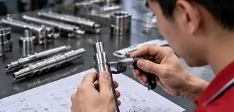
Several outside diameters may pass individual checks while runout, straightness or shoulder location prevents smooth motion or accurate positioning.
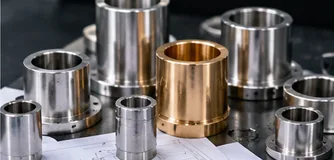
Bushing or Sleeve
The bore and outside diameter may both pass size inspection while their common-axis relationship causes uneven fit or movement.
Selection guidance:
- • Identify the feature that locates the component
- • Define the mating part and intended fit
- • Apply geometric controls to functional relationships
- • State whether inspection occurs before or after finishing
- • Avoid applying tight tolerances to non-functional surfaces without a reason
The machining and inspection plan should follow the assembled function, not only the order in which dimensions appear on the drawing.
Plan Burr and Residue Control for Hidden Features
Small holes, intersecting passages, blind threads and deep cavities can retain burrs, chips or machining residue. These areas may be difficult to inspect from one viewing direction and can affect seals, wires, moving parts or fluid paths.
The drawing should distinguish between an edge that must be broken, an edge that controls flow or sealing, and a delicate feature that could be damaged by aggressive deburring.
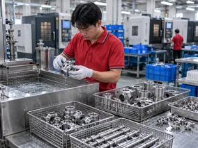
Depending on the geometry and agreed acceptance criteria, the post-machining route may include mechanical deburring or grinding, ultrasonic cleaning and automatic screening. The exact method and cleanliness requirement must be confirmed for the project.
Review priorities:
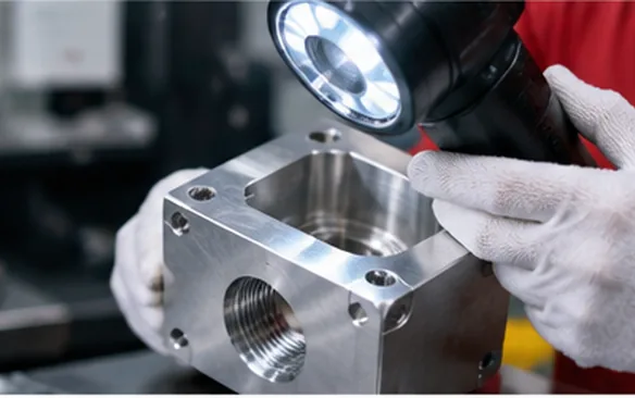
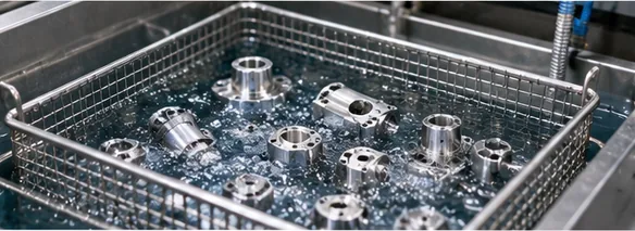
Deburring and cleaning requirements should be connected to the component geometry and receiving specification.
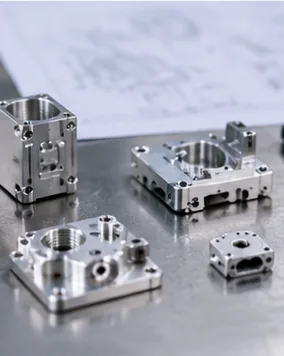
Miniature Features Change the Workholding and Inspection Plan
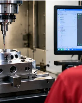
Thin walls, long slender sections, small grooves and miniature holes can move during clamping or cutting. A component may also change after it is removed from the fixture or after a secondary finish is applied.
The review should identify where the part can be supported, which feature controls final assembly and whether the specified dimension applies in a free or installed condition.
Design considerations:
- • Mark the minimum wall and unsupported length
- • Keep critical dimensions connected to a clear datum
- • Define realistic depth-to-diameter relationships for small holes
- • Identify fine edges that cannot accept aggressive deburring
- • Separate functional surface requirements from general cosmetic expectations
- • Confirm how miniature features will be inspected
- • Review coating build-up around small bores and threads
Swiss-type machining can support suitable small and slender components, but process choice still depends on the complete geometry, material and inspection requirement.
Housings Must Control Mounting, Interfaces and Internal Space Together
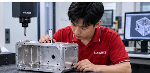
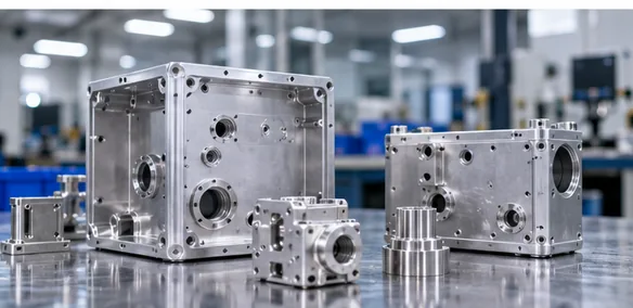
A medical equipment housing is more than an external cover. Internal cavities locate electronic, optical, sensor or mechanical elements. Mounting faces connect the component to the equipment. Holes, grooves and interfaces determine how the enclosure is assembled and protected.
Housing review priorities:
Internal Cavities
Confirm tool access, corner radii, wall thickness and the relationship between internal components and the outer structure.
Mounting Patterns
Reference hole position to the actual mounting face and identify locating holes separately from clearance holes.
Sealing Grooves
Define groove geometry, surface condition, mating seal and final dimensions after any coating.
Threaded Interfaces
State thread depth, entry condition and whether inserts or direct threads are required.
Cosmetic Surfaces
Identify only the visible or handling-sensitive areas that need a controlled appearance.
A clear housing datum system reduces ambiguity between machining, inspection and the final equipment assembly.
Define Documentation Before the Order Is Released
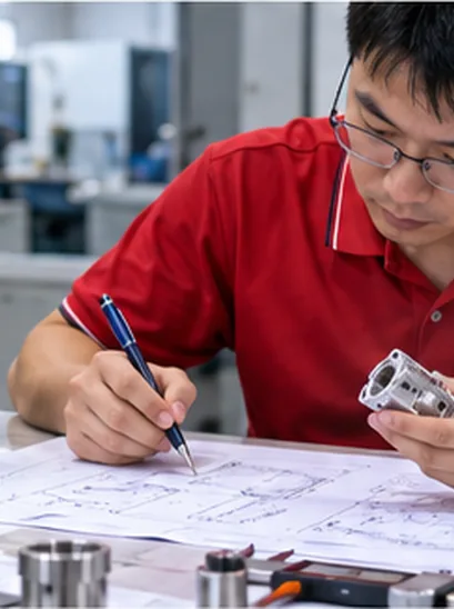
Medical equipment projects may require more documentation than a general industrial component order. The required depth should be agreed before quotation because it affects material sourcing, inspection, labeling and record handling.
| Document or Record | Purpose | Confirmation Required |
|---|---|---|
| Drawing Revision Record | Identifies the approved geometry and prevents production against an obsolete file. | Confirm the current revision, approval state and change-notification process. |
| Material Documentation | Identifies the ordered alloy, resin or material batch according to the agreed requirement. | Confirm the exact grade, standard, certificate type and traceability depth. |
| Inspection Report | Records agreed dimensions or functional characteristics. | Confirm the measured features, report format, sampling rule, units and acceptance criteria. |
| First-Article Record | Documents the initial setup or sample condition when required. | Confirm whether a first article is required and which characteristics it must cover. |
| Batch or Lot Identification | Connects delivered components to an agreed material or production record. | Confirm lot definition, label content, retention period and buyer receiving requirements. |
| Finish Documentation | Records the specified coating or secondary process when applicable. | Confirm the process specification, supplier scope and required report. |
LuckyHXS provides only the documents and traceability level agreed in writing for the project. Do not assume that a complete medical-device quality record is included with every component order.
A Drawing-Based Approach to Medical Equipment Components
Component-Level Manufacturing Scope
LuckyHXS focuses on custom machined parts for equipment and instrument assemblies. The component scope is separated from final-device approval, sterilization and regulatory responsibility.
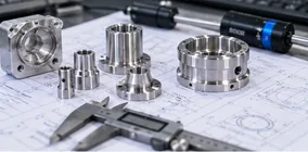
Machining Routes Matched to Geometry
Turning, milling, Swiss-type machining, automatic-lathe machining and turn-mill processing provide different routes for rotational, prismatic, miniature and multi-feature parts.
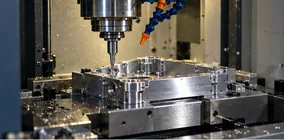
Functional Features Reviewed Early
Fits, datums, threads, small holes, sealing faces, thin walls and burr-sensitive intersections can be identified before the machining route is finalized.
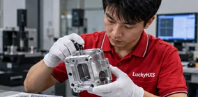
Project Requirements Defined in Writing
Material, surface treatment, inspection, documentation, traceability, cleaning and packaging requirements can be discussed as explicit project items rather than assumed after production.

This approach creates a clearer link between the drawing, the manufacturing route and the way the customer will receive and evaluate the component.
Control Cost Without Removing Functional Requirements
Custom medical component cost is affected by material sourcing, geometry, setup count, machining time, inspection, cleaning, finishing, documentation and packaging. A useful DFM review separates functional needs from avoidable complexity.
| Decision | Manufacturing Impact | Practical Direction |
|---|---|---|
| Material Grade | Special grades and documentation can affect sourcing and traceability. | Specify the exact grade and required documents. If several materials are acceptable, identify the functional limits for comparison. |
| Tolerance | Applying tight tolerances to every feature increases machining and inspection effort. | Use close tolerances on functional fits, alignment features, sealing areas and critical interfaces. |
| Datum Structure | Unclear datums create different interpretations between machining, inspection and assembly. | Reference features according to the way the component is located in the final equipment. |
| Deep or Small Features | Deep holes, blind threads and narrow passages increase tool, burr and cleaning requirements. | Define usable depth, edge condition and inspection access. |
| Setup Count | Opposing faces, off-axis holes and transferred features may increase positioning risk. | Review whether turn-mill processing or a revised datum plan can keep related features together. |
| Surface and Cleaning | Unclear cosmetic, roughness or residue requirements create avoidable finishing work. | Separate functional, cosmetic, cleaning-sensitive and non-critical surfaces. |
| Documentation | Late requests for material or inspection records can require rework or make records unavailable. | Define every required certificate, report and label before the order is released. |
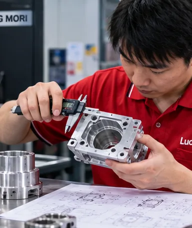
Any design change remains subject to customer approval. DFM should make the drawing clearer and more manufacturable without changing the intended function.
From Drawing Review to Repeat Production Requirements
Drawing and Revision Review
Confirm the current 2D and 3D files, material, quantity, intended component function and approval status.
Manufacturing Feasibility Review
Evaluate process choice, tool access, workholding, thin walls, deep features and secondary operations.
Inspection and Documentation Planning
Identify critical characteristics, inspection methods, sampling or full-inspection requirements and required report formats.
Initial Manufacturing Stage
Produce the agreed prototype, sample or first-article quantity when the project requires an approval stage.
Burr, Surface and Cleaning Review
Evaluate the agreed edge condition, visible residue, finish and handling requirements.
Production Release
Move into the approved production quantity only after the applicable drawing, sample and project requirements are aligned.
Repeat-Order Control
Use the approved revision and agreed critical-feature requirements as the basis for future orders. Any required lot records, retained samples or change controls must be defined by the customer and confirmed by LuckyHXS.


Prototype, sample, batch and repeat-order conditions vary by part. They must be confirmed during quotation rather than presented as one standard commercial promise.
Build the Inspection Plan Around Critical Characteristics
An inspection plan should explain which features are checked, how they are checked and what acceptance rule applies. The method must match the feature and the final state of the component.
| Feature | Inspection Focus | Buyer Decision |
|---|---|---|
| Bores and Outside Diameters | Critical size, fit, datum reference and common-axis relationship. | Identify the mating part and the fit condition that controls assembly. |
| Threads | Thread standard, fit, usable depth, entry condition and gauge requirement. | Confirm the mating thread and whether inspection occurs before or after finishing. |
| Mounting Patterns | Hole position, locating features, mounting face and datum reference. | Show which holes locate the component and which provide clearance. |
| Shafts and Pins | Runout, straightness, shoulder position, grooves and functional diameters. | Identify the rotational or locating feature that controls performance. |
| Small Holes and Passages | Diameter, depth, intersection, edge condition and visible residue. | Define the permitted internal edge and the required inspection access. |
| Sealing or Contact Surfaces | Surface roughness, flatness, finish and allowed marks. | State the mating seal, contact function and final surface condition. |
| Appearance | Cosmetic zones, permitted tool marks, coating and handling protection. | Limit cosmetic requirements to the surfaces where appearance matters. |
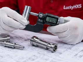
First-article, in-process and final inspection requirements can be discussed by project. The exact equipment, calibration status, report format and sampling rule must be confirmed before they are presented as order deliverables.
Match the Component to Its Equipment Function
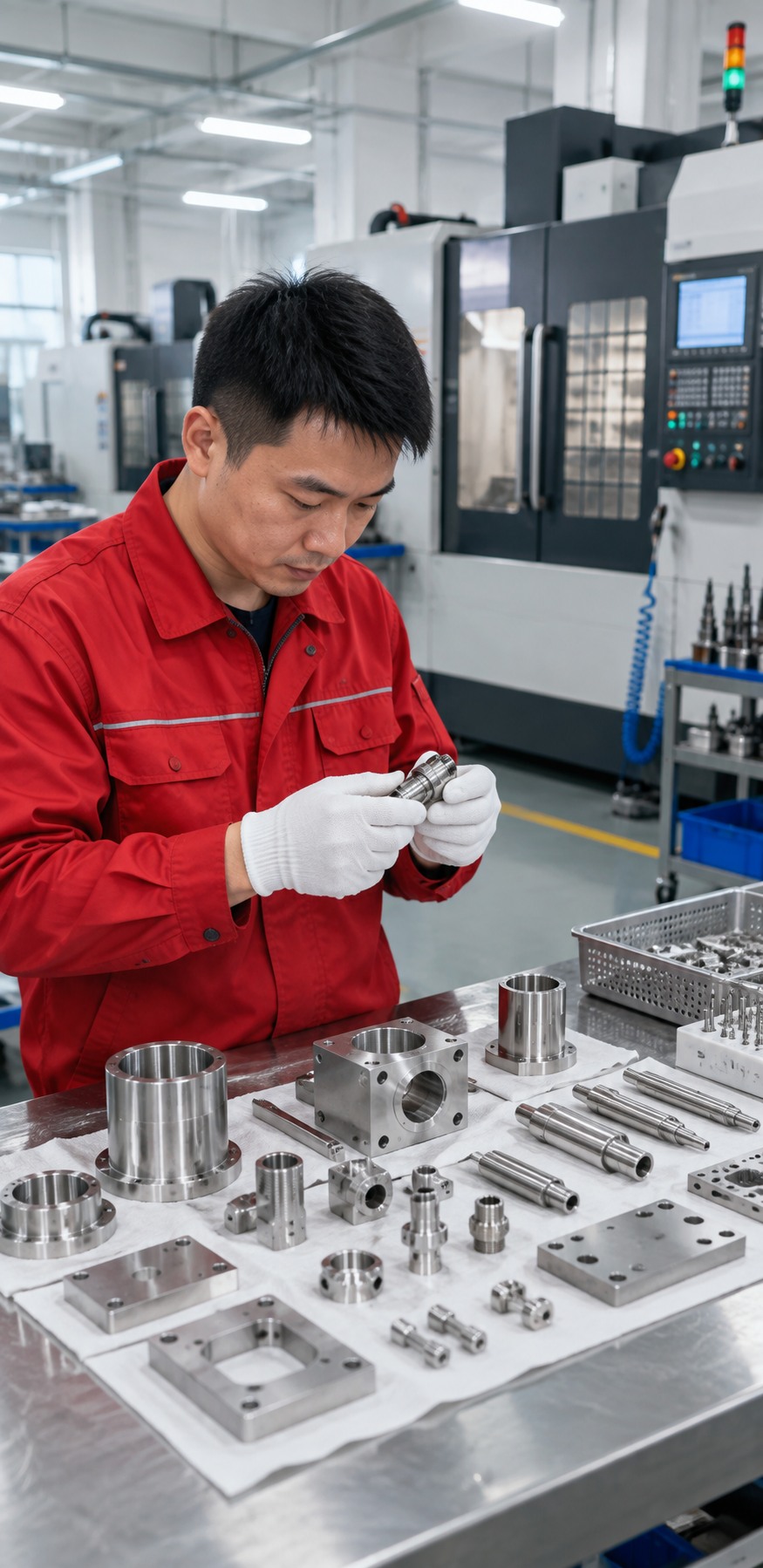
| Equipment Context | Typical Component Forms | Main Selection Priorities |
|---|---|---|
| Equipment Context Medical Equipment Assemblies | Typical Component Forms Housings, panels, brackets, mounting bases, shafts, sleeves and connectors. | Main Selection Priorities Datum structure, mounting interfaces, material, surface condition and equipment environment. |
| Equipment Context Diagnostic and Laboratory Equipment | Typical Component Forms Instrument bases, optical mounts, locating pins, probe housings and analyzer structures. | Main Selection Priorities Hole-position relationships, flatness, alignment, fine features and documentation. |
| Equipment Context Sensor and Monitoring Assemblies | Typical Component Forms Probe bodies, sensor housings, small mounts, caps and precision interfaces. | Main Selection Priorities Compact geometry, bore-to-OD relationship, cable interface, alignment and surface condition. |
| Equipment Context Fluid-Control and Pump Systems | Typical Component Forms Valve bodies, valve cores, nozzles, fittings, sleeves and pump components. | Main Selection Priorities Internal passages, sealing surfaces, small holes, threads, burrs and cleanliness. |
| Equipment Context Respiratory and Ventilation Equipment | Typical Component Forms Valve blocks, flow connectors, housings and structural components. | Main Selection Priorities Flow path, sealing interface, residue-sensitive features, material and cleaning environment. |
| Equipment Context Medical Robots and Rehabilitation Equipment | Typical Component Forms Joint parts, drive shafts, bearing housings, motor mounts, brackets and locating blocks. | Main Selection Priorities Motion geometry, bearing fit, runout, load path, mounting datum and finish. |
| Equipment Context Non-Implant Instrument Assemblies | Typical Component Forms Handles, shafts, clamping components, connectors and small mechanical parts. | Main Selection Priorities Material standard, fine geometry, surface condition, cleaning or sterilization environment and regulatory boundary. |
These examples describe possible component forms and selection relationships. They do not establish patient-contact, implant, sterile-supply or regulatory approval for a specific part.
Manufacturing and Inspection in Shenzhen
LuckyHXS produces made-to-drawing precision hardware in Shenzhen using CNC turning, CNC milling, Swiss-type m
For medical equipment components, the manufacturing discussion focuses on functional datums, fits, threads, small holes, burr-sensitive features, surface condition and the inspection records agreed for the order.
- • CNC machining of drawing-defined precision components
- • Turning of shafts, sleeves and threaded parts
- • Milling of housings, brackets and mounting components
- • Inspection of bores, outside diameters and mating features
- • Thread-gauge review for specified threaded parts
- • Deburring, cleaning and screening for suitable component geometry

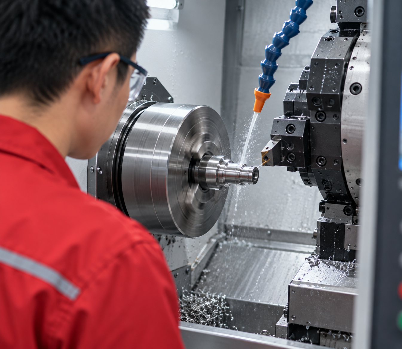


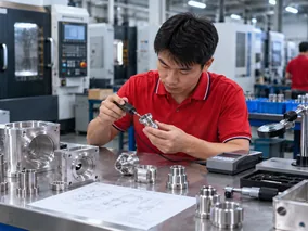
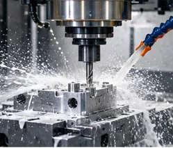
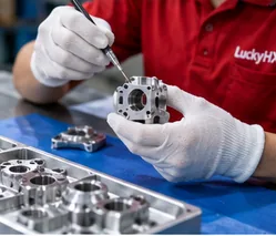
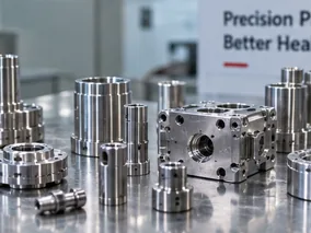
Supplier evaluation should connect real manufacturing and inspection activity to the component drawing. Medical certification, cleanroom operation, sterile packaging and regulatory approval must be verified separately and must not be inferred from workshop images.
Medical CNC Machining Buyer Guide
Review common questions about capabilities, material selection, processes and RFQ requirements for custom medical equipment components.
What does medical CNC machining cover?
Medical CNC machining converts an approved drawing or CAD model into a metal or engineering-plastic component used within medical equipment, diagnostic instruments, laboratory systems or related assemblies.
The machining supplier produces the defined component. The device owner remains responsible for system design, risk management, validation, intended use and regulatory approval. Keeping this boundary clear prevents a component-manufacturing service from being confused with complete medical-device manufacturing.
Which materials can LuckyHXS review?
The recorded material range includes stainless steel 303 and 304, aluminum 6061 and 6063, brass, copper, POM and PTFE. The exact grade, standard, finish and documentation requirements must still be confirmed for each project.
A material should not be described as medical grade from its common name alone. Cleaning agents, sterilization conditions, patient contact, corrosion environment, mechanical function and regulatory requirements may change the correct selection.
Which CNC process fits a medical equipment component?
Turning is generally suited to rotational parts such as shafts, bushings, sleeves, fittings and round valve components. Swiss-type machining can support suitable small or slender parts. Milling is used for housings, panels, brackets, bases, cavities and multi-face structures.
Turn-mill processing becomes relevant when a rotational part also contains flats, cross-holes, slots or off-axis features. The complete geometry, datum system and quantity determine the final process.
How should burr and cleanliness requirements be specified?
Identify every burr-sensitive intersection, including cross-holes, blind threads, internal passages, sealing edges and wire-contact areas. State the permitted edge condition and the inspection access.
Also define prohibited residues, cleaning chemicals, packaging expectations and whether the requirement applies to visible surfaces or internal features. Do not replace a measurable acceptance condition with a general phrase such as “clean part.”
How can repeat-order consistency be planned?
Begin with one approved drawing revision and identify the dimensions, fits, threads, surfaces and documentation that must remain controlled. If an initial sample or first article is required, define what approval covers.
For repeat orders, clarify revision control, material lots, inspection reports, sampling rules, change notification, retained samples and label requirements. These items must be written into the project plan rather than assumed.
Does LuckyHXS manufacture implantable parts?
This page does not present LuckyHXS as an implant manufacturer and does not claim implant-grade materials, biocompatibility or patient-contact approval.
Any implantable or direct patient-contact component requires separate supplier qualification, verified material and process controls, applicable quality-system evidence, validation records and regulatory review. Do not submit such a project under a general medical equipment machining assumption.
What quality and regulatory documents are included?
Documents are included only when they are confirmed in writing for the project. Possible requirements to discuss include material documentation, dimensional inspection reports, first-article records, finish documents, batch labels and agreed traceability records.
ISO 13485, FDA/QMSR status, cleanroom handling, sterile packaging, sterilization validation, passivation, electropolishing and biocompatibility must not be claimed unless current evidence confirms the exact scope.
What should be included in an RFQ?
Include the latest 2D drawing revision and 3D model when available, exact material grade and standard, quantity, critical dimensions, GD&T, threads, fits, surface finish, cleaning requirements, documentation, inspection method, packaging and target schedule.
Also identify the component’s equipment function and any surfaces that contact seals, fluids, sensors, wires or moving parts. This context helps the manufacturing review focus on the features that matter.
A complete RFQ makes the relationship between function, material, machining, inspection and documentation visible before production begins.
Continue with the Component or Process You Need
Use the closest component or process page for more detailed selection guidance. If the drawing combines several processes, submit it for a complete manufacturing review.
Request a Medical Component Machining Review
Share the drawing, material, quantity and critical requirements for the component. Include its equipment function, mating relationships, burr-sensitive features, surface condition, cleaning expectations and required documents so the project can be reviewed against the correct scope.