
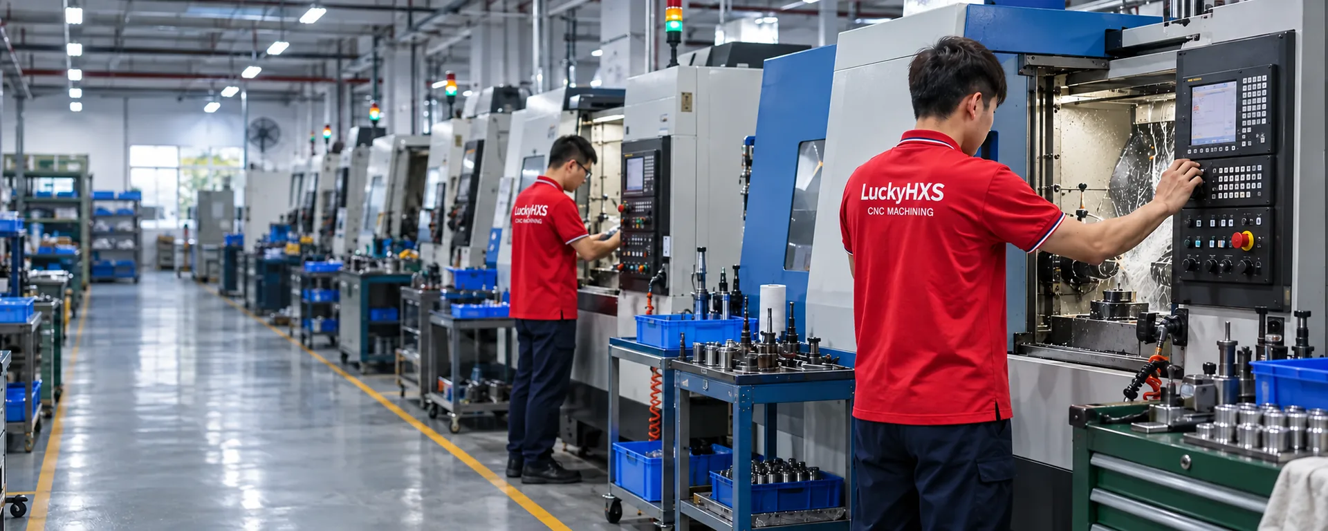
Custom CNC Turned Parts Manufacturer for Drawing-Based Production
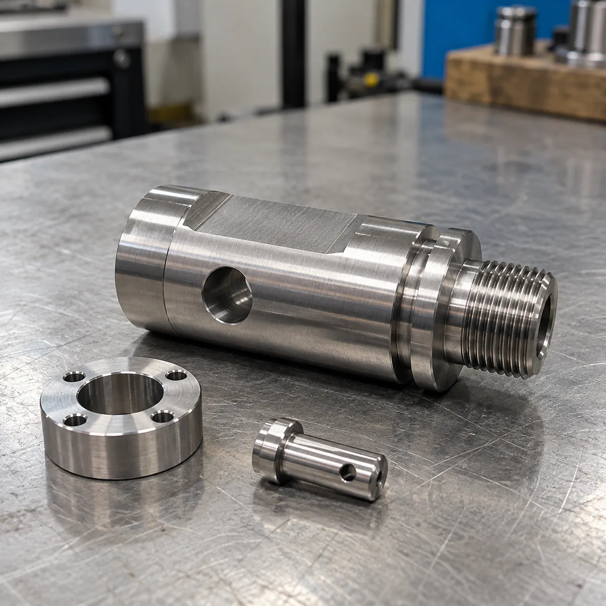
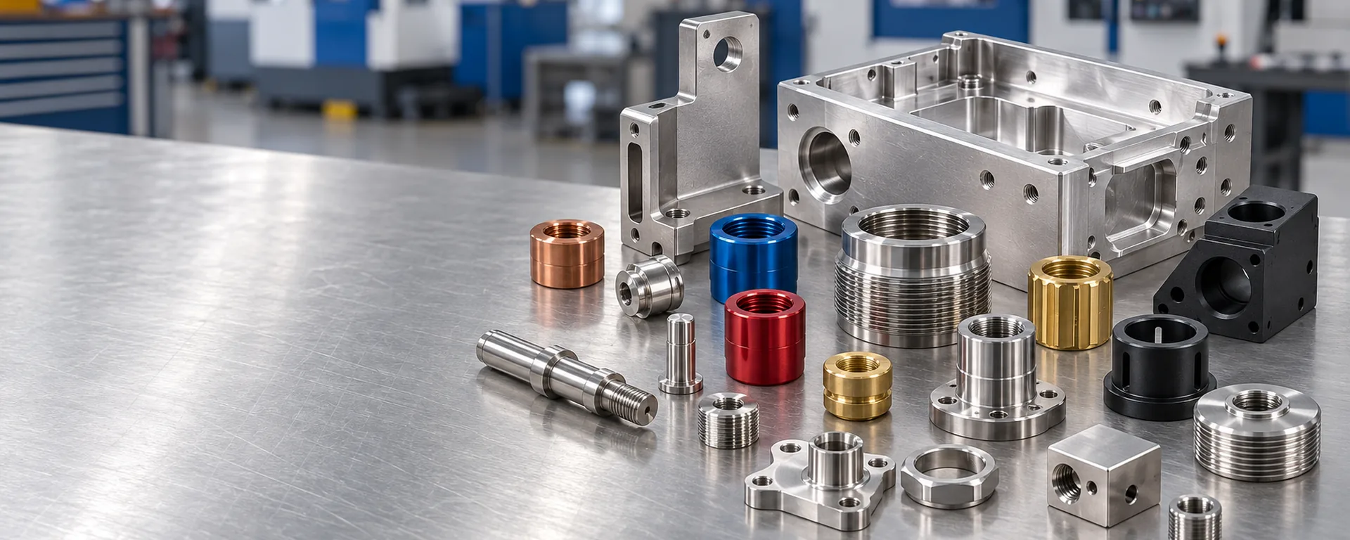
LuckyHXS manufactures custom CNC turned parts from drawings, samples, and technical requirements. We support rotational components where diameters, bores, shoulders, threads, grooves, fits, and feature relationships must work together in the final assembly.
From one custom component to repeat production, each project starts with the part geometry, material, functional requirements, finish, inspection needs, and quantity.
- Custom Parts Made to Drawings and Samples
- Metal and Engineering-Plastic Components
- Prototype Review and Repeat Production
What Makes a CNC Turned Part Custom?
A custom turned part is not defined only by its outside diameter. The drawing may require a specific bore, shoulder position, thread condition, surface finish, fit, wall thickness, sealing feature, or relationship with a mating component.
LuckyHXS reviews the part as a functional component. The goal is to align the drawing, material, machining route, finishing sequence, and inspection priorities before production begins.
Geometry
Diameters, bores, faces, shoulders, grooves, threads, chamfers, and off-axis features.
Material
Grade, condition, stock form, corrosion environment, conductivity, weight, wear, and finishing requirements.
Function
Fit, motion, sealing, fastening, positioning, electrical contact, or support within an assembly.
Acceptance
The dimensions, datums, finish condition, inspection method, and documents that determine whether the part is accepted.
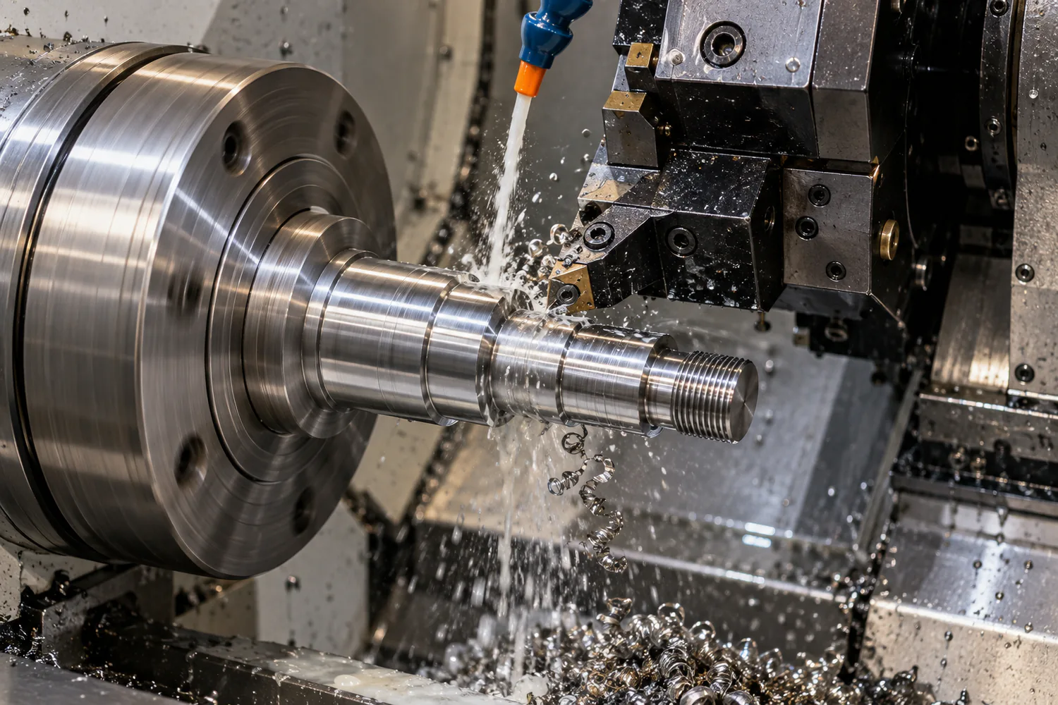
Custom CNC Turned Parts We Review
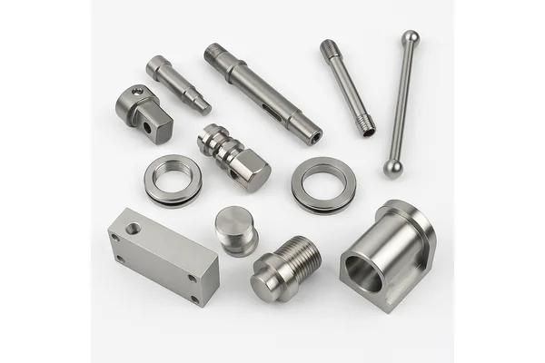
Custom Machined Shafts
Stepped shafts, motor shafts, drive shafts, locating shafts, and other round
components with controlled diameters, shoulders, grooves, threads, or mating surfaces.
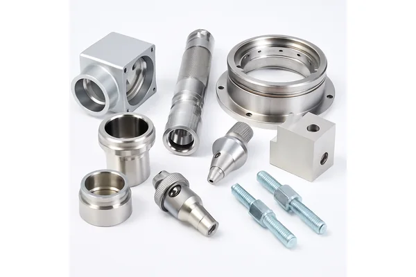
Custom Sleeves and Bushings
Sleeves, bushings, collars, and spacer components where ID, OD, wall condition, face location, and assembly fit must be considered together.
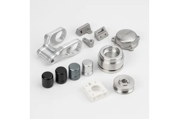
Custom Pins and Spacers
Locating pins, guide pins, contact pins, collars, spacers, and compact turned components where diameter, length, chamfer, and edge condition affect assembly.
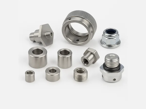
Custom Threaded Components
Threaded inserts, fittings, connectors, studs, nuts, adapters, and turned hardware with defined thread type, usable length, lead-in, relief, and burr requirements.
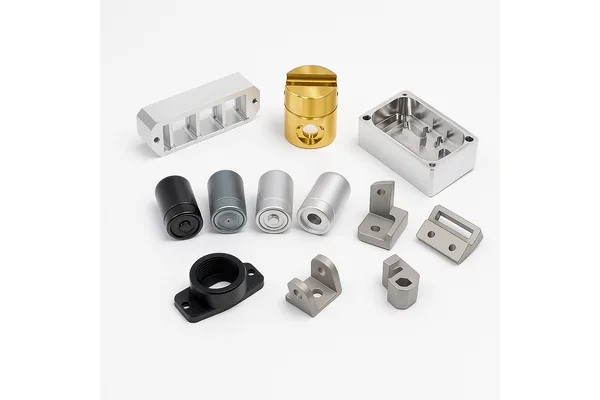
Custom Turn-Mill Parts
Rotational components that also need flats, cross holes, slots, side threads, keyways, or other secondary features.
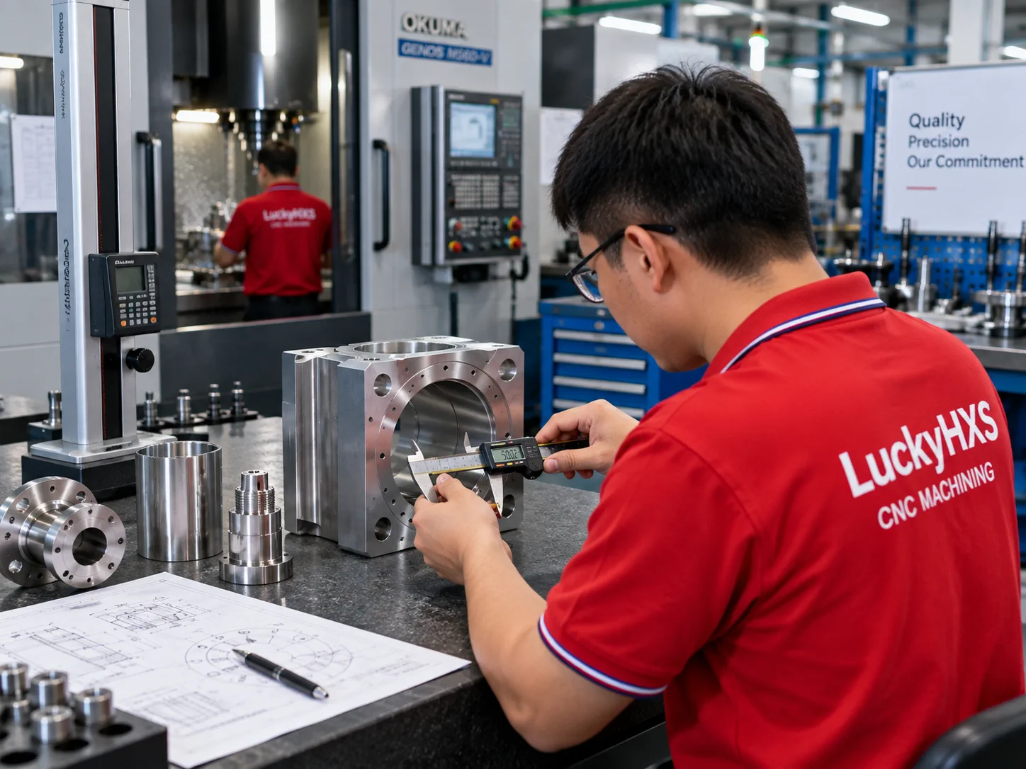
Start With the Part Geometry, Not the Part Name
A part called a “shaft,” “connector,” or “fitting” can require different machining routes depending on its dimensions, length-to-diameter ratio, material, feature access, tolerance relationships, and expected quantity.
Mainly Rotational Features
CNC turning is often a practical starting point when the part is organized around one central axis and includes OD, ID, faces, shoulders, bores, grooves, or threads.
Secondary Features
Flats, cross holes, slots, side threads, and angular features may require live tooling, turn-mill machining, or a secondary operation.
Mating Relationships
When a part works with a bearing, sleeve, seal, housing, fastener, connector, or another shaft, the functional relationship should be visible in the project review.
Custom Dimensions Need a Functional Reason
The right requirement is not always the tightest requirement. A critical feature should be controlled because it protects a fit, location, thread engagement, seal, motion, contact point, or another real assembly function.
Outside Diameter and Bore
For sleeves, bushings, shafts, and round housings, the OD and ID may need to work together with wall thickness, face position, and fit.
Shoulder and Length
Shoulders, faces, and overall length can control axial position, stack-up, seating, spacing, and assembly clearance.
Threads and Grooves
Thread designation, usable length, lead-in, relief, groove geometry, and final finish condition can affect assembly more than nominal size alone.
Runout and Feature Alignment
For rotating or mating parts, define the functional datum and the surfaces that must remain aligned during machining and inspection.
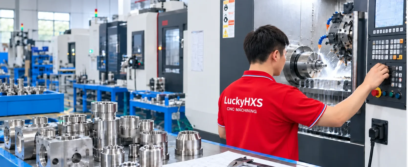
Select Material for the Part’s Function
Material selection affects machining behavior, surface condition, thread quality, deformation risk, corrosion response, conductivity, weight, finishing, and final fit. Confirm the exact grade and material condition rather than using a general label alone.
Aluminum
Consider aluminum when weight, machinability, anodizing, or component handling are relevant. Confirm alloy, temper, cosmetic surfaces, and final dimensional requirements.
Stainless Steel
Consider stainless steel where corrosion environment, strength, appearance, or surface condition matters. Confirm grade, condition, finishing route, and thread or burr requirements.
Brass, Copper, and Free-Machining Steel
These materials can be considered for conductivity, thread performance, machinability, fitting components, hardware, or repeat turning applications.
Engineering Plastics
For POM, PTFE, nylon, ABS, and related materials, consider thermal response, clamping sensitivity, moisture behavior, burr condition, and free-state measurement.
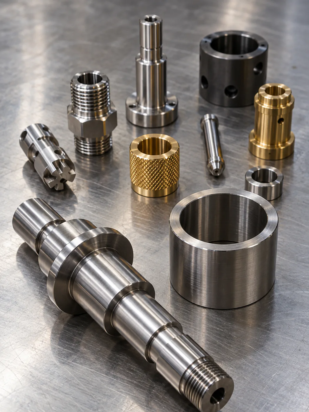
One Part Can Combine Several Manufacturing Decisions
Threaded Features
Define the thread standard, size, pitch, internal or external direction, usable length, lead-in, relief, gauge requirement, and whether the final finish affects thread fit.
Cross Holes, Flats, and Slots
Show how off-axis features relate to the main axis or a defined datum. Include the angular relationship, burr expectations, and inspection requirement where relevant.
Thin-Wall and Slender Geometry
Long shafts, narrow pins, thin-wall sleeves, and deep bores may respond differently to clamping force, support method, material condition, cutoff, and post-processing.
A Useful Custom Quote Starts With a Clear Drawing Review
A 3D model communicates nominal geometry. A controlled 2D drawing communicates tolerances, datums, threads, finishes, edge conditions, inspection requirements, and revision status. Both are useful when available.
Share These Details With Your Project
- Current 2D drawing and 3D model
- Material grade and stock condition
- Required quantity and expected order pattern
- Critical dimensions, fits, threads, grooves, or runout
- Surface finish, coating, heat treatment, or masking
- Inspection records and packaging requirements
- Notes about mating components or assembly sequence
A sample, photo, sketch, or basic dimensions can support an initial discussion when a complete drawing is not yet available.

Common Problems in Custom CNC Turning Projects
The Part Matches the Drawing but Does Not Fit the Assembly
A nominal dimension may still create an assembly problem if the mating part, tolerance direction, coating condition, surface requirement, or measurement datum is unclear.
A Thread Is Present but Assembly Is Difficult
Thread issues may come from incomplete usable length, unsuitable lead-in, relief details, coating buildup, burrs, or mismatched acceptance criteria.
A Sample Works but Repeat Orders Need Closer Alignment
Repeat production requires the approved drawing revision, material, critical features, finishing condition, and inspection expectations to remain clear.
A Thin-Wall or Slender Part Changes After Machining
Support method, clamping, cutting sequence, heat, cutoff, and free-state measurement can all affect a part that is long, narrow, or thin-walled.
Custom Turned Part Selection Guide
Use this guide to identify the points that should be clarified before quotation. Final manufacturability depends on the actual drawing, material, feature relationships, and inspection requirements.
| Part Type | Main Functional Focus | Details to Define | Review Priority |
|---|---|---|---|
| Shafts | Rotation, support, drive, location | Datum axis, diameters, shoulders, surface, runout | Alignment of rotational features |
| Sleeves and Bushings | Bore-to-OD relationship and fit | Wall condition, ID, OD, face location, free-state requirement | Fit and wall stability |
| Pins and Spacers | Position and stack-up | Diameter, length, chamfer, groove, edge condition | Mating and axial location |
| Threaded Components | Engagement and assembly | Thread callout, usable length, relief, coating condition | Final thread function |
| Turn-Mill Parts | Turning and off-axis features | Flats, holes, slots, angular relationship, burr condition | Datum transfer and setup route |
If the part combines several functions, describe the mating component and assembly sequence. This can be more useful than assigning the tightest tolerance to every dimension.
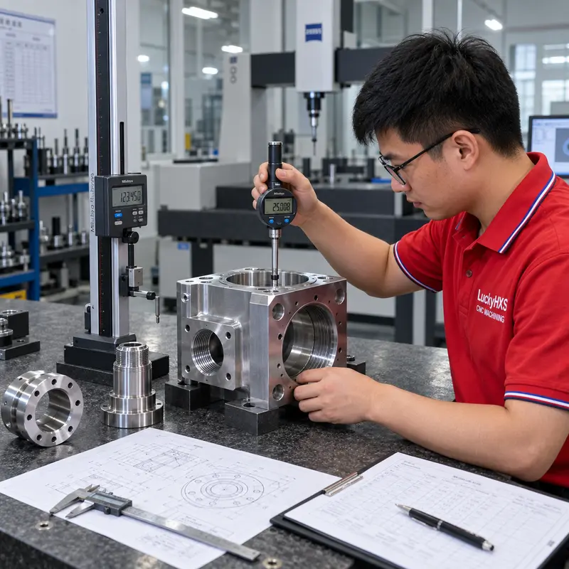
Define Precision Through Datums and Measurement Conditions
A tolerance should identify the function it protects and the datum that controls it. For rotational parts, the relationship between a bore, outside diameter, shoulder, thread, face, or sealing surface may matter more than any isolated feature.
State the Functional Datum
Show which axis, face, or feature establishes the reference for related dimensions and geometric controls.
State the Measurement Condition
Clarify whether the part is measured free-state or supported, and whether the dimension applies before or after finishing.
State the Acceptance Method
For critical features, define the requirement, datum, tolerance zone, and appropriate inspection approach instead of relying on general descriptions such as “centered” or “very low runout.”
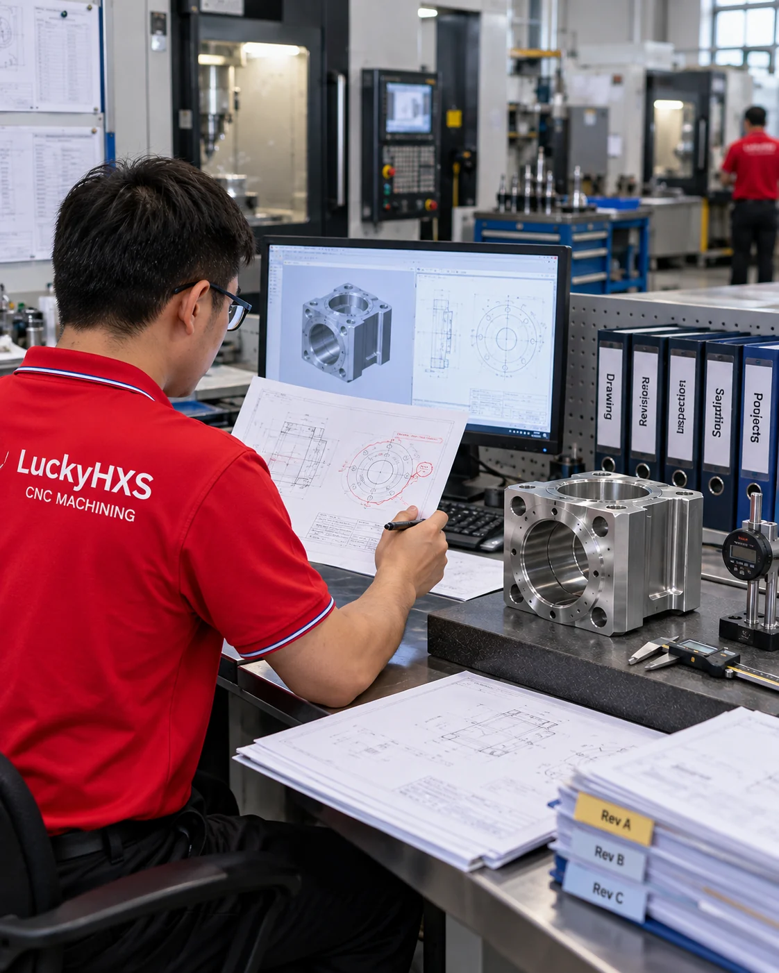
Thread, Chamfer, Groove, and Burr Details Affect Assembly
Threads and edge conditions should be specified as functional features. A component can look finished while still creating an assembly issue at a thread exit, intersecting hole, sealing edge, or mating surface.
For Threads
Specify the standard, size, pitch, class or fit, internal or external direction, usable length, entry chamfer, relief, and inspection requirement.
For Grooves and Chamfers
Define width, depth, diameter, radius, angle, and the function of the feature when it affects sealing, retention, assembly, or safety.
For Burr Control
Identify the edges that require deburring, the functional edges that must remain protected, and the intersections where hidden burrs could affect assembly or cleanliness.
Move From an Initial Part Review to Repeat Production With Clear References
Confirm the Current Files
Align the latest drawing, model, material, revision, and acceptance requirements.
Review Functional Features
Identify critical fits, threads, datums, surface requirements, and feature relationships.
Confirm the Manufacturing Route
Select the practical route for turning, secondary features, finishing, and inspection.
Approve the Reference Condition
Clarify the drawing revision, sample condition where applicable, and the inspection requirements that apply to the project.
Support Repeat-Order Consistency
Keep the approved requirements visible when the project moves from a first part to later production batches.
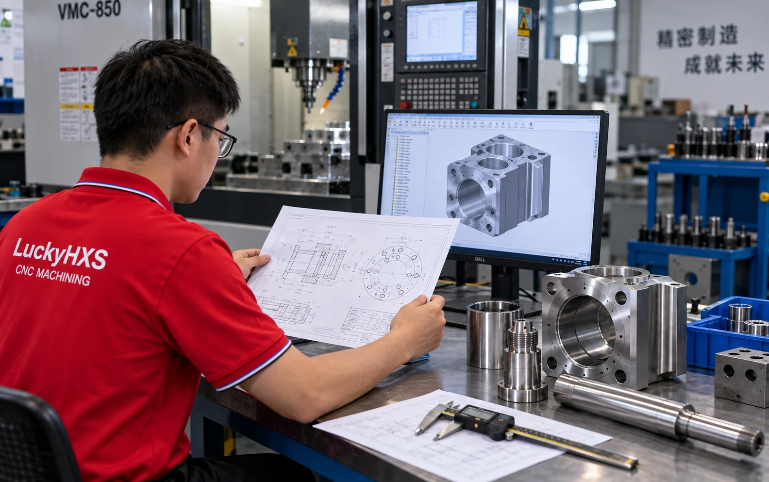
A Custom Turned-Part Project Reviewed Around Assembly Fit
Project Requirement
Use only the approved customer requirement, such as a shaft-and-sleeve fit, threaded assembly, locating feature, or rotating component relationship.
Review Focus
State only the verified review items, such as drawing revision, material condition, datum strategy, thread callout, surface requirement, or inspection point.
Practical Result
Describe only a verified non-quantified result, such as “the project requirements were clarified before production.”
Quality Review for Custom Turned Components
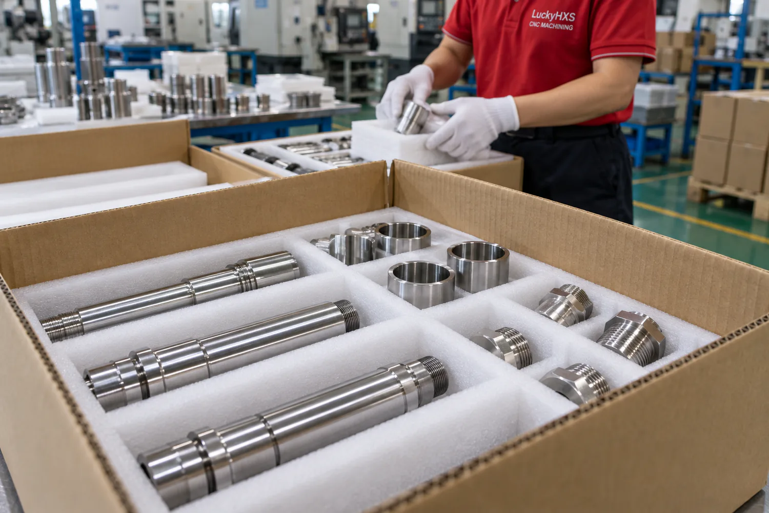
Inspection should reflect the features that make the part function. Different requirements may apply to a bearing diameter, mating bore, thread, groove, sealing surface, cosmetic face, or runout condition.
Critical Dimensions
Identify the OD, ID, length, fit, shoulder, groove, or positional features that affect assembly.
Feature-Specific Checks
Threads, burrs, surface condition, runout, and feature relationships may need different inspection methods depending on the drawing.
Project Documentation
If the project requires material confirmation, dimensional records, first-article information, or customer-specific documentation, define the requirement before production.
Confirm the Final Condition Before Surface Finishing
Deburring, polishing, plating, anodizing, passivation, black oxide, heat treatment, and cleaning can affect appearance, surface condition, thread fit, bore clearance, outside diameter, and assembly behavior.
Dimensions Before or After Finish
State whether a critical feature is accepted before or after the final process.
Protected Surfaces
Identify threads, sealing lands, contact faces, cosmetic surfaces, or mating areas that require masking, protection, or reinspection.
Final Assembly Considerations
Consider coating thickness, thread gauge condition, surface texture, burr removal, and dimensional changes where the part mates with another component.
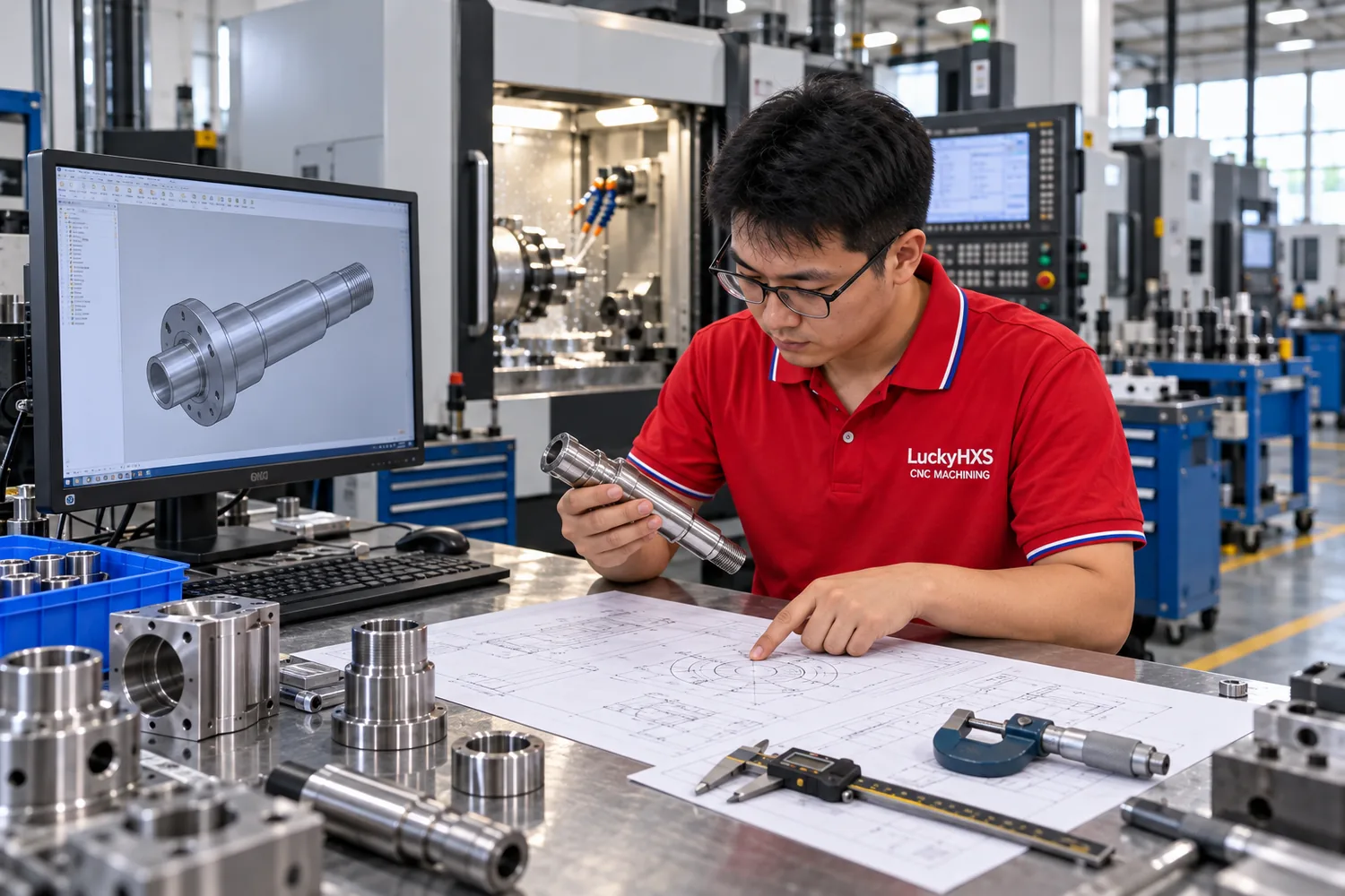
Custom Turned Components for Functional Assemblies
The same turned-part geometry can be used across different products. The application name does not replace the need to confirm the drawing, material, finishing, inspection, cleanliness, and documentation requirements for the individual project.
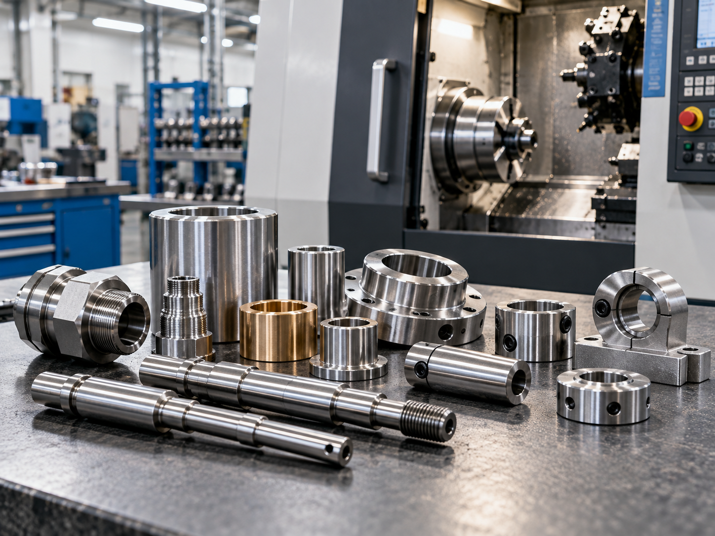
Industrial Equipment and Automation
Shafts, pins, sleeves, bushings, collars, adapters, and motion-related components.
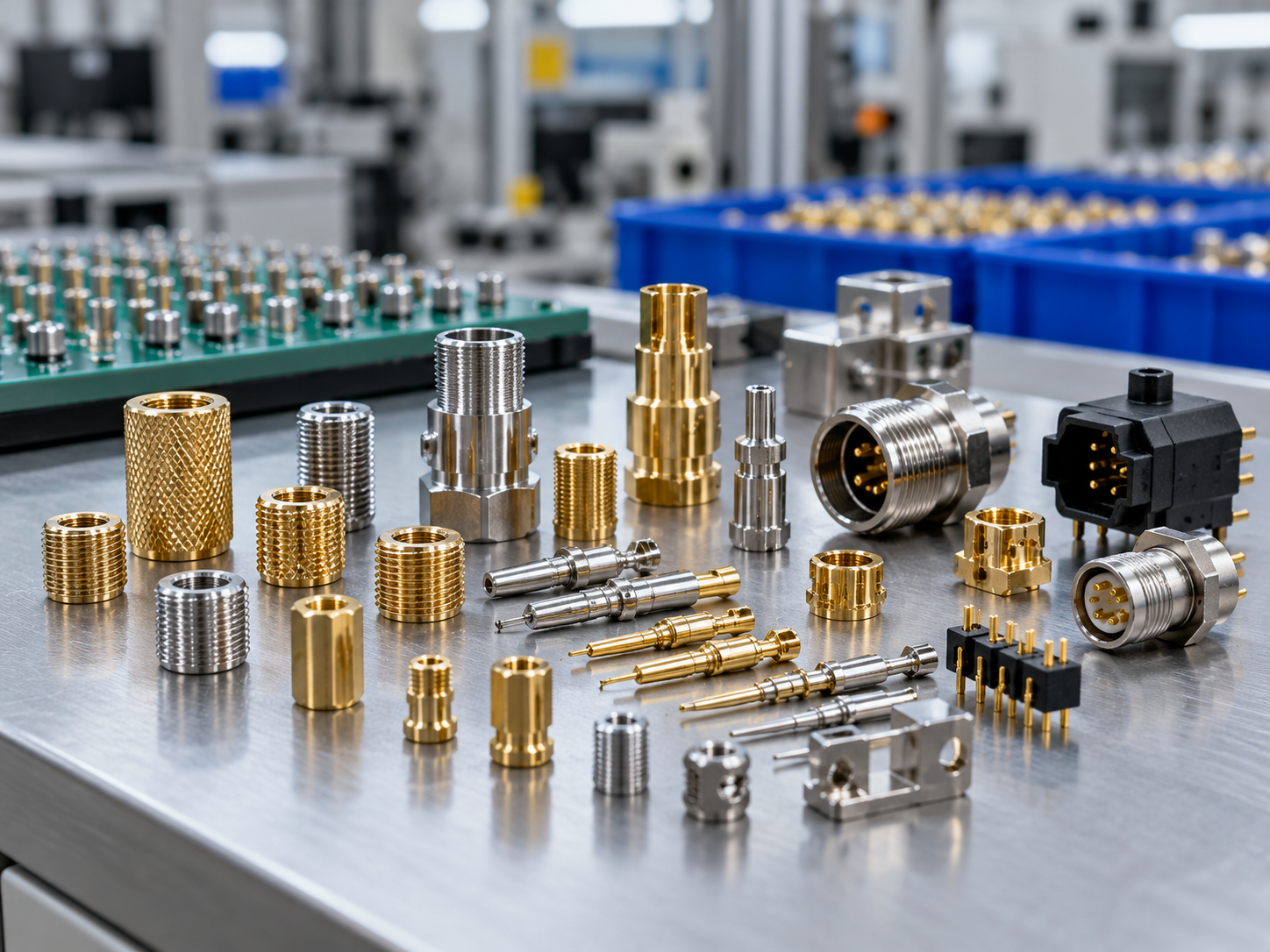
Electrical and Electronic Hardware
Threaded inserts, conductive parts, connector components, pins, and compact metal hardware.

Fluid and Mechanical Assemblies
Fittings, threaded bodies, connectors, collars, sleeves, and sealing-related rotational components.
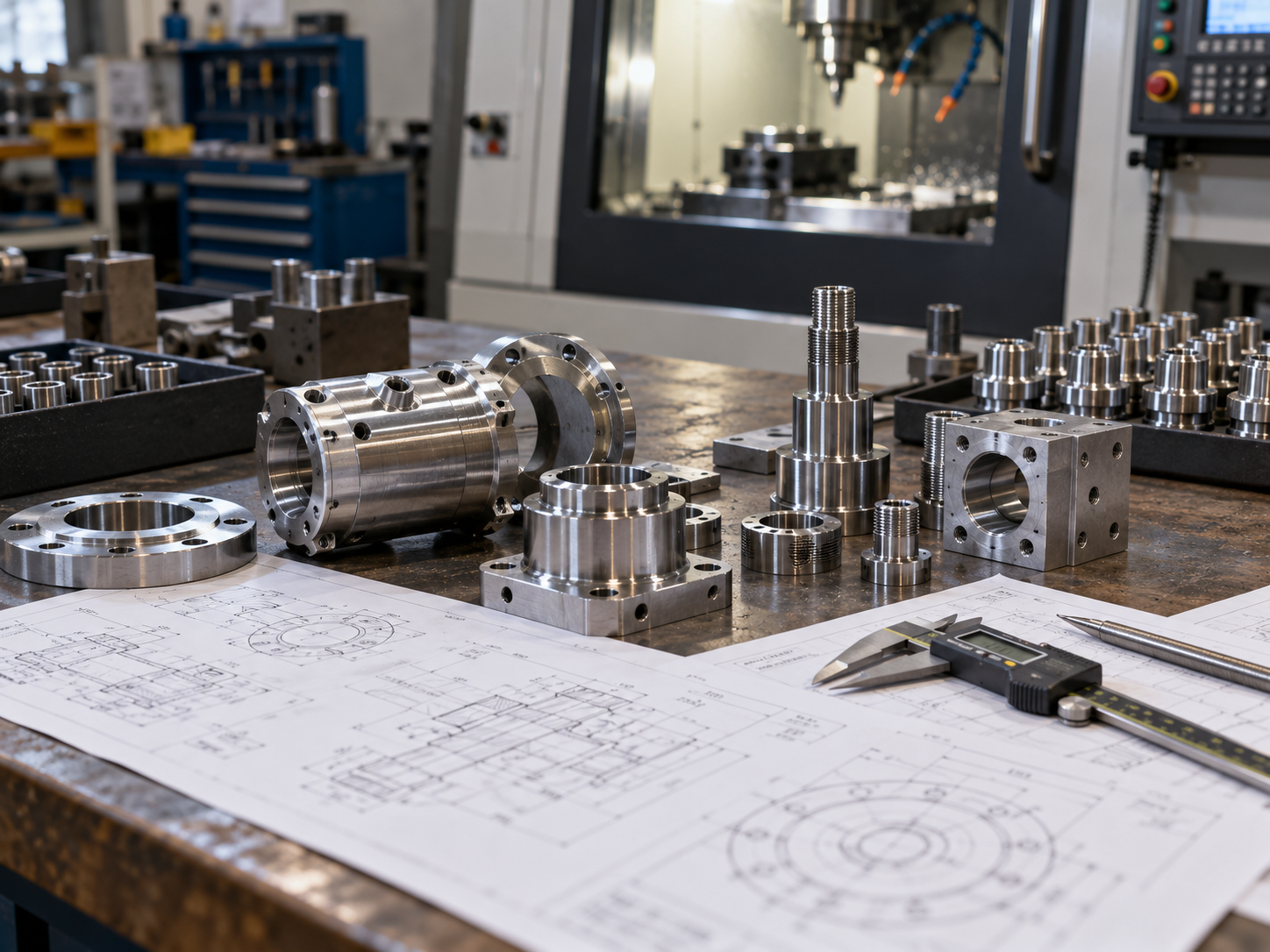
Custom Equipment Development
Drawing-based components for prototype evaluation, fit review, product updates, and repeat production planning.
What Usually Affects a Custom Turned-Part Quote?
A useful quotation reflects the complete finished part, not only the basic turning operation. Material, stock form, geometry, tolerances, secondary features, finish, inspection, quantity, and packaging can all affect the manufacturing route.
A drawing review can help identify which requirements are function-critical and which details can be clarified before production.
- Material grade and raw-stock condition
- Part diameter, length, and wall thickness
- Critical tolerance and functional relationships
- Threads, grooves, holes, flats, and secondary features
- Surface finishing, cleaning, or heat treatment
- Quantity, inspection scope, and packaging needs

Custom Manufacturing Discussions With LuckyHXS
Drawing-Based Manufacturing
Review custom turned parts from drawings, samples, material details, quantity, and technical requirements.
Process Route Evaluation
Discuss whether the part is best suited to CNC turning, Swiss-type machining, turn-mill machining, or a secondary operation.
Material and Finish Coordination
Align material grade, stock condition, finishing route, protected features, and final dimensional condition.
Project Communication for Repeat Orders
Keep critical drawing revisions, inspection expectations, and approved requirements visible as a project develops.
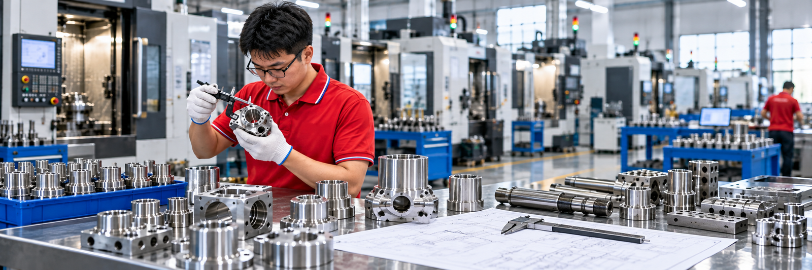
Built Around Drawings, Parts, and Production Details
Custom CNC turned parts require clear communication between the drawing, the material, the machining sequence, the inspection requirement, and the final assembly condition.
LuckyHXS supports custom metal and engineering-plastic components for projects that need a clear path from initial review to repeat manufacturing.
Custom CNC Turned Parts FAQ
What are custom CNC turned parts?
Can custom turned parts include cross holes, flats, slots, or side threads?
What files should I provide for a custom turned-parts quote?
How should I specify a tolerance for a custom turned part?
Can a sample be reviewed if a complete drawing is not available?
How do surface finishes affect custom turned components?
Explore Related CNC Machining Capabilities
Discuss Your Custom CNC Turned Parts Project
Share your drawing, model, sample details, material, quantity, and critical requirements. LuckyHXS can review the part geometry, machining route, feature relationships, finishing, and inspection priorities for your project.