Custom CNC Milling Manufacturing Service for Precision Parts
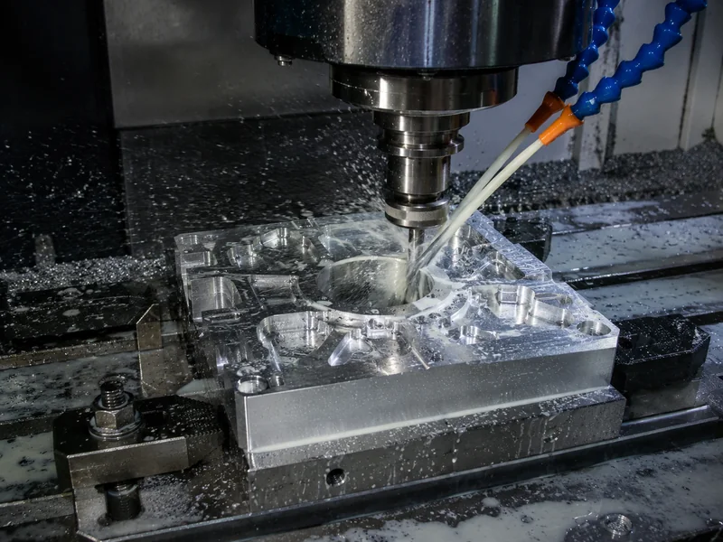
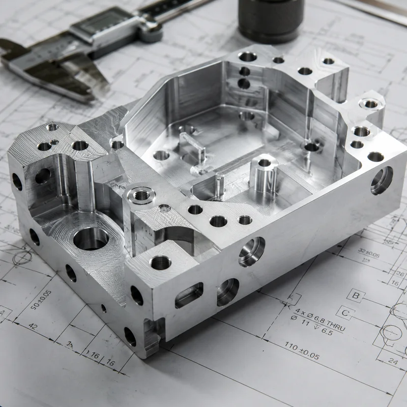
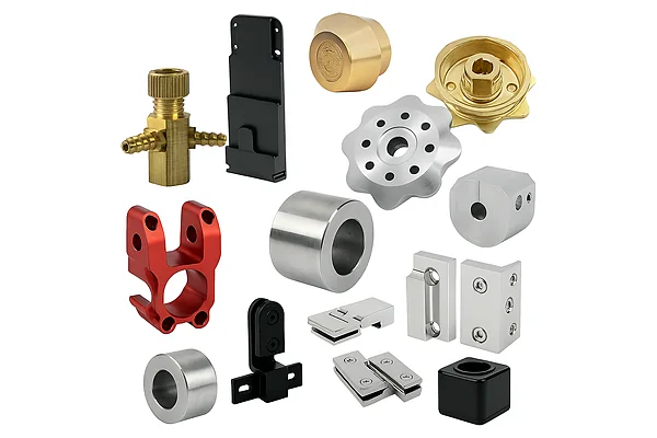
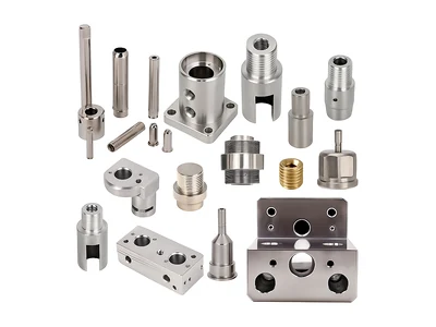
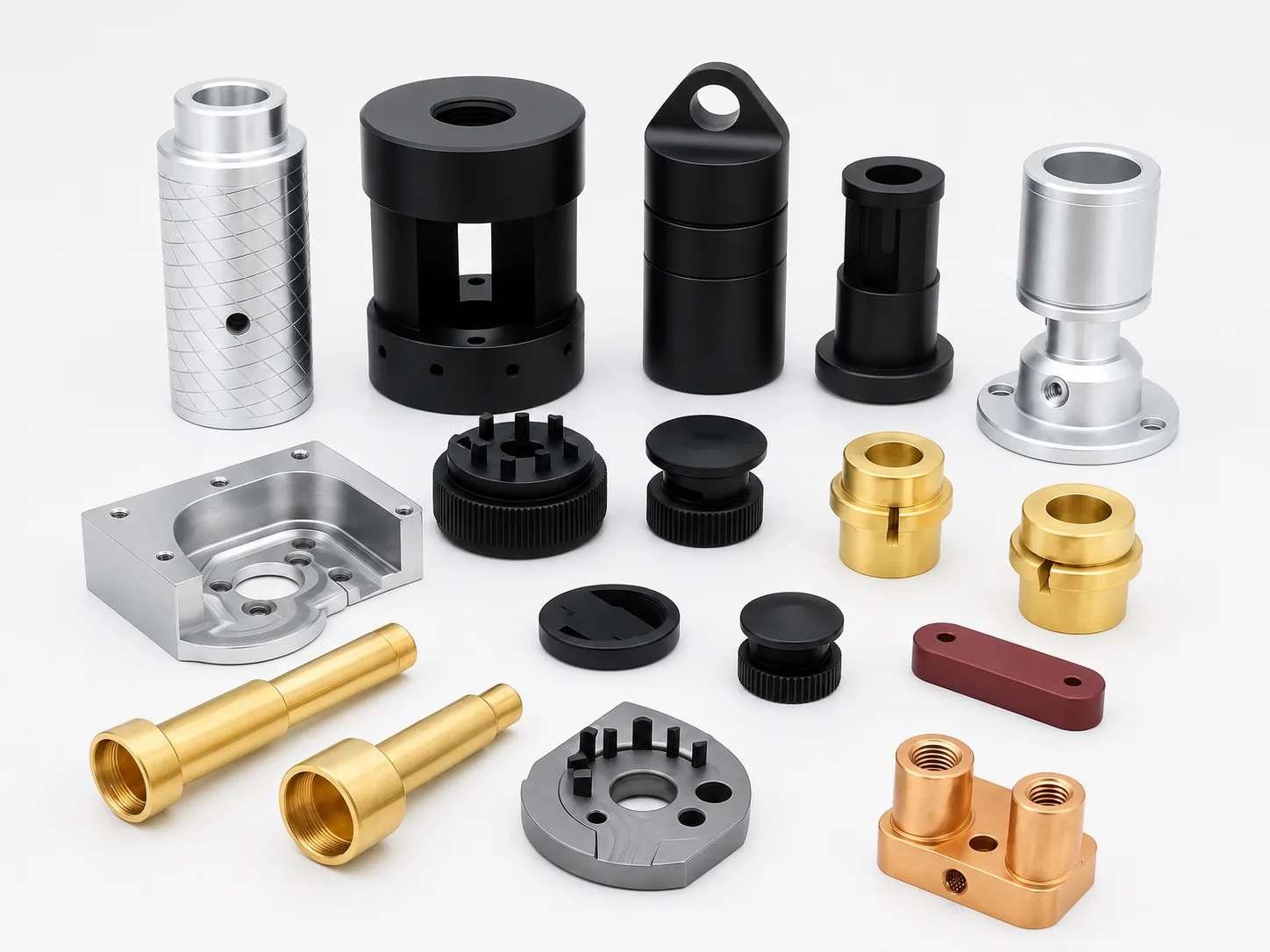
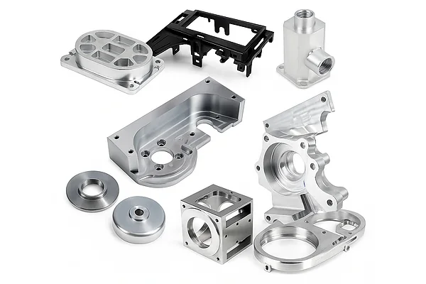
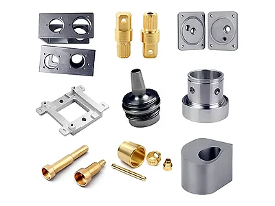
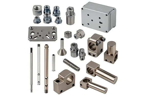
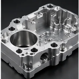
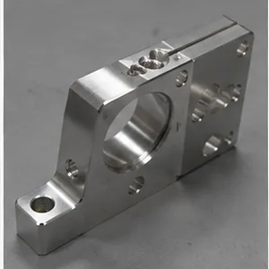
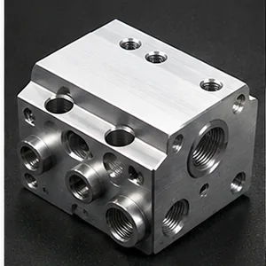
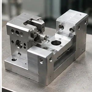
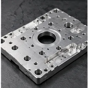
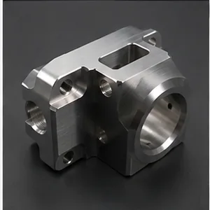
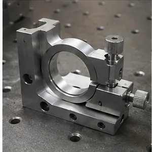
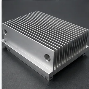
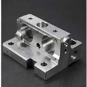
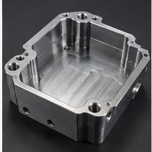
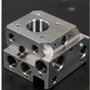
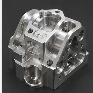
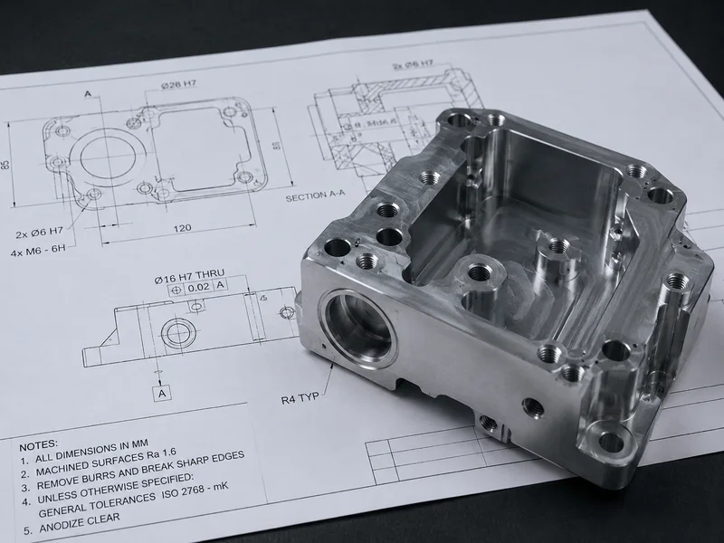
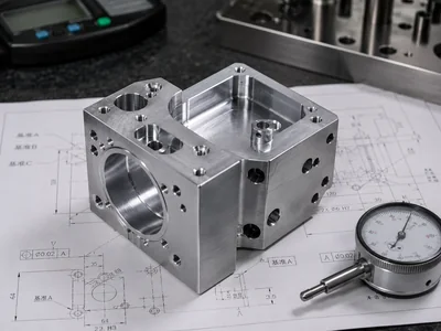
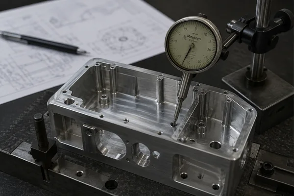
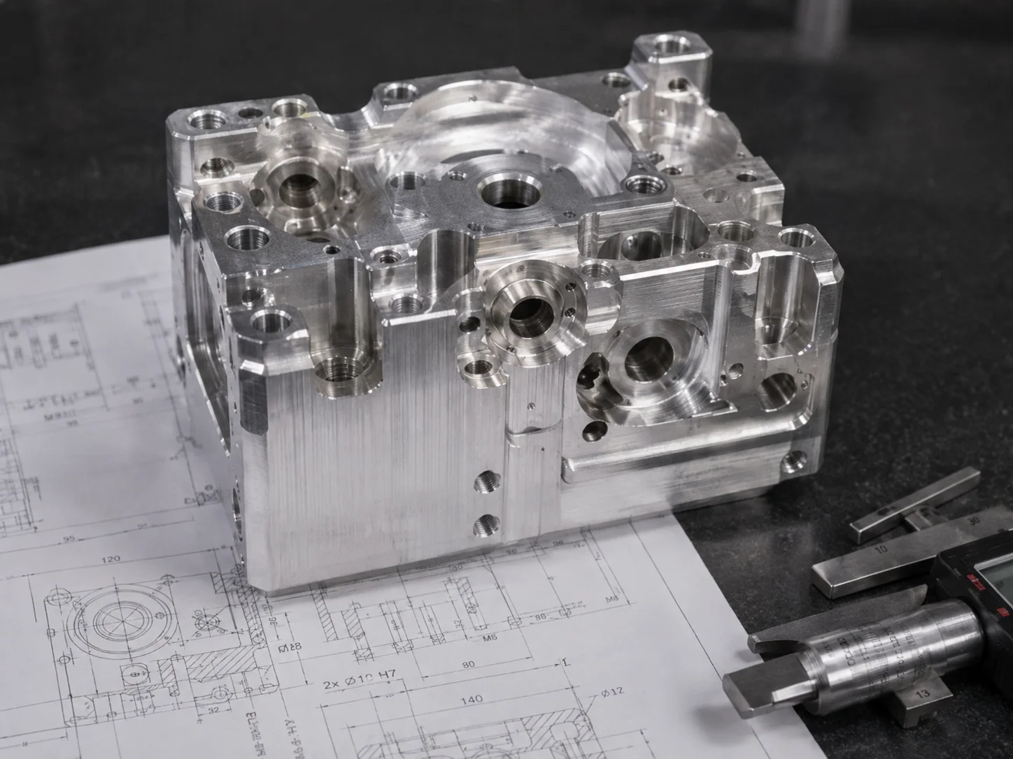
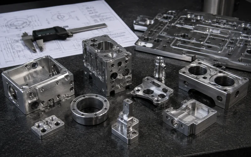
LuckyHxs offers CNC milling services for precision parts like housings, brackets, plates, and sensor components. From prototypes to production, we ensure critical features like datums, hole positions, and mounting faces align for assembly.
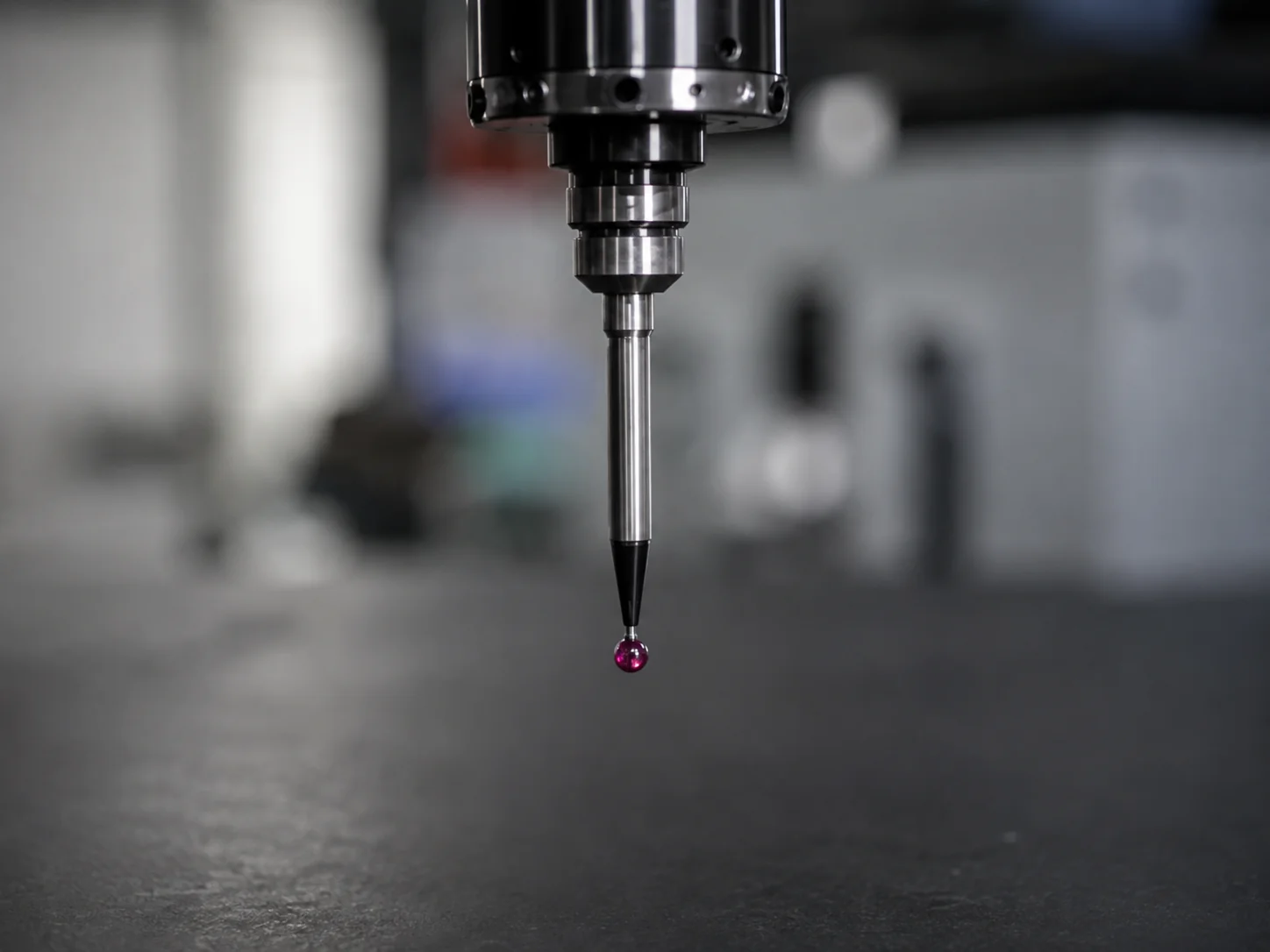
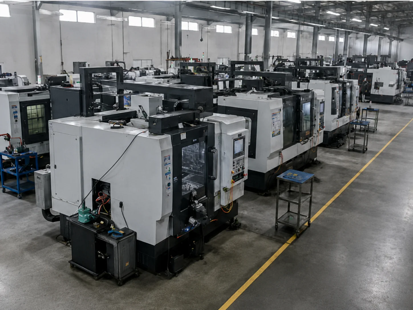
20+ Years CNC Experience & 153 Precision Machines
Standard Tolerance Reference ±0.01 mm
Prototype to Batch Production
Custom CNC Milling3-Axis to 5-Axis CapabilityMade to Your DrawingMulti-Surface Geometry Review
The goal is not to use the most complex machine. The goal is to control the part's functional geometry with an efficient manufacturing route.
3-AXIS CNC MILLING
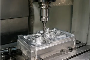
Best Fit: Open Pockets, Top-Face Features, Simple Plates, Brackets, Accessible Housings.
Efficient setup. Suitable for accessible geometry where features are concentrated on one or two parallel planes.
MULTI-SIDE / INDEXED MACHINING
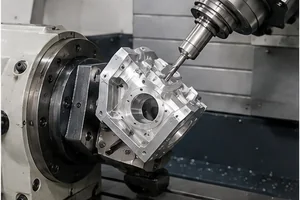
Best Fit: Side Holes, Multiple Mounting Faces, Connector Openings, Cross-Face Features.
Engineering Focus: Datum transfer, Re-Clamping accuracy, Cross-Face Relationship.
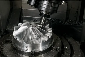
5-AXIS CNC MILLING
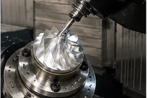
Best Fit: Angled Faces, Compound Geometry, Multiple Related Surfaces, Hard-to-Reach Features, Complex Housings.
Engineering Focus: Tool Access, Reduced Repositioning Where Beneficial, Feature Relationship.
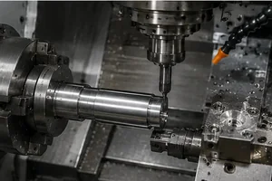
TURN-MILL / HYBRID ROUTE
Best Fit: Rotational Base Geometry + Milled Flats, Slots, Cross Holes, Radial Threads.
Combines turning and milling in one setup to maintain concentricity and feature alignment on cylindrical base parts.
Why CNC Milled Parts Fail Even When Individual Dimensions Pass
Procurement risks usually happen at the interface level—not just the single dimension level.
01
Individual Features Pass but the Complete Milled Geometry Fails
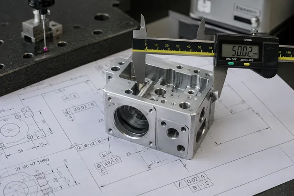
Holes and pockets measure correctly, but their relationship to the functional datum is wrong, causing assembly interference.
02
Multi-Surface Features Lose Alignment During Setup Transfers
Re-clamping the part for multi-side machining introduces angular errors and position stack-up across faces.
03
Prototype Passes, but Critical Milling Geometry Drifts in Production
Tool wear, thermal changes, and fixture conditions cause dimensions to drift across larger batch runs.
04
Mounting Faces Lose Flatness
Thickness is correct, but the face is not flat, causing the component to rock or distort when bolted.
05
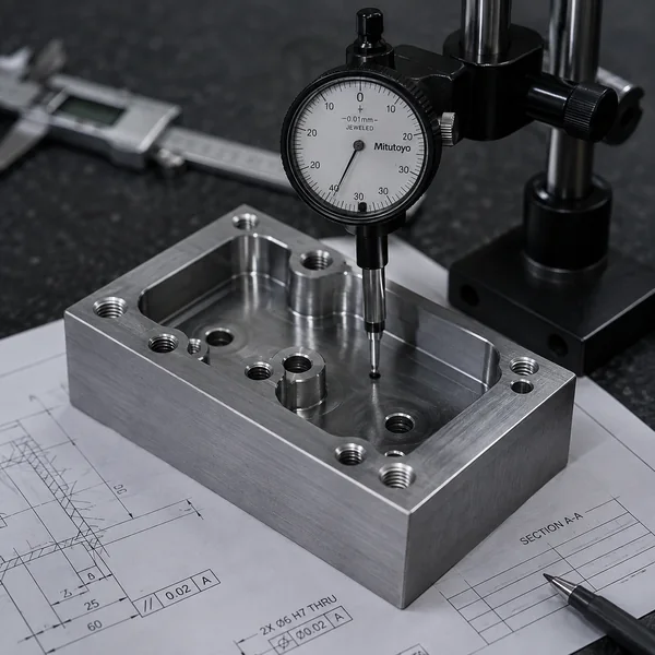
Deep Pockets Cause Tool Deflection
Long tool reach leads to chatter, wall taper, and poor surface finish at the bottom of cavities.
06
Thin-Wall Parts Warp
Residual stress and clamping force cause the part to distort after it is released from the machine.
07
Fastener Interface Fails
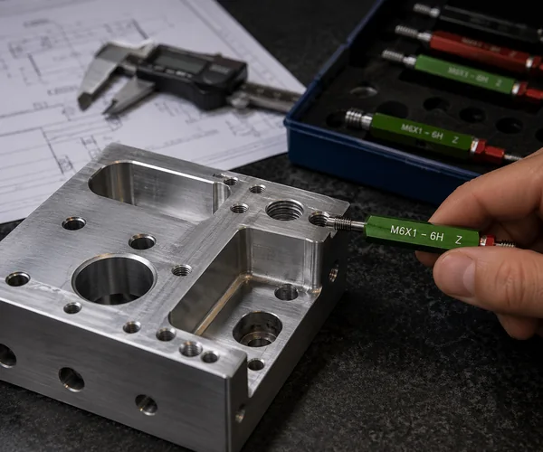
Thread gauge passes, but counterbores, entry chamfers, or dowel relationships prevent fastener seating.
08
Internal Passages Retain Burrs
Cross-hole intersections in manifolds hide chips and rolled edges that disrupt fluid flow.
09
Poor Tool Access Drives Cost
Sharp internal corners and undercut features look simple in CAD but require expensive specialized tooling.
10
Post-Processing Changes Interfaces
Anodizing or plating builds up on critical dowel holes and threads, ruining the final fit.
Individual Features Pass, but the Complete Milled Geometry Fails
The Challenge:
Hole Diameter: PASS
Pocket Size: PASS
Bore: PASS
Mounting Face: PASS
Feature-to-Datum Relationship: FAIL
Final Assembly: FAIL
This typically affects housings, brackets, fixtures, and sensor components. It happens when the wrong functional datum is chosen, hole patterns shift relative to each other, or locating features are referenced from the wrong surface, causing datum stack-up. The result? Mating holes do not align, connectors don't fit, and internal components cannot seat.
LuckyHxs Approach:
We review assembly-related drawing features, identify the true functional datum, separate locating features from clearance features, and plan the setup directly from critical features. We verify CTQ relationships before shipment.
While Clamped: PASS After Release: GEOMETRY CHANGES
RisksResidual Stress, Workholding Force, Uneven Material Removal, Deflection.
LuckyHxs Approach:
We define primary datums, evaluate setup counts, and utilize multi-axis routes where useful to reduce repositioning. We review tool reach, use practical internal radii, plan roughing/finishing stages to manage stress, and inspect critical geometry *after* release from workholding.
Prototype Approval ≠ Automatic Production Repeatability
Prototype Passes, but Critical Milling Geometry Drifts in Production
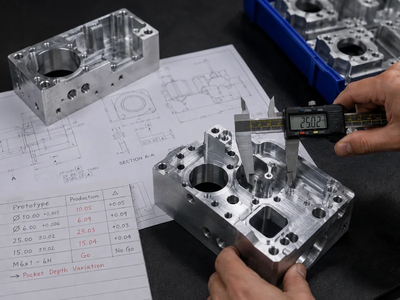
The prototype was perfect: Hole patterns, flatness, threads, and surface finish all passed. But in repeat production, hole patterns move, pocket depths change, flatness shifts, and thread fits vary.
Why It Happens:
Tool wear, drill wear, fixture degradation, tool offset variations, material lot differences, thermal changes during long runs, and variations in manual deburring or surface processing.
LuckyHxs Approach:
Drawing Revision Review & Material Confirmation
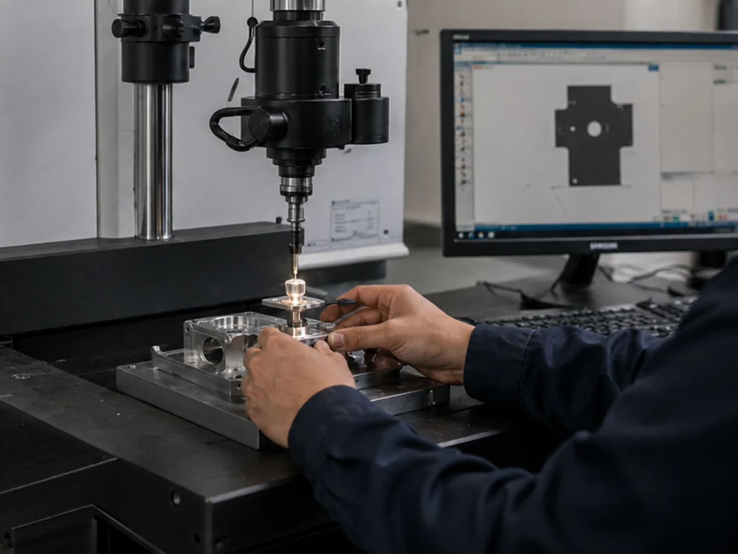
First Article Verification with CTQ Definition
In-Process Inspection for Holes, Pockets, and Faces
Tool Condition Monitoring & Burr Review
Repeat-Order Requirement Retention
A Dimension Only Has Meaning When It Is Referenced Correctly
Locating Features ≠ Fastening Features. Do not apply the same precision logic to every hole.
PRIMARY DATUM
Where does the component physically seat?
Establishes the main plane of contact and orientation for the entire part.
SECONDARY DATUM
What controls lateral orientation?
Prevents rotation and establishes X/Y coordinate origin.
LOCATING FEATURE
What controls repeatable position?
Dowel, Pilot, Boss, Precision Bore.
Requires tight positional and diametric tolerance.
FASTENING FEATURE
What retains the component?
Clearance Hole, Thread, Counterbore.
Needs clearance to allow locating features to work.
Engineering Focus:
Functional Datum Identification
Hole Position & True Position Where Specified
Hole-to-Face Relationship
Pilot Relationship & Assembly Dimensions
A Correct Thickness Does Not Guarantee a Functional Mounting Plane
A mounting face is a functional interface—not a cosmetic surface.
THICKNESSControls distance between surfaces. It does not mean the surfaces are flat.
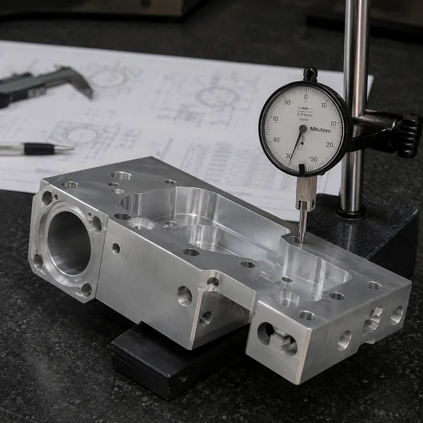
FLATNESSControls the shape of one functional face, preventing rocking or sealing gaps.
PARALLELISM & PERPENDICULARITYControls relationship and orientation between two or more surfaces.
FREE-STATE GEOMETRYConfirms whether the part changes shape after being unclamped from the machine.
Deep Pockets Are Not Just Shallow Pockets With More Depth
Longer tool reach → More deflection risk → More chatter → Less stable wall geometry → Longer machining time.
The "Perfect 90° Corner" Myth
A perfect 90° internal corner cannot be directly produced by a standard rotating circular end mill. It requires alternative processes (like EDM) or design compromises (like dog-bone corners).
DFM Considerations We Review:
• Pocket Depth to Slot Width Ratio
• Practical Internal Radius vs. Assembly Need
• Tool Reach and Rigidity
• Wall Height and Finishing Strategy
Clamped Geometry PASS Does Not Guarantee Free-State Geometry PASS
The correct thin-wall strategy depends on material, geometry, size and tolerance—there is no universal "minimum wall thickness."
The Thin-Wall Risk
Applicable to Housings, Lightweight Brackets, Optical Components, EV Components, Pocketed Plates, and Enclosures.
Residual Stress release after material removal
Clamping Force distortion
Uneven Material Removal
Heat generation and Tool Pressure
Tall Wall Deflection
LuckyHxs Approach
We review wall geometry and raw material condition, plan roughing sequences to avoid material imbalance, control workholding carefully, separate rough/finish stages, and inspect functional geometry after release.
Thread Gauge PASS Does Not Mean the Fastener Interface Will Work
A fastener interface is a system. If the thread passes but the counterbore is too shallow, the screw bottoms out. If the thread axis tilts, the head cannot seat.
What We Check
• Thread Size & Pitch
• Usable Thread Depth
• Entry Chamfer
• Thread Axis & Position
• Counterbore / Countersink
• Dowel-to-Clearance Relationship
Typical Failures
• Screw bottoms out
• Fastener head cannot seat
• Hole pattern shifts
• Dowel hole and bolt hole compete
Hole Diameter PASS Does Not Mean the Internal Passage Is Clean
Crucial for Manifolds, Valve Bodies, Fluid-Control Blocks, and Multi-Port Blocks.
The Internal Interface Risk
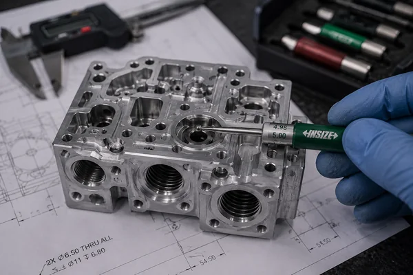
Cross holes, radial ports, thread exits, and bore intersections create internal edges. If not managed, internal burrs, chips, and rolled edges can cause partial flow obstruction or thread damage.
Our Control Flow:
Cross Drilling
Intersection Review
Feature-Specific Deburring
Internal Cleaning
Visual / Magnified Review Where Appropriate
Final Verification
Control the Part Through Finishing, Inspection & Final Use
A. Post-Processing
Machining complete does not always mean the final interface is complete. Clarify if critical dimensions apply before or after finishing.
Specific capability confirmed according to part geometry, material and inspection requirements.
C. Applications
Precision CNC milling for demanding industrial sectors.
• Industrial Equipment
• Robotics & Automation (Brackets/Mounts)
• Automotive & EV
• Electronics (Housings/Heat Sinks)
• Sensors & Instruments
• Optical / Machine Vision
• Fluid-Control (Manifolds)
• Fixtures & Tooling
A CNC Manufacturing Partner You Can Verify
Real capabilities, real compliance, real production.
Certificates & Compliance Documents
ISO9001
CE
REACH & ROHS
TEST REPORT
Customer Factory Visits
Factory Visit
Production Review
Technical Discussion
Quality Review
See How LuckyHxs CNC Parts Are Machined and Inspected
What Is CNC Milling and What Parts Can It Make?
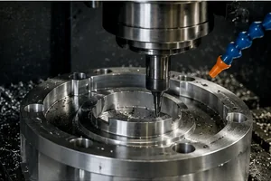
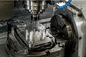
CNC milling is a subtractive manufacturing process in which rotating cutting tools remove material from a workpiece to create pockets, holes, slots, flat surfaces, profiles and complex multi-surface geometry.
Common CNC Milled Parts
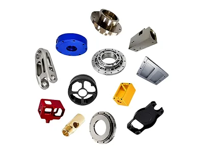
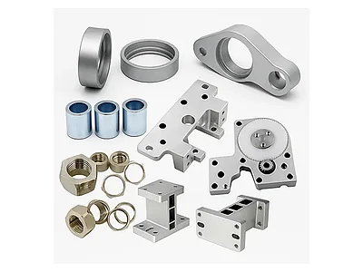
We regularly manufacture: Housings, Brackets, Manifolds, Plates, Fixtures, Sensor Components, Optical Components, Heat Sinks, and Complex Multi-Axis Parts.
Feature to Milling Function
Pocket → Internal Clearance
Hole Pattern → Assembly
Dowel Hole → Location
Bore → Fit / Alignment
Mounting Face → Stable Contact
Slot → Adjustment
Cross Hole → Fluid / Mechanical Interface
Angled Surface → Multi-Axis Interface
When Is CNC Milling a Good Fit?
When a part needs flat or contoured surfaces, pockets, hole patterns, multiple faces, threaded features, datum-controlled relationships, complex 3D geometry, in prototype or production quantities.
Core Insight: CNC milling is not defined by the machine alone—it is defined by how the final geometry must function in the customer's assembly.
3-Axis vs 4-Axis vs 5-Axis CNC Milling: Which Does Your Part Need?
The best process is the simplest route that controls the required geometry reliably.
3-AXIS
Best Fit: Open Geometry, Top Features, Plates, Simple Brackets, Accessible Pockets.
Potential Limitation: More re-fixturing is required for multiple sides, which can introduce tolerance stack-up.
4-AXIS / INDEXED
Best Fit: Multiple Side Features, Rotational Indexing, Side Holes, Repeated Angular Features.
Does fewer setups actually improve manufacturing efficiency?
What inspection is required?
How Much Does CNC Milling Cost?
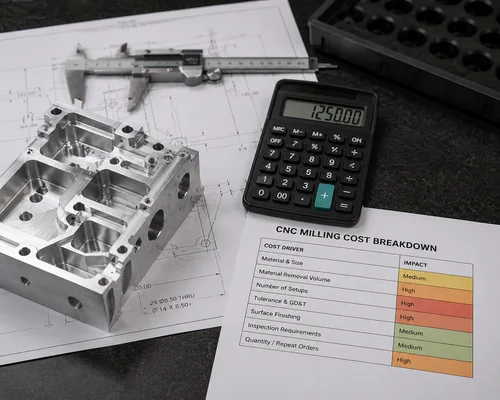
There is no universal price for CNC milling. Two parts with similar outside dimensions can have very different costs if one requires only a profile and several clearance holes while another needs five-side machining, deep pockets, thin walls, tight positional tolerances and detailed inspection.
11 Cost Drivers
Material
Raw Material Size
Material Removal Volume
Number of Machined Faces
Number of Setups
Pocket Depth / Tool Reach
Tolerance & GD&T
Threads / Holes / Special Features
Surface Finishing
Inspection Requirements
Quantity / Repeat Orders
Why Can CNC Milling Become Expensive?
Deep narrow pockets, tiny internal radii, tight tolerances everywhere (instead of just where needed), multiple setups, long-reach tools, thin-wall machining, difficult materials, complex inspection, and very low quantities.
How To Reduce Cost Without Hurting Function
Use tight tolerances only on functional features
Use practical internal radii
Avoid unnecessary deep pockets
Separate locating holes from clearance holes
Clarify final-finish dimensions
The lowest unit price does not always come from removing precision—it comes from applying precision only where the assembly needs it.
Frequently Asked Questions About CNC Milling Manufacturing Services
What is CNC milling?
CNC milling is a subtractive manufacturing process that uses rotating cutting tools to remove material from a workpiece, creating specific functional geometry like pockets, holes, flat faces, and 3D contours based on CAD drawings.
What is the difference between 3-axis and 5-axis CNC milling?
3-axis milling moves along X, Y, and Z axes, ideal for parts with features on one or two faces. 5-axis adds two rotational axes, allowing the tool to approach from almost any angle, which is valuable for complex parts, reducing setups, and maintaining relationships across multiple faces.
What materials can LuckyHxs CNC mill?
We commonly mill Aluminum (6061, 7075), Stainless Steel (303, 304, 316), Brass, Copper, Free-Machining Steel, project-specific Titanium, and engineering plastics like POM and Nylon.
What tolerances can CNC milling achieve?
LuckyHxs standard tolerance reference is ±0.01 mm. Actual achievable tolerance depends on material, part size, geometry, specific feature (hole vs deep pocket), setup strategy, and inspection requirements.
How much does CNC milling cost?
Cost is driven by material, raw size, material removal volume, number of setups, feature complexity (like deep pockets), tolerances, finishing, and quantity. We provide accurate quotes after reviewing your specific drawing.
Why is CNC milling expensive for some parts?
High costs usually stem from difficult tool access, deep narrow pockets requiring long tools, unnecessarily tight GD&T across non-functional surfaces, multiple manual setups, and complex inspection requirements.
Can you machine complex 5-axis parts?
Yes, LuckyHxs supports 5-axis machining. The specific manufacturing route (whether 3-axis, indexed, or simultaneous 5-axis) is confirmed after engineering review of your drawing to ensure the most reliable and efficient process.
Can LuckyHxs support prototype and repeat production?
Yes. We handle initial prototype runs to validate the design and manufacturing route, and then transition to batch or repeat production while retaining the critical quality requirements and setup data to ensure consistency.
What information should I send for a CNC milling quote?
Please send 2D Drawings (PDF) and 3D CAD models (STEP/IGES). Include material specifications, quantity, critical dimensions, GD&T, functional datums, thread details, surface finish, post-processing needs, and inspection requirements.
Need a CNC Milled Part That Fits the Complete Assembly?
Send your 2D/3D drawing, material, quantity, functional datums, critical hole positions, pockets, bores, threads, surface finish and inspection requirements. LuckyHxs will review the machining route before quotation.
Trusted CNC Partner
High-Precision CNC Machining
Partner with an industry leader. We provide OEM and ODM support with uncompromising quality, offering fast 3-day sample delivery for your critical projects.