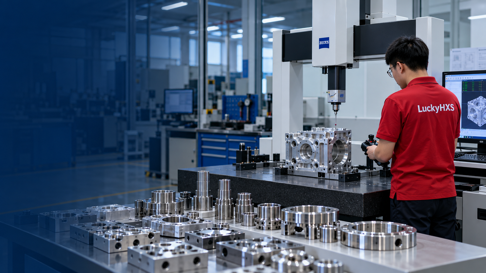
CNC Milling Parts Manufacturer for Custom Components
LuckyHXS manufactures custom housings, brackets, mounting plates, adapter plates, manifold blocks, heat sinks, fixtures and complex CNC milled components from customer drawings. We review functional datums, material, tolerance, surface finish and inspection requirements before selecting the machining route.
Metal and engineering-plastic parts for prototypes, sample validation and repeat production.
PDF, STEP, DWG and IGES files can be reviewed with your material, quantity and critical-feature requirements.
Custom CNC Milling Parts Built Around Functional Geometry
A CNC milled part is not defined only by its outside dimensions. Pockets, mounting faces, sealing surfaces, hole patterns, internal threads and relationships between multiple datums determine how the part should be held, machined and inspected.
Supply Type
Made-to-drawing CNC milled components
Typical Geometry
Pockets, slots, steps, threaded holes, bores, sealing faces and multi-side features
Material Scope
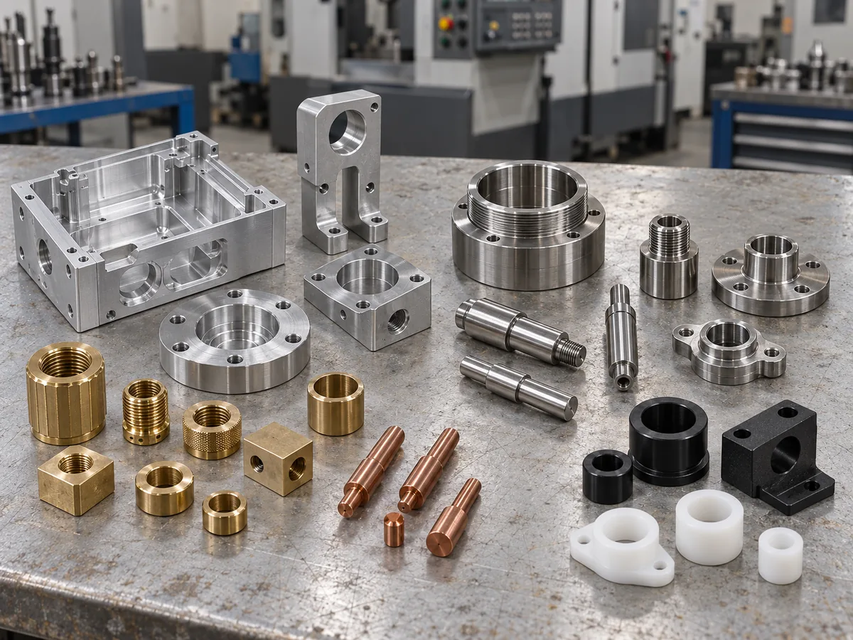
Aluminum, stainless steel, brass, copper, free-machining steel and selected engineering plastics
Project Stage
Prototype parts, sample validation, low-volume requirements and repeat orders
Drawing Inputs
2D drawings and 3D CAD models
Engineering Focus
Functional datums, mating interfaces, post-finish dimensions and inspection access
The manufacturing plan is developed around the part’s function and drawing requirements rather than a standard catalog size.
What Are Custom CNC Milling Parts?
Custom CNC milling parts are components produced by removing material from a metal or plastic workpiece with rotating cutting tools. Milling is commonly selected for prismatic parts with flat faces, pockets, slots, hole patterns, threaded features and surfaces that must relate accurately to one another.
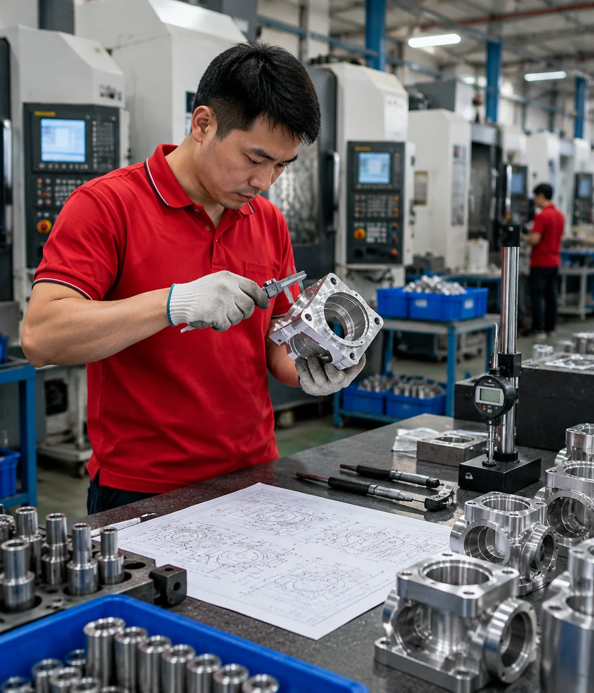
A CNC milling parts manufacturer should do more than reproduce separate dimensions. The supplier must understand which surfaces locate the part, which holes control assembly, which features will be affected by finishing and how the critical relationships will be verified.
Typical parts include:
- Equipment housings and electronic enclosures
- Brackets, mounts and structural components
- Mounting plates, adapter plates and precision bases
- Fluid-control manifolds and valve blocks
- Heat sinks and thermal-management components
- Jigs, fixtures and tooling components
- Sensor, camera and optical mounts
- Multi-sided and complex custom parts
This page covers components manufactured from customer drawings, not replacement parts for CNC milling machines.
Custom CNC Milling Parts We Manufacture
Each product family is manufactured to project-specific drawings, materials, dimensions and functional requirements.
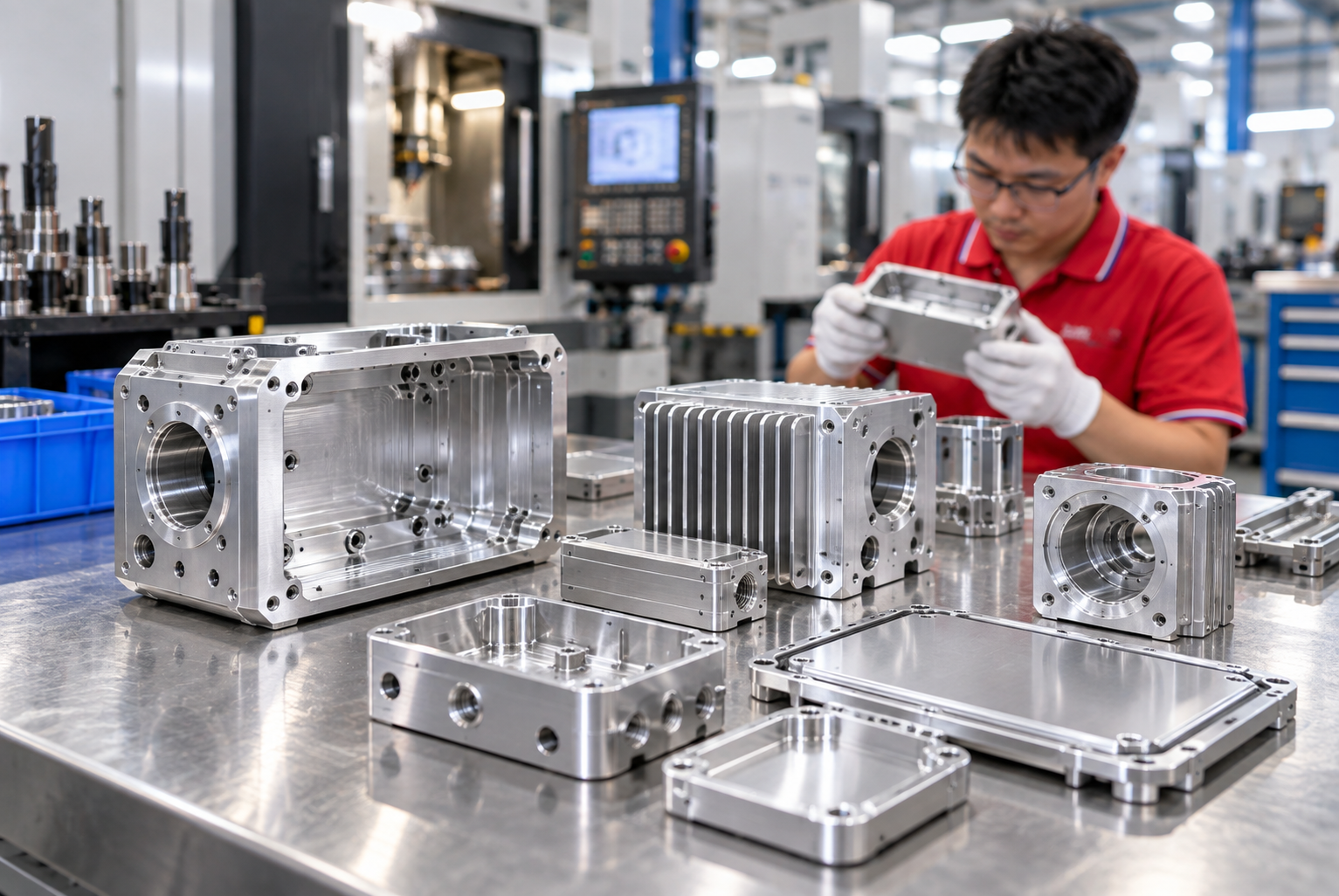
CNC Machined Housings & Enclosures
For sensor, motor, electronic and control equipment requiring internal cavities, connector openings, mounting points and stable sealing or assembly surfaces.
Selection focus: cavity depth, wall thickness, interface position and post-finish fit.
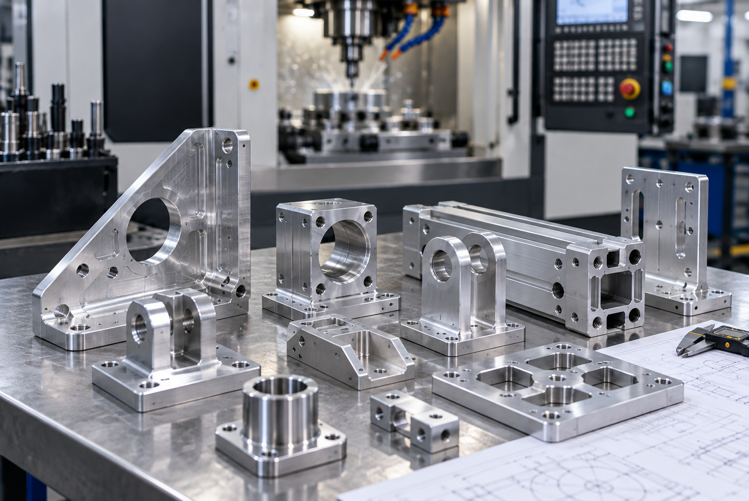
CNC Brackets, Mounts & Structural Parts
For automation, robotics, automotive, optical and industrial assemblies requiring rigid mounting surfaces and controlled relationships between hole patterns.
Selection focus: datum structure, hole position, parallelism and perpendicularity.
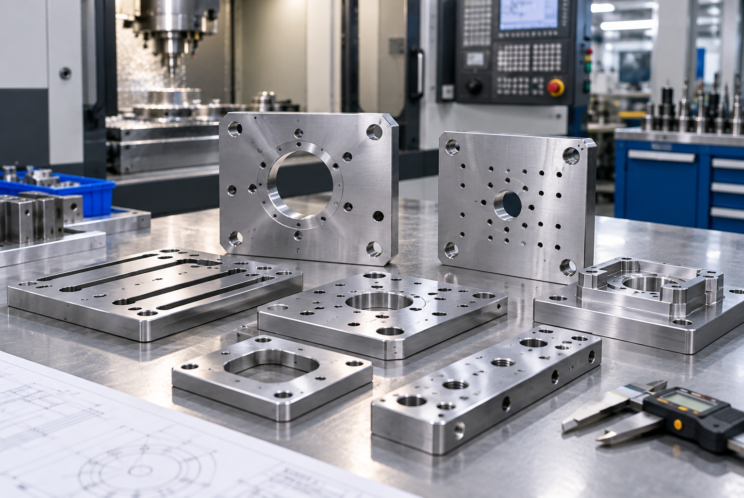
Mounting Plates, Adapter Plates & Precision Bases
For connecting equipment, motors, sensors and motion systems with different mounting patterns or center positions.
Selection focus: flatness, plate thickness, dowel locations, interface alignment and surface finish.
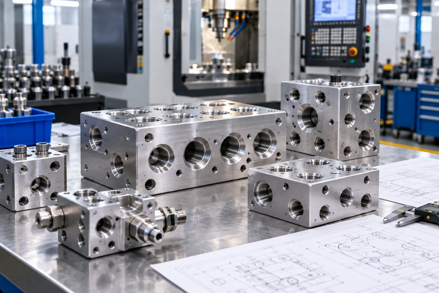
Manifold & Fluid-Control Blocks
For hydraulic, pneumatic, gas and cooling systems containing cross-drilled passages, threaded ports and sealing faces.
Selection focus: port type, passage intersection, internal deburring, cleanliness and sealing surfaces.
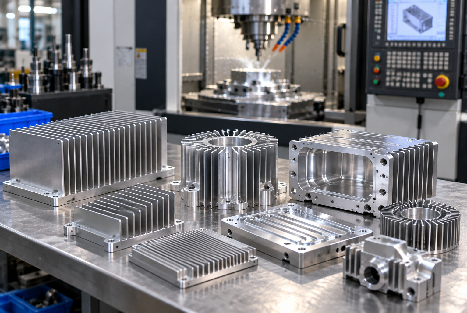
CNC Heat Sinks & Thermal Management Parts
For power electronics, LED systems, controllers and communication equipment requiring machined mounting faces and heat-dissipation features.
Selection focus: base flatness, fin geometry, mounting interface and surface treatment.
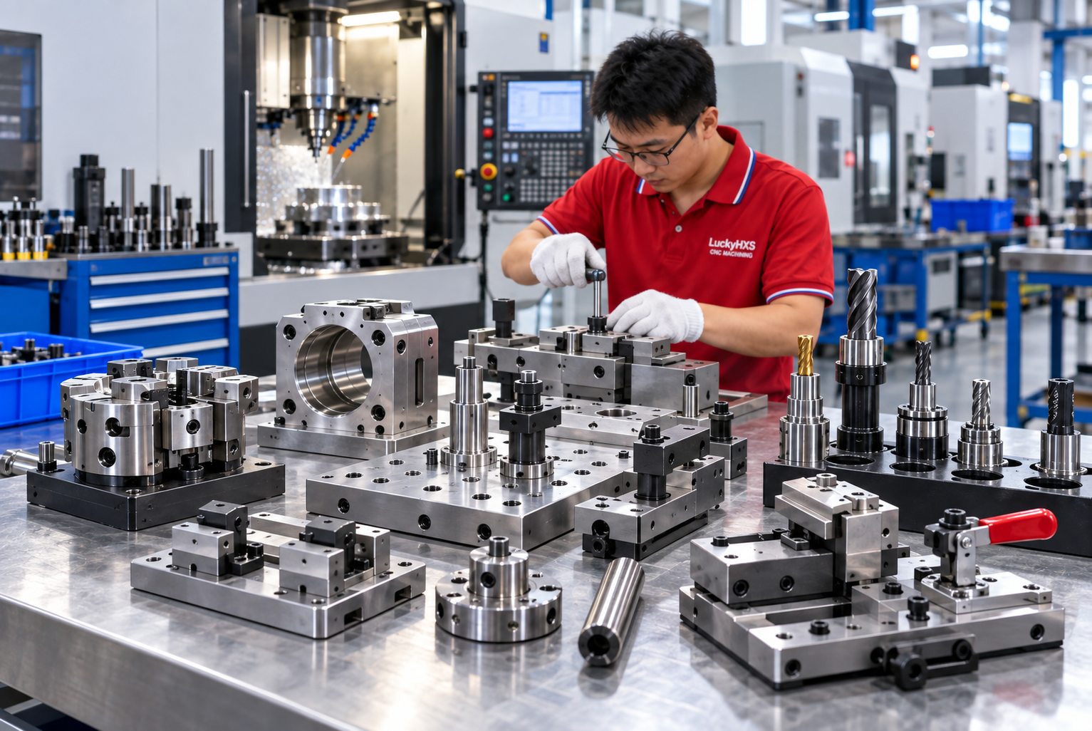
CNC Jigs, Fixtures & Tooling Components
For assembly, inspection and automation processes requiring repeatable locating points, clamping features and replaceable wear components.
Selection focus: locating datum, repeatability, clamping access and serviceable components.
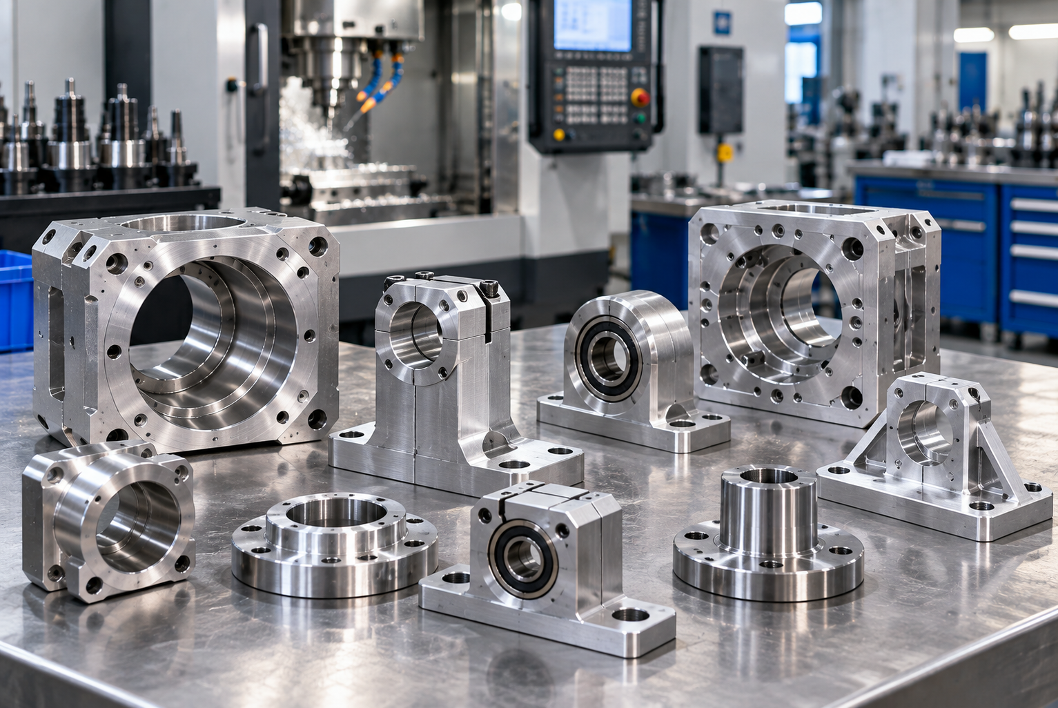
Motor, Bearing & Drive Mounts
For servo motors, electric drives and rotating equipment requiring aligned bores, bearing fits and controlled mounting faces.
Selection focus: bore fit, common axis, face relationship and mounting-hole position.
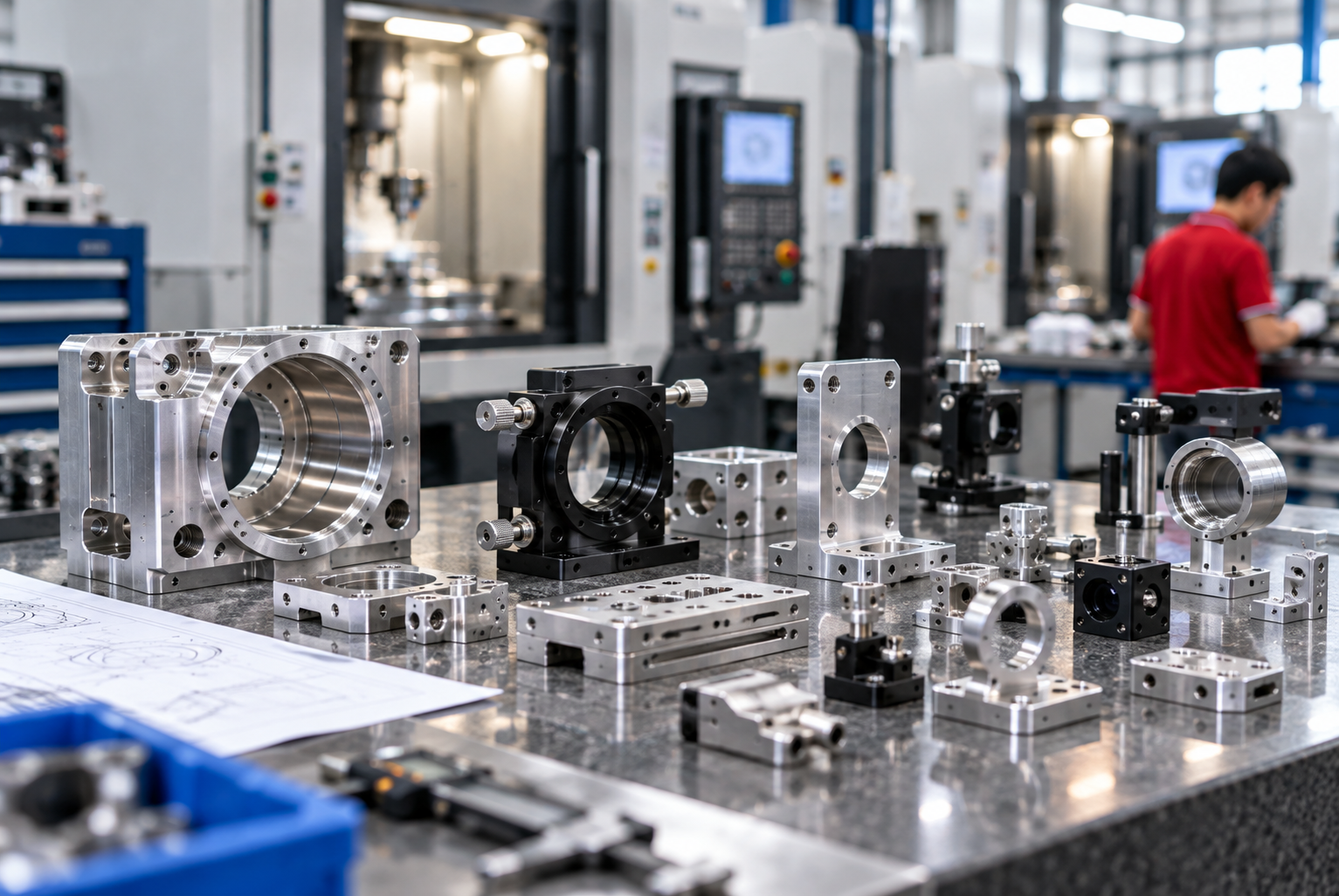
Sensor, Camera & Optical Mounts
For machine vision, measurement, automation and optical assemblies requiring stable positioning and controlled angular relationships.
Selection focus: optical axis, sensor position, angular accuracy and adjustment features.
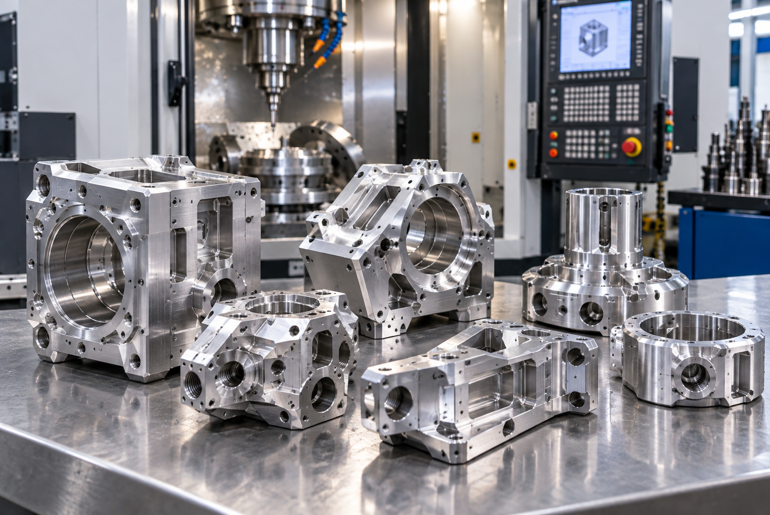
Complex Multi-Sided CNC Milled Parts
For non-standard components containing pockets, compound angles, grooves, threaded holes and related features on multiple faces.
Selection focus: tool access, setup count, datum transfer and multi-axis feasibility.
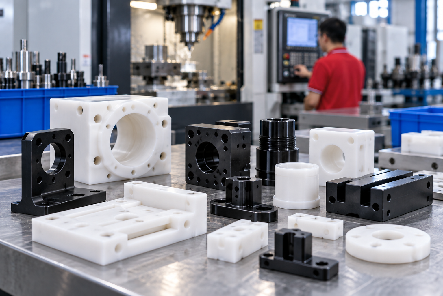
Engineering Plastic CNC Milled Parts
For POM, PTFE, Nylon and other selected engineering-plastic components used for insulation, low friction, wear control or weight reduction.
Selection focus: material stability, wall thickness, thread design and operating environment.
Milling Problems That Often Appear During Assembly
A part can meet several isolated dimensions and still fail in the final assembly. The manufacturing and inspection plan should protect the relationships that make the component function.
Dimensions Pass, but the Assembly Does Not
Separate features may be within size tolerance while the complete hole-to-pocket, bore-to-face or pattern-to-datum relationship is incorrect.
Thin Walls Move After Unclamping
Removing a large amount of material can reduce rigidity and release internal stress, affecting flatness and final fit.
Mounting Holes Do Not Align
A correct hole diameter does not guarantee that the complete pattern matches the mating frame, bracket or device.
Burrs Remain Inside Cross Holes
Hidden burrs at passage intersections can obstruct flow, damage seals or contaminate an assembly.
Surface Finishing Changes Critical Fits
Anodizing, plating and other treatments can affect threaded holes, bearing fits, dowel holes and sealing interfaces.
The Approved Sample Is Not Repeated
Tool wear, fixture changes, material variation and uncontrolled drawing revisions can create differences between a sample and later production.
LuckyHXS reviews functional datums, critical interfaces, finishing allowances and inspection access before production planning.
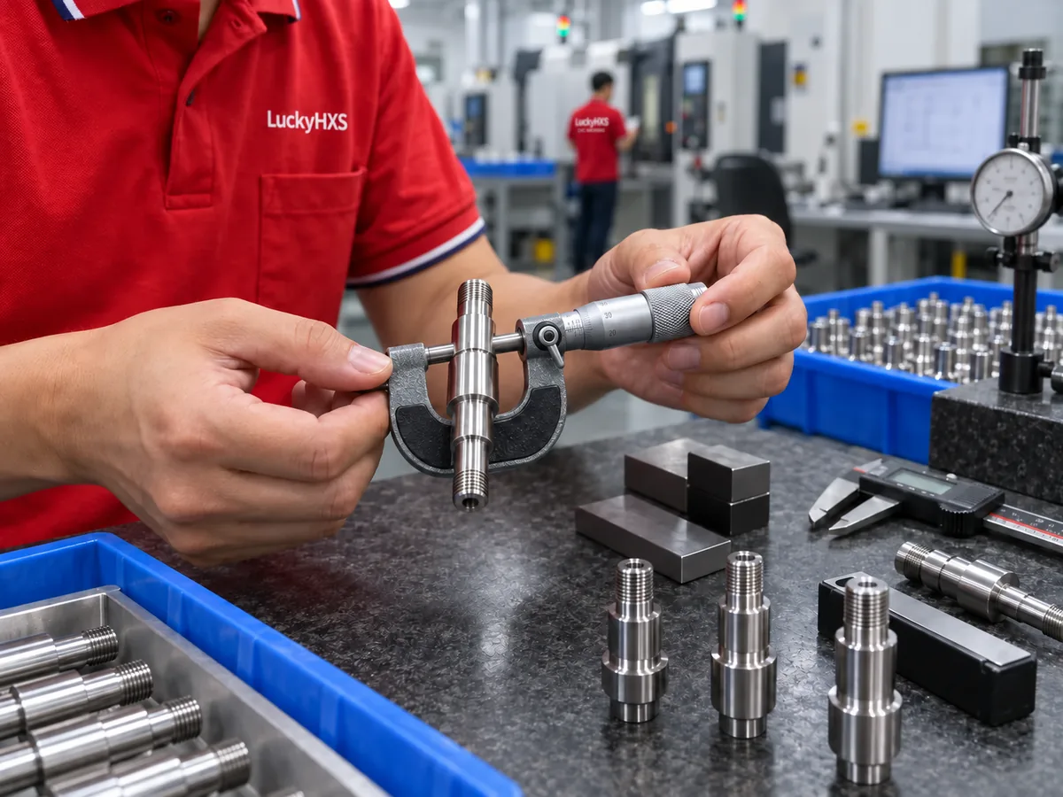
Manufacturing Decisions Start With the Drawing
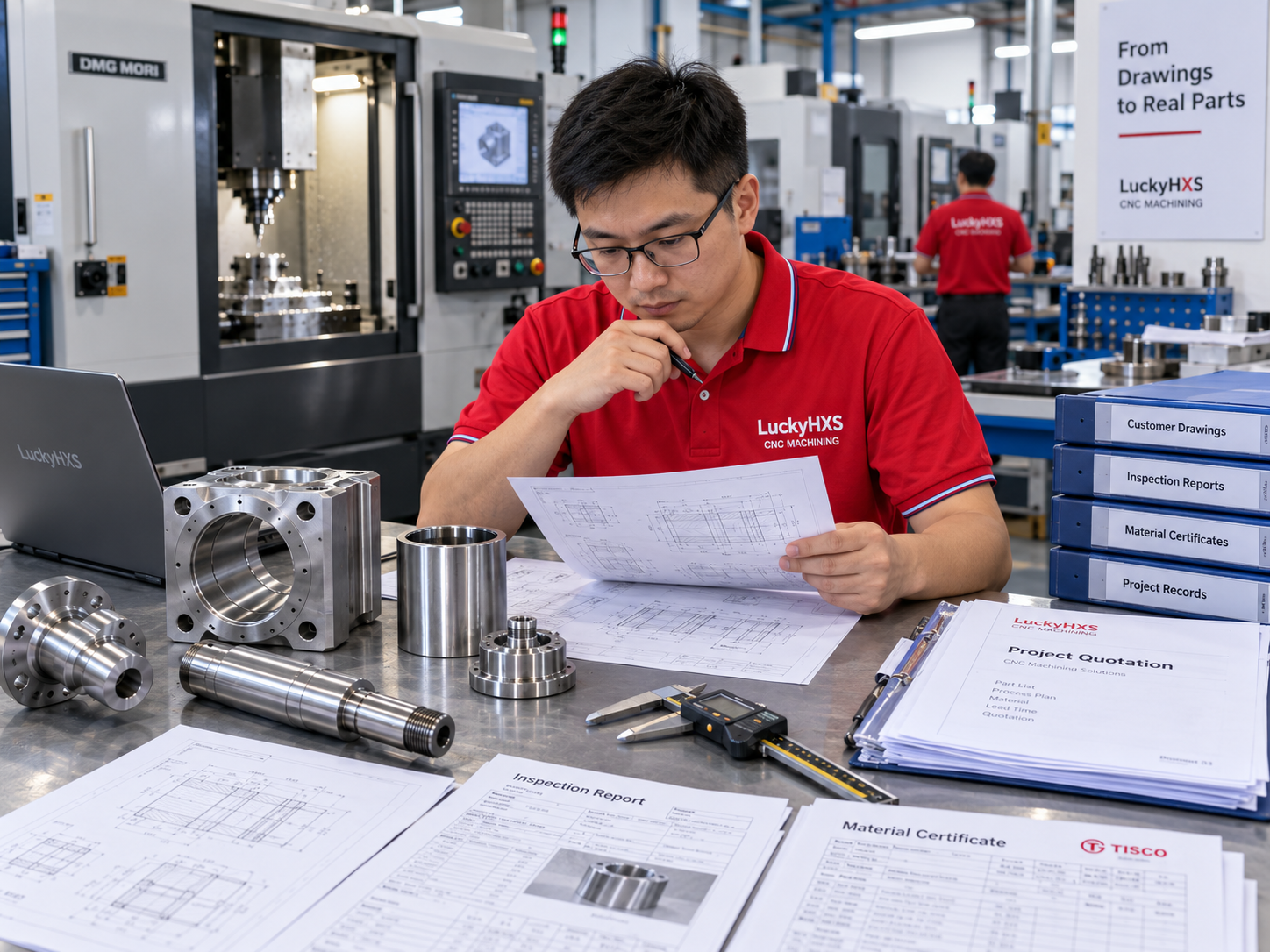
Identify the Functional Datum
The primary locating surface and related interfaces must be understood before machining and inspection references are selected.
Group Related Critical Features
Mating holes, bores, sealing faces and alignment features should be controlled as functional relationships, not unrelated dimensions.
Plan Workholding and Tool Access
The setup must provide enough rigidity and access while limiting unnecessary datum transfers between operations.
Allow for Secondary Finishing
Masking, coating thickness and post-finish inspection must be considered wherever the final fit can change.
Match Inspection to Function
The measuring method should verify the feature relationship that matters to assembly, such as hole position, flatness, bore alignment or cross-hole cleanliness.
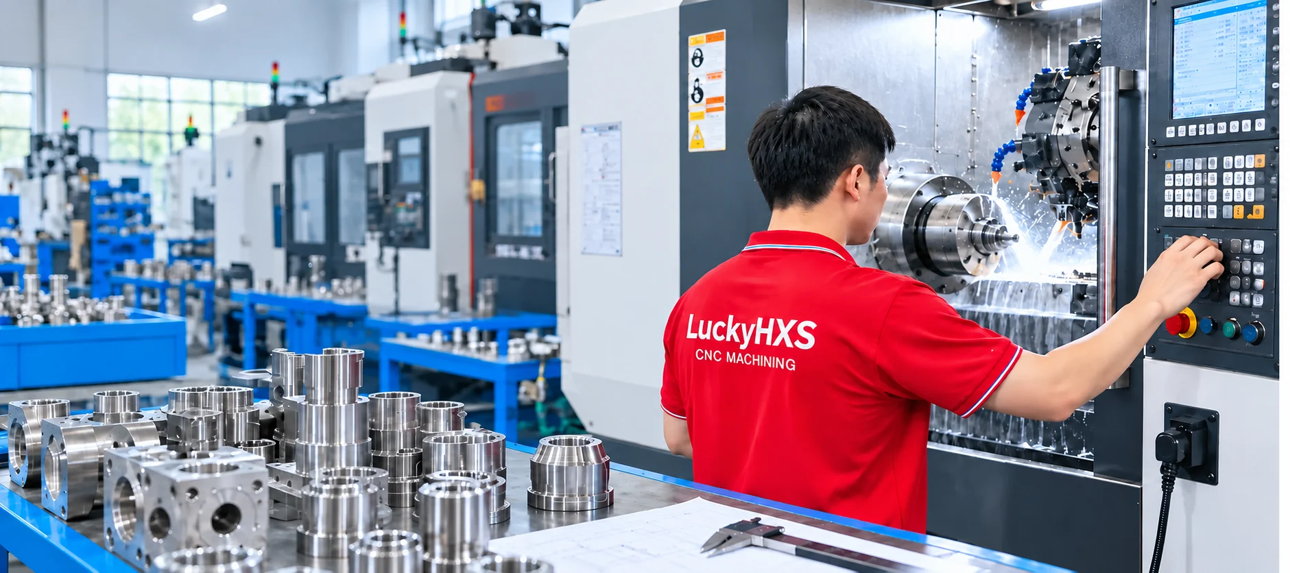
Choose the Machining Route From Part Geometry
More axes do not automatically make a process better. The suitable route depends on tool access, feature relationships, setup count, material, tolerance and inspection requirements.
| Process Route | Suitable Geometry | Main Selection Reason | Typical Parts |
|---|---|---|---|
| 3-Axis CNC Milling | Plates, pockets, slots, holes and accessible top-side features | Efficient when the required features can be reached from standard directions | Mounting plates, simple brackets and bases |
| 4-Axis or Rotary Positioning | Side holes, features around a body and repeated angular positions | Can reduce manual repositioning for suitable multi-face geometry | Motor mounts, indexed components and ported parts |
| 5-Axis Evaluation | Compound angles, complex surfaces and related features across several faces | May reduce setups and protect multi-face relationships when the geometry justifies it | Complex housings, optical mounts and structural parts |
| Drilling, Tapping and Boring | Threaded holes, dowel locations, ports and controlled bores | Completes connection and locating features required by the assembly | Manifolds, plates and bearing mounts |
| Turn-Mill Coordination | Cylindrical geometry combined with flats, slots, cross holes or mounting faces | Keeps rotational and milled features within a coordinated process plan | Drive components and hybrid custom parts |
| Wire EDM Support | Sharp internal profiles or features that are difficult to reach with a rotating cutter | Considered only where the geometry requires an alternative process | Selected tooling and special profiles |
The final route is confirmed after reviewing the drawing, material, quantity and critical feature relationships.
Design Details That Change CNC Milling Difficulty
Deep, Narrow Pockets
Long tool reach can increase deflection, vibration and machining time. A larger corner radius or reduced depth may improve access where the design permits.
Tall or Thin Walls
Low rigidity can cause movement during cutting and distortion after unclamping. Wall thickness, material removal sequence and workholding should be reviewed together.
Sharp Internal Corners
Rotating cutters leave an internal radius. A realistic corner radius, relief feature or alternative process may be required.
Features on Multiple Faces
Every new setup can introduce additional handling and datum-transfer risk. Related features should be grouped wherever the geometry allows.
Tight Tolerances Everywhere
Applying the same tight tolerance to non-functional dimensions increases machining and inspection effort without necessarily improving the assembly.
Caution note: Any design or tolerance change requires customer approval before production.
Materials for Custom CNC Milling Parts
Material selection affects cutting behavior, wall stability, corrosion resistance, weight, surface finishing and the final cost of the component. Confirm the grade and condition rather than specifying only a general material family.

| Material | Available Grades or Types | Common Uses | Manufacturing Watch Points |
|---|---|---|---|
| Aluminum | 6061, 6063, 7075, 2024 and 5052 where suitable | Housings, brackets, plates, heat sinks and structural components | Thin-wall distortion, cosmetic surfaces and anodizing allowance |
| Stainless Steel | 303, 304, 316L and 316F where suitable | Instrument parts, fluid-control components, mounts and corrosion-resistant housings | Tool wear, heat, internal burrs and thread quality |
| Brass and Copper | H59, H62, H65, C3602, C3604 and project-specific copper | Connectors, conductive components, inserts and selected fluid-control parts | Material grade, surface marking, burr control and plating requirements |
| Free-Machining Steel | 1214 and 1215 | Bases, fixtures and repeat machined components where suitable | Corrosion protection, plating allowance and final application environment |
| Engineering Plastics | POM, PTFE, Nylon and selected project-specific materials | Insulating, low-friction, wear-resistant and lightweight components | Dimensional stability, clamping pressure, thread design and temperature conditions |
Material availability and grade suitability are confirmed against the drawing and application before quotation.
Plan the Final Fit Before Surface Finishing
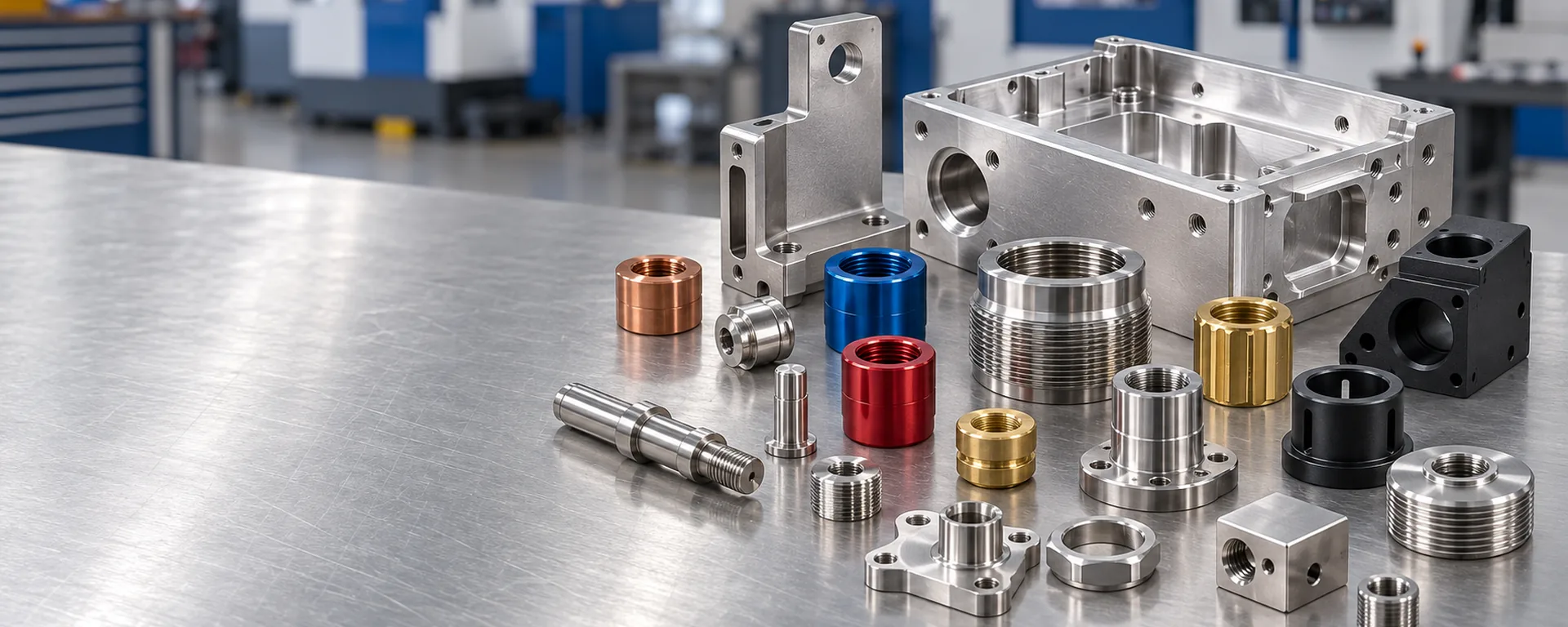
Machining completion does not always mean the functional part is complete. Anodizing, plating, black oxide, sandblasting and polishing can change dimensions, surface texture or the condition of critical interfaces.
Anodizing
Used on suitable aluminum parts for surface protection and appearance. Critical fits, threads and conductive areas may require allowance or masking.
Sandblasting
Creates a more uniform matte appearance but should be reviewed around sealing faces and dimensionally sensitive surfaces.
Nickel Plating
Consider coating thickness on bores, threads and mating features before the final dimension is defined.
Zinc Plating
Used on suitable steel components where corrosion protection is required.
Black Oxide
A finishing option for suitable steel parts where application and corrosion requirements permit.
Polishing
Used where smoother surfaces or specific appearance requirements are needed.
Confirm whether the drawing dimensions apply before or after finishing, especially for bores, threads, dowel holes, mounting faces and sealing surfaces.
Tolerance Is Useful Only When It Protects Function
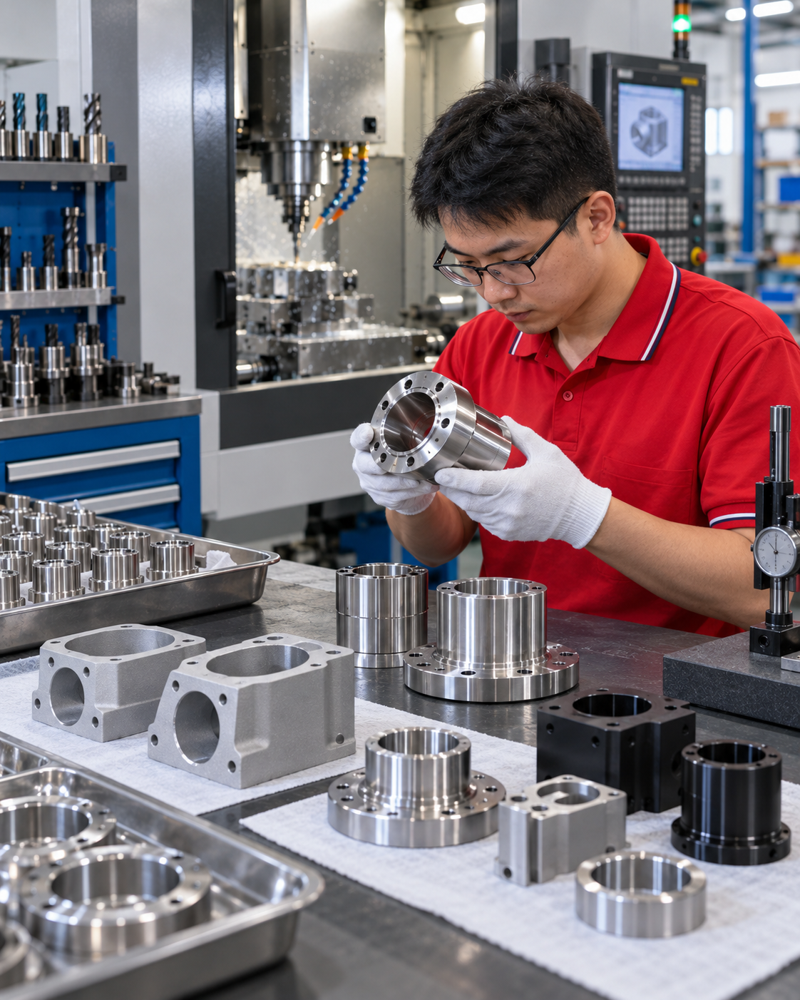
A standard machining tolerance around ±0.01 mm may be reviewed for suitable features, but the achievable result depends on part geometry, material, wall thickness, setup, finishing and inspection method. Tighter requirements should be identified only on the features that control function.
The inspection plan should be agreed around the drawing’s critical-to-quality features rather than applying the same method to every dimension.
From First Article to Repeat CNC Production
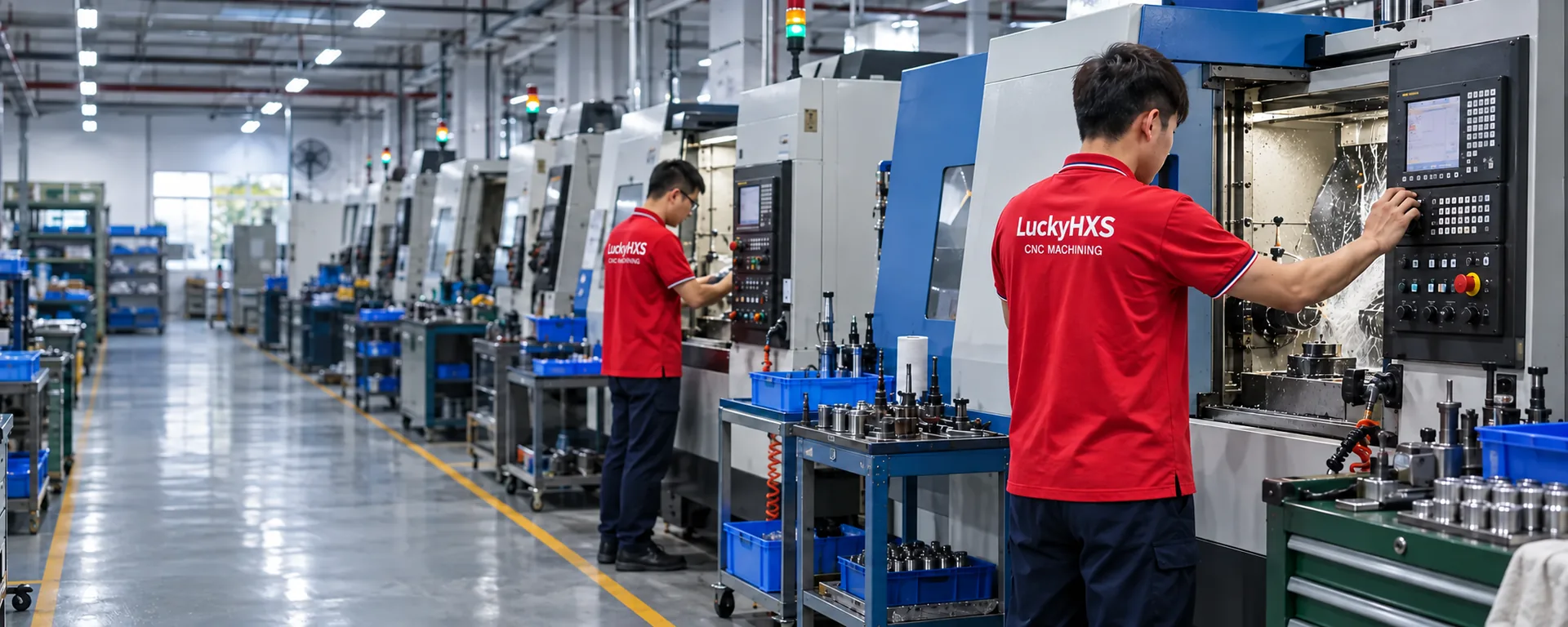
An approved sample is valuable only when its drawing revision, program, setup, tooling and inspection requirements can be transferred into repeat production.
RFQ and Drawing Review
Confirm the latest drawing revision, CAD model, material, quantity, finishing and functional requirements.
Process and Datum Planning
Select the machining route, workholding references and critical feature relationships.
Material Confirmation
Confirm the required grade and relevant material condition before machining.
Programming and Setup
Prepare toolpaths and workholding around access, rigidity and related features.
First Article Verification
Measure the agreed critical dimensions and functional relationships before continuing.
In-Process Control
Monitor features affected by tool wear, setup condition, burr formation or material behavior.
Finishing and Final Verification
Review post-finish dimensions, appearance and protected interfaces where required.
Repeat-Order Control
Use the approved revision and retained production requirements as the reference for future orders.
Prototype approval does not automatically create repeatability. The production route and inspection method must preserve the approved requirement.
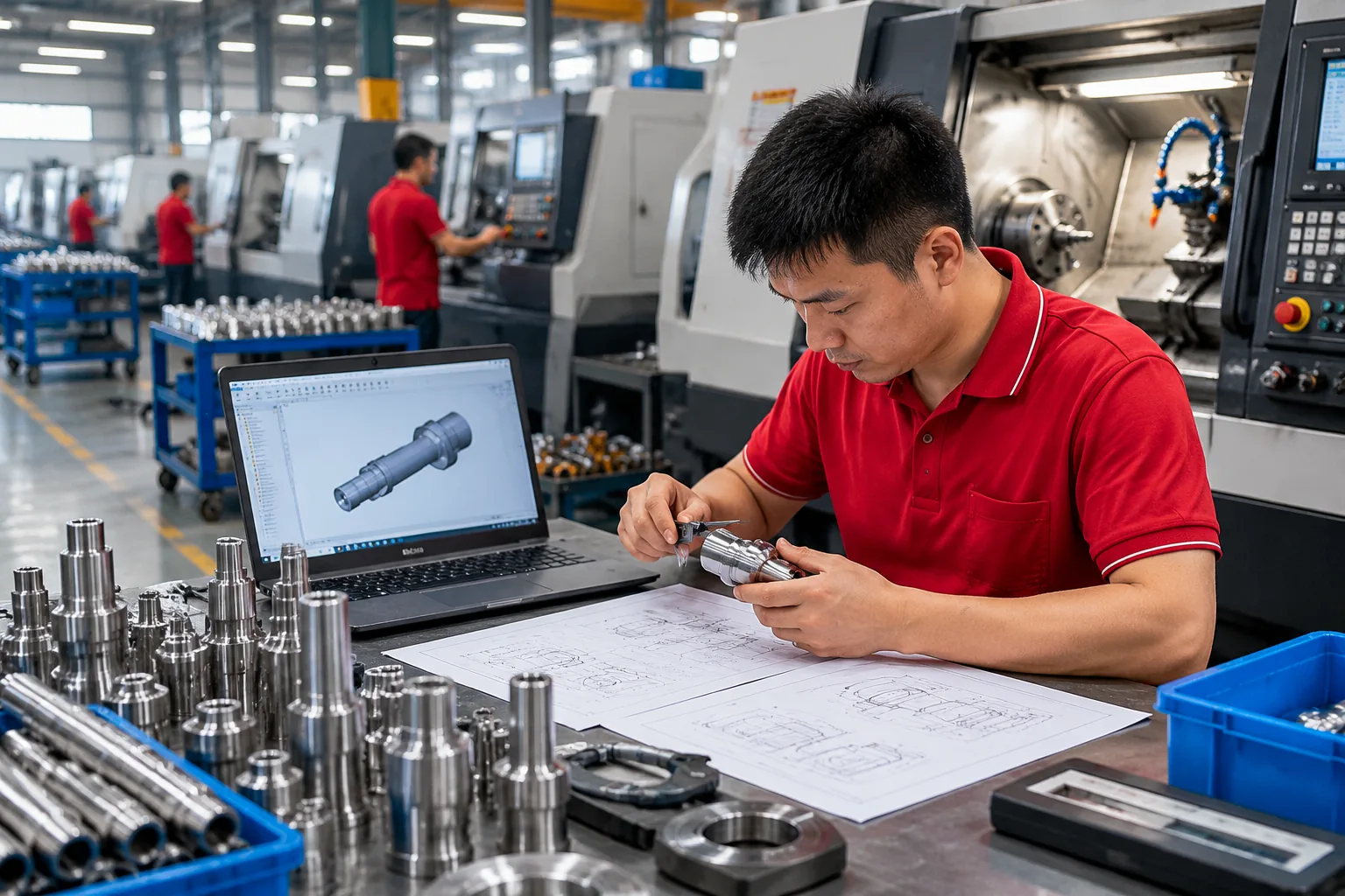
Why Source Custom CNC Milling Parts From LuckyHXS?
Geometry-Led Process Selection
The machining route is evaluated from the actual part geometry, tool access and critical relationships rather than forcing every drawing into the same setup.
Functional Datum Review
Related holes, bores, pockets, faces and interfaces are considered together when they control assembly.
Metal and Engineering-Plastic Options
Available material directions include aluminum, stainless steel, brass, copper, free-machining steel and selected engineering plastics.
Finishing Coordination
Machining dimensions can be reviewed together with anodizing, plating, sandblasting, polishing and other suitable finishing requirements.
Feature-Based Inspection
Measurement methods are selected around the feature being verified, including size, position, flatness, thread fit, runout and internal burr control.
Prototype to Repeat-Order Support
LuckyHXS supports drawing-based sample development and repeat manufacturing while keeping revision and critical-feature requirements visible in the production plan.
A useful quotation should reflect how the part will be manufactured and verified—not only a machine rate.
Selected CNC Milling Project Examples
These anonymized examples show how material, geometry and assembly requirements can change the manufacturing plan. Customer identities and confidential drawing details are not disclosed.
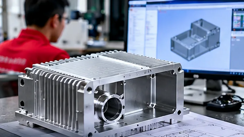
Aluminum 7075 Sensor Enclosure
Project focus: internal cavity, multi-face mounting features and controlled relationships between the enclosure datum and sensor interface.
Manufacturing response: review tool access, workholding sequence and related features before selecting the multi-face machining route.
Buyer value: the process plan is built around final alignment rather than treating each surface as an isolated dimension.
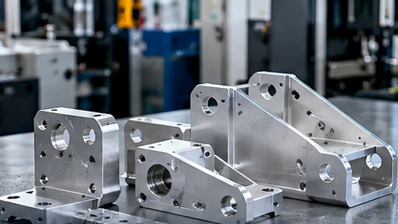
Aluminum 6061 EV Control Bracket
Project focus: mounting-hole pattern, structural rigidity and final fit after surface treatment.
Manufacturing response: use the primary installation datum to control the related holes and review finishing allowance on mating features.
Buyer value: hole position, mounting surfaces and post-finish assembly conditions are evaluated together.
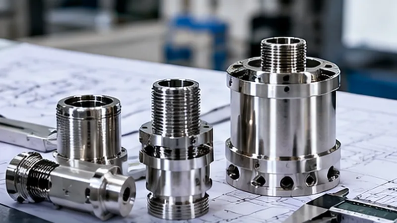
Stainless Steel 316L Sensor Housing
Project focus: internal features, thread quality, corrosion-resistant material and clean functional surfaces.
Manufacturing response: coordinate tool access, burr control, thread inspection and the final application requirements.
Buyer value: material choice and inspection planning remain connected to the housing’s functional interfaces.
CNC Milled Components for Precision Assemblies
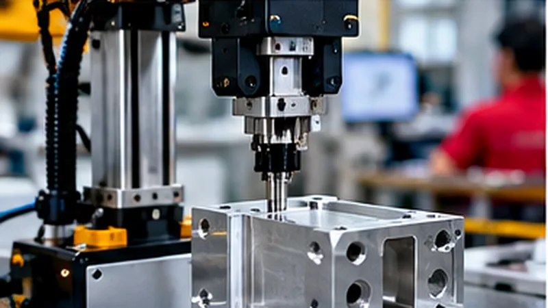
Robotics and Automation
Typical parts: brackets, gripper blocks, sensor mounts, fixtures and structural components.
Key concerns: datum repeatability, hole position and assembly access.
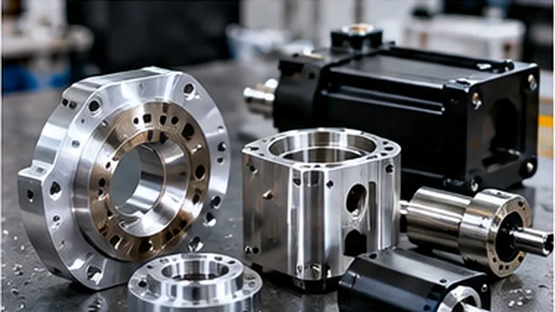
Motors and Motion Systems
Typical parts: motor mounts, bearing supports, adapter plates and precision bases.
Key concerns: bore alignment, mounting-face relationship and vibration-sensitive fit.
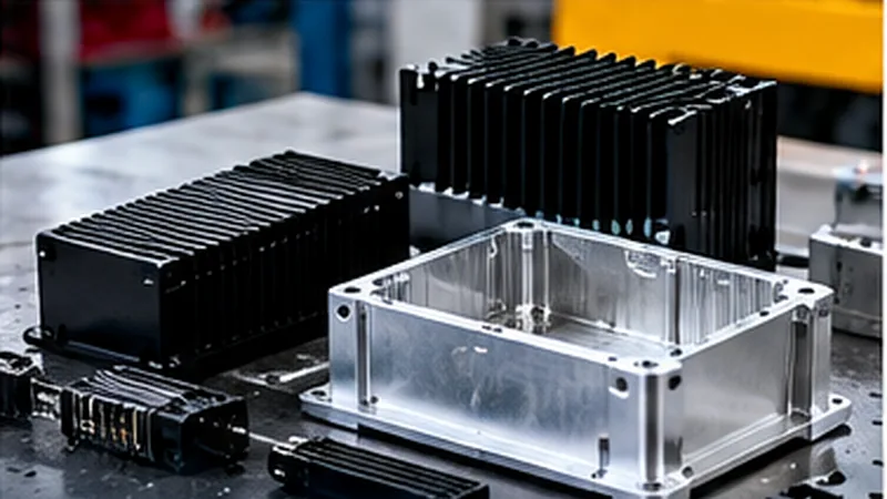
Electronics and Communication Equipment
Typical parts: enclosures, heat sinks, control housings and connector panels.
Key concerns: cavity geometry, connector position, thermal contact and finishing.
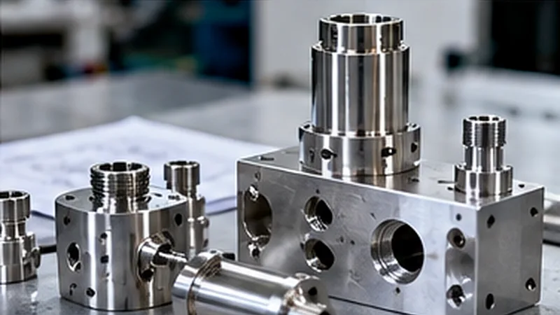
Fluid-Control Equipment
Typical parts: manifolds, valve blocks, ported plates and cooling components.
Key concerns: sealing faces, port intersections, threads, burrs and cleanliness.
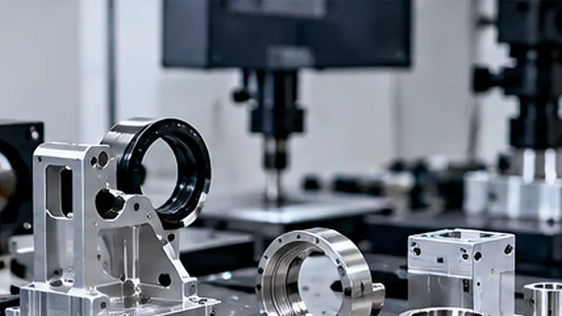
Sensors and Precision Instruments
Typical parts: sensor housings, camera mounts, optical supports and instrument brackets.
Key concerns: alignment, angular relationship and stable mounting interfaces.
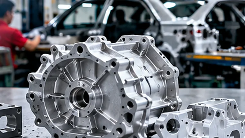
Automotive and Electric-Vehicle Equipment
Typical parts: control brackets, mounting plates, thermal parts and equipment housings.
Key concerns: assembly repeatability, finishing and production consistency.
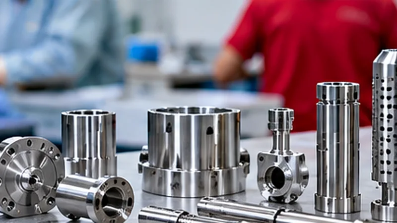
Medical-Equipment Components
Typical parts: instrument housings, sensor mounts and equipment interfaces.
Key concerns: drawing-defined features, material requirements, surface condition and documentation needs. Final regulatory suitability remains the customer’s responsibility.
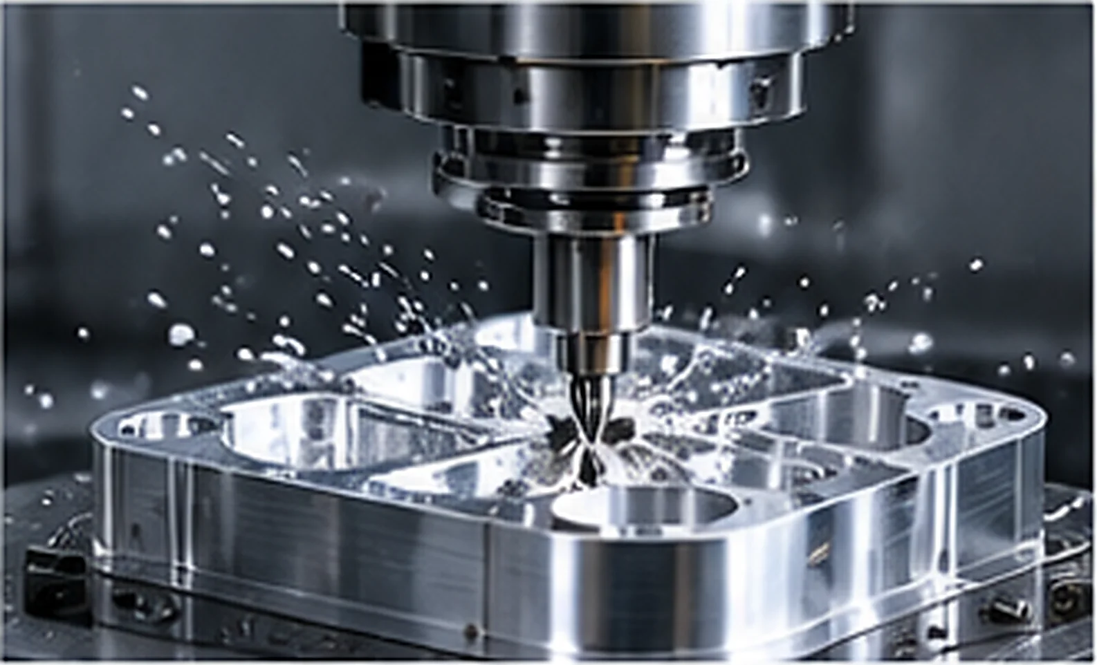
Industrial Machinery
Typical parts: bases, fixtures, tooling components, covers and structural mounts.
Key concerns: rigidity, service access, hole patterns and mating surfaces.
What Drives the Cost of a CNC Milled Part?
There is no universal price for a made-to-drawing component. A quotation reflects the manufacturing and verification effort required for the specific part.
Material
Raw-stock cost, grade, condition, availability and machinability affect the starting cost.
Geometry
Deep pockets, thin walls, small internal radii and complex surfaces can increase tool reach and machining time.
Setup Count
Features on several faces may require additional workholding, programming and datum transfer.
Tolerance
Tighter requirements can require slower machining, controlled environments or more detailed inspection.
Quantity
Programming and fixture costs are distributed differently between prototypes and repeat production.
Surface Finish
Anodizing, plating, sandblasting, polishing, masking and post-finish inspection add separate process requirements.
Inspection & Packaging
Complex datum structures, CMM programs, dedicated gauges, detailed documentation, and shipping preparation affect the final project plan.
Cost reduction should remove unnecessary manufacturing effort without weakening the features that control function.
How to Compare CNC Milling Parts Manufacturers
A useful supplier comparison should examine how each manufacturer converts the drawing into a repeatable machining and inspection plan. Machine lists and low hourly rates do not provide the complete answer.
-
1
Ask How the Supplier Interprets Functional Datums The supplier should be able to explain which surfaces locate the part and how related features will be controlled.
-
2
Review the Proposed Machining Route Check whether the setup plan fits the geometry, tool access and critical relationships instead of relying on a generic process label.
-
3
Confirm Material and Finish Coordination The material grade, condition, coating allowance, masking and final inspection state should be clear.
-
4
Match Inspection to the Feature Ask how hole position, flatness, thread fit, runout, sealing faces and internal burrs will be verified.
-
5
Check Drawing-Revision Control The quotation, CAD model, inspection criteria and production program should reference the same approved revision.
-
6
Evaluate Repeat-Production Planning A supplier should explain how the approved sample requirement will be transferred to later batches.
-
7
Compare Total Project Risk, Not Only Unit Price Extra setups, rejected assemblies, rework, finishing damage and delayed validation can cost more than a small difference in machining price.
The right manufacturer should make the production logic understandable before the order moves forward.
What to Include in a CNC Milling RFQ
A complete RFQ reduces assumptions and helps the manufacturer evaluate process, cost and inspection requirements more accurately.
Drawing and Model
- Latest 2D drawing with revision
- 3D CAD model where available
- Units, general tolerances and GD&T
- Threads, fits and critical-to-quality features
Material and Finish
- Material family and exact grade
- Required material condition where relevant
- Surface finish, color and masking requirements
- Dimensions that apply after finishing
Quantity and Production Stage
- Prototype or sample quantity
- Expected repeat-order quantity
- Any planned volume changes
- Target schedule for review
Inspection and Application
- Functional datums and mating features
- Required inspection records
- Assembly or operating conditions that affect the part
- Packaging requirements for protected surfaces
If a requirement is still undecided, identify it clearly so it can be reviewed before quotation rather than assumed during production.
CNC Milling Parts Buyer Guide
What types of CNC milling parts can LuckyHXS manufacture?
LuckyHXS manufactures made-to-drawing housings, enclosures, brackets, mounting plates, adapter plates, precision bases, manifold blocks, heat sinks, fixtures, motor mounts, sensor mounts and complex multi-sided components. The final process depends on geometry, material, tolerance, quantity and inspection requirements.
What is the difference between 3-axis, 4-axis and 5-axis milling?
Three-axis milling is suitable when the main features can be reached from standard directions. Rotary or four-axis positioning can help with features around a part. Five-axis machining may be evaluated for compound angles and related features across several faces. More axes are useful only when they reduce setup risk or improve access for the specific geometry.
What tolerances can be achieved on CNC milled parts?
A standard machining tolerance around ±0.01 mm may be reviewed for suitable features. Actual capability depends on material, geometry, wall thickness, feature size, setup, finishing and inspection method. Tighter critical features require drawing review before they are accepted.
Which materials are suitable for CNC milling?
Common options include aluminum, stainless steel, brass, copper, free-machining steel and engineering plastics such as POM, PTFE and Nylon. Select the material from the required strength, weight, corrosion resistance, thermal behavior, electrical properties, wear conditions and surface finish.
How are thin-wall parts and deep pockets handled?
Thin walls require careful workholding, cutting sequence and material-removal planning. Deep pockets require realistic tool reach and internal corner radii. Where the design permits, increasing wall thickness, reducing pocket depth or adding a larger internal radius can reduce manufacturing risk.
How should critical hole patterns be specified?
Identify the functional datum, mating component and positional relationship rather than specifying only individual hole diameters. Dowel holes, mounting holes and cross-face patterns may require coordinate or functional inspection.
Can one supplier support both prototypes and repeat production?
Yes, when the approved drawing revision, process route, setup, tooling and inspection criteria are transferred into the production plan. A successful prototype alone does not guarantee that later batches will repeat the same functional requirement.
What information is needed for a CNC milling quotation?
Provide the latest drawing, 3D model where available, material and grade, quantities, critical tolerances, threads and fits, surface finish, inspection requirements and expected schedule. Highlight any mating features or post-finish dimensions that control assembly.
Quality and Manufacturing You Can Review
LuckyHXS manufactures custom components from customer drawings in Shenzhen. Supplier confidence begins with a clear connection between the approved drawing, material, machining route, critical features and inspection method.
Manufacturing Review
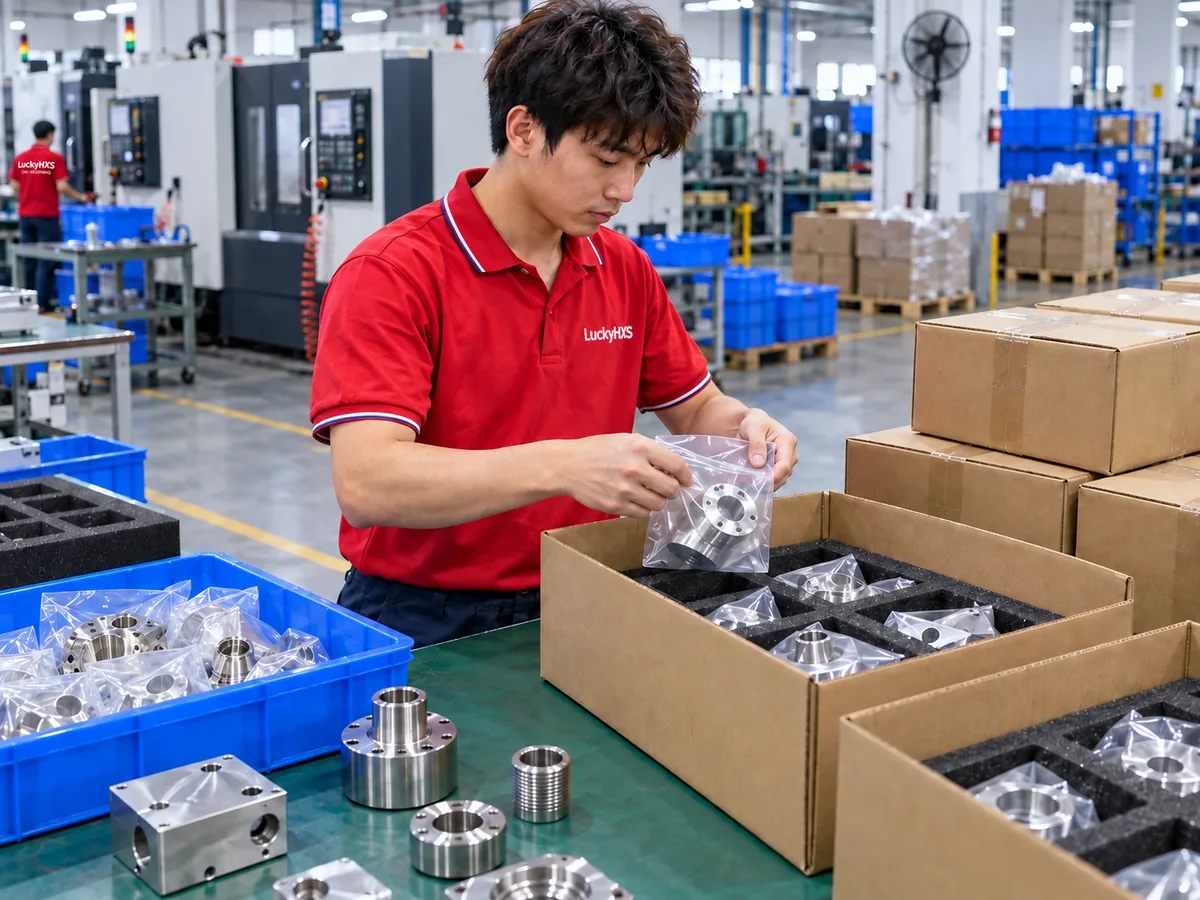
Part geometry, workholding, tool access and critical relationships are considered before the production route is confirmed.
In-Process Attention
Features affected by tool wear, distortion, burr formation or setup condition can be checked during manufacturing rather than only after finishing.
Functional Inspection
The measuring method is selected according to the feature being verified, including size, position, flatness, thread fit, runout and internal cleanliness.
Project Communication
Drawing revision, finishing requirements, quantity and inspection expectations should remain visible from quotation through production.
Ask for a production and inspection discussion based on your actual drawing rather than relying on generic capability statements.
Related CNC Machining Capabilities
Explore CNC Milling Services
Review milling processes, engineering considerations and service scope for drawing-based parts.
Compare Custom CNC Machining Services
Compare milling, turning, Swiss machining and turn-mill routes for different component geometries.
View CNC Turning Parts
For shafts, bushings, pins and other components dominated by rotational geometry.
Explore Stainless Steel CNC Parts
Review stainless-steel material choices and machining considerations for custom components.
Explore Plastic CNC Machined Parts
Review POM, PTFE, Nylon and other selected engineering-plastic machining options.
About LuckyHXS
Learn more about the company, manufacturing approach and available project support.
Request a CNC Milling Parts Review
Send your latest drawing, material, quantities, finishing requirements and critical features. We will use the information to discuss the suitable machining route, inspection focus and quotation scope for your custom component.
Tell Us About Your Part