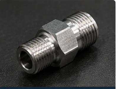
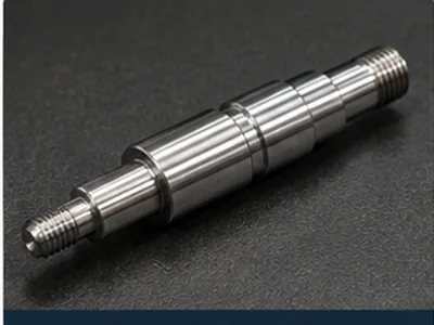
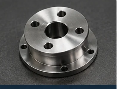
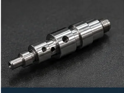
Made to Your Drawing Precision CNC Turning OD / ID Relationship Review

Custom CNC Lathe Machining for Precision Turned Parts

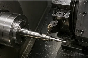
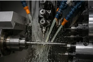
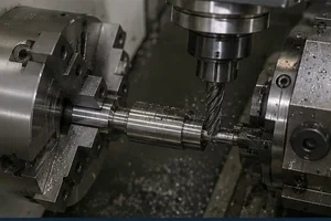
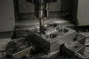
LuckyHxs manufactures custom CNC turned components directly from customer drawings, including shafts, pins, bushings, sleeves, threaded parts, fittings, flanges and other rotational components. Our machining review focuses on OD/ID relationships, common rotational datums, shoulders, bores, threads, functional surfaces and repeat-batch consistency—not only individual dimensions.

20+ Years

CNC Experience

153

Precision Machines

±0.01 mm

Standard Tolerance

1 to 100k+

Prototype to Batch

Request CNC Turning Quote

Ask Which Turning Process Fits Your Part

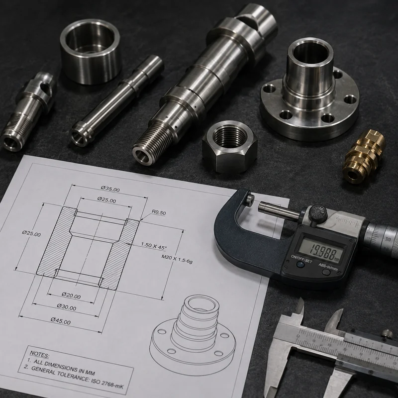
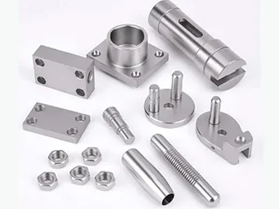
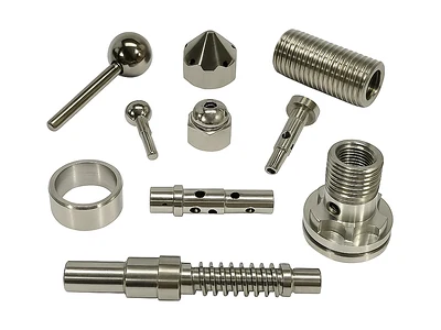
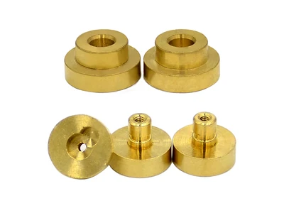
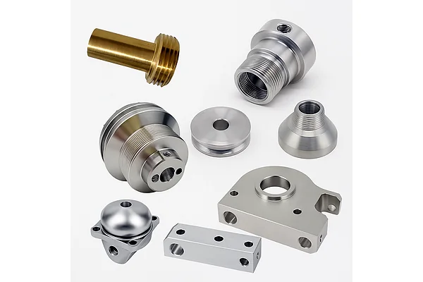
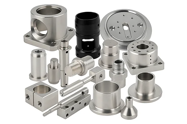
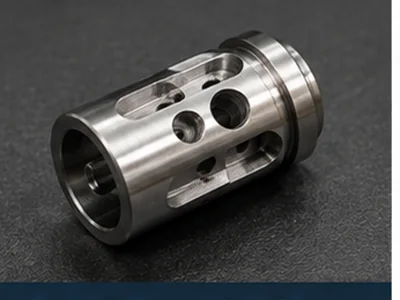
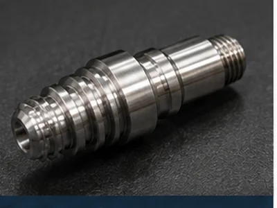
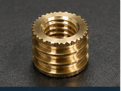
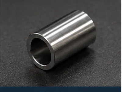
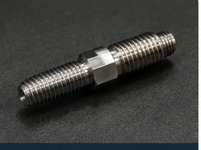
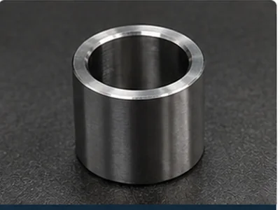
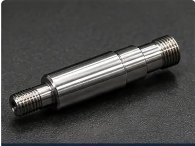
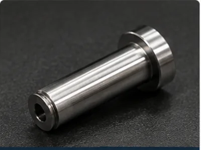
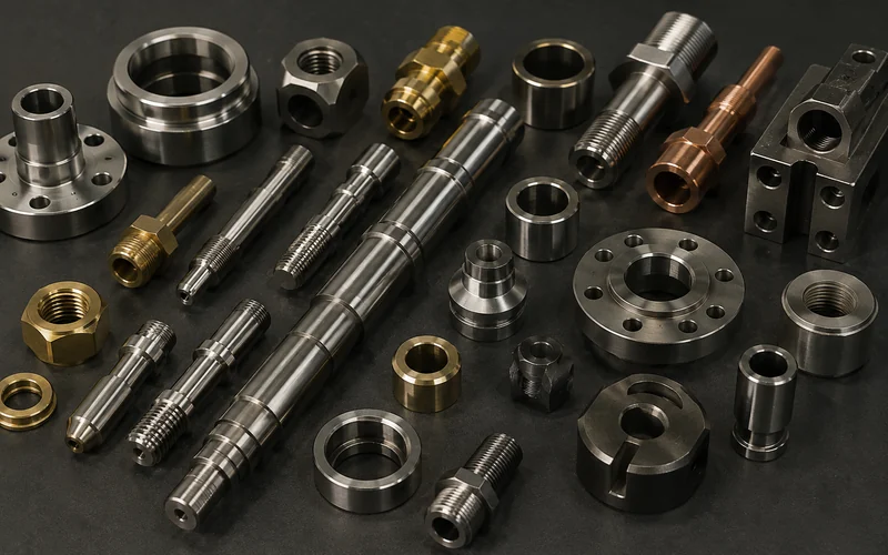
Collection of custom CNC turned components including shafts, bushings, pins, and threaded parts

CNC Lathe Machining at a Glance

Supply Type
Custom Made-to-Drawing CNC Turned Components
Typical Parts
Shafts / Pins / Bushings / Sleeves / Threaded Parts / Fittings / Flanges / Valve Components
Core Operations
Turning / Facing / Boring / Grooving / Threading / Taper Turning / Parting
Materials
Aluminum / Stainless / Brass / Copper / Free-Machining Steel / Titanium / Selected Plastics
Standard Tolerance Reference
±0.01 mm
Critical Features
OD / ID / Bore / Runout / Shoulder / Groove / Thread / Face
Drawing Inputs
PDF, STEP, STP, IGES, DWG, DXF

Buyer Fit: Is CNC Lathe Right for Your Part?

Does your part primarily revolve around a central axis and contain critical diameters, bores, shoulders or threads? It may be a strong candidate for CNC lathe machining.

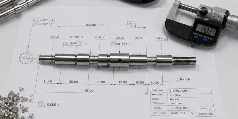
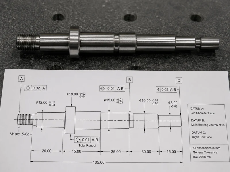
Engineering drawing next to a precision stepped shaft and micrometer

CNC Lathe Machining Means Custom Turned Parts—not Machine Spare Parts

We manufacture the parts produced by CNC lathes—not replacement components for the lathe machine itself.

Are You Searching For:

CNC Lathe Machine Parts?

  • Headstock / Spindle
  • Chuck / Bed
  • Tailstock / Turret / Control
This is not LuckyHxs' main product scope.
Our Core Business

Or Do You Need:

Custom CNC Turned Parts?

  • Shaft / Pin / Bushing
  • Sleeve / Insert / Fitting
  • Flange / Nozzle
This is LuckyHxs' manufacturing scope.
Round Base + Cross Holes/Flats → Turn-Mill Review
Small + Slender → Swiss Review
Prismatic Part → CNC Milling Review

Custom CNC Lathe Parts We Manufacture to Your Drawings

Precision rotational components manufactured to exact customer specifications for OEM assemblies.

CNC Lathe Shafts & Stepped Rotational Parts

CNC Lathe Shafts & Stepped Rotational Parts

Precision shafts, stepped shafts, motor shafts, and short spindles requiring concentric relationships across multiple diameters.

Features: OD, Multiple Diameters, Shoulder, Groove, Thread
Watch Point: Common Axis, Runout, Shoulder Position
CNC Turned Pins, Studs & Locating Components

CNC Turned Pins, Studs & Locating Components

Precision locating pins, guide pins, shoulder pins, and studs where diameter and shoulder position control functional fit.

Features: Precision OD, Shoulder, Thread, Retaining Feature
Watch Point: OD Tolerance, Functional Length, Mating Fit
CNC Turned Bushings, Sleeves & Spacers

CNC Turned Bushings, Sleeves & Spacers

Guide bushings, flanged bushings, and thin-wall sleeves requiring strict ID/OD concentricity and wall thickness control.

Features: ID, OD, Flange, Bore, Thin Wall
Watch Point: Bore-to-OD Relationship, Roundness
Threaded Parts, Inserts & Custom Fasteners

Threaded Parts, Inserts & Custom Fasteners

Threaded inserts, precision studs, special nuts, and standoffs requiring specific thread fits and entry/exit control.

Features: External/Internal Thread, Shoulder, Knurl
Watch Point: Effective Thread Length, Thread-to-OD
Fittings, Adapters & Cylindrical Connectors

Fittings, Adapters & Cylindrical Connectors

Straight adapters, connector bodies, and couplings focusing on thread-to-bore relationships and seating faces.

Features: Internal/External Thread, Bore, Seating Face
Watch Point: Thread-to-Bore Relationship, Shoulder Position
Flanges, Hubs, Rings & Round Interface Components

Flanges, Hubs, Rings & Round Interface Components

Precision flanges, coupling hubs, and spacer rings where face runout and pilot bore relationships are critical.

Features: Face, Pilot Bore, OD, ID, Thickness
Watch Point: Face Runout, Face-to-Bore Relationship
Valve Stems, Nozzles & Cylindrical Fluid-Control Parts

Valve Stems, Nozzles & Cylindrical Fluid-Control Parts

Precision stems, needles, and orifice bodies requiring strict control over tapers, sealing interfaces, and straightness.

Features: Small OD, Taper, Sealing Interface, Precision Stem
Watch Point: Concentricity, Straightness, Seat Relationship
Custom Multi-Diameter & Precision Lathe Components

Custom Multi-Diameter & Precision Lathe Components

Complex rotational parts combining multiple ODs, IDs, threads, and grooves into a single continuous functional geometry.

Features: Multiple ODs/IDs, Shoulder Stack, Internal/External Thread
Watch Point: Continuous Rotational Geometry, Common Axis

Precision Turned Components for Different Rotational Functions

Different products use different features, but CNC lathe performance is ultimately built around stable rotational geometry.

ROTATE → Shaft
LOCATE → Pin
GUIDE → Bushing
SPACE → Spacer
FASTEN → Threaded Part
CONNECT → Fitting
CENTER → Flange / Hub
CONTROL → Valve Stem / Nozzle
Precision CNC turned shaft Stepped motor shaft Precision guide bushing Thin-wall sleeve Locating shoulder pin Threaded brass insert Precision threaded stud Straight fluid fitting Round adapter flange Precision valve stem Complex multi-step turned component Custom bore-intensive lathe part

Materials for Custom CNC Lathe Machining

Material should be selected according to function, environment, machinability, surface treatment and drawing requirements.

ALUMINUM

6061, 6063, 6082, 7075

Typical: Lightweight Shafts, Adapters, Housings, Spacers

Watch Point: Thin Wall Distortion, Surface Finish, Anodizing Fit Changes, Thread Fit

STAINLESS STEEL

303, 304, 316, 316L

Typical: Shafts, Valve Components, Fittings, Precision Sleeves

Watch Point: Tool Wear, Cutting Heat, Surface Hardening, Thread Quality, Burr Control

BRASS

H57, H59, H62, C3604

Typical: Inserts, Fittings, Connectors, Bushings, Threaded Components

Watch Point: Excellent machinability, ideal for complex internal threads and fine features.

FREE-MACHINING STEEL

1214, 1215

Typical: Shafts, Pins, Studs, Bushings, High-repeat turned components

Watch Point: Surface protection (plating/coating) required after machining.

OTHER MATERIALS

COPPER

Selected electrical and connector components according to project.

TITANIUM

Project-specific high-strength, lightweight rotational components.

ENGINEERING PLASTICS

POM, Nylon, PTFE, ABS where suitable for non-metal applications.

Choose the Process Around Part Geometry—Not the Process Name

CNC lathe machining is usually most efficient when the part's functional geometry is primarily rotational. Each operation must be evaluated as part of the same functional geometry.

Core CNC Lathe Operations for Rotational Parts

OD TURNING

Produces: External Diameter
Risk: Diameter Drift / Taper

ID TURNING / BORING

Produces: Precision Bore
Risk: Taper / Chatter / Bore Drift

FACING

Produces: End Face
Risk: Face Runout / Center Mark

GROOVING

Produces: Retaining / Seal Groove
Risk: Position / Burr

THREADING

Produces: Internal / External Thread
Risk: Entry / Engagement / Burr

TAPER TURNING

Produces: Conical Geometry
Risk: Angle / Surface

CNC Lathe, Swiss, Turn-Mill or Milling—Which Process Fits?

Current Page

STANDARD CNC LATHE

Best Fit: Primarily Cylindrical, Standard Diameter

Typical: Shafts, Bushings, Sleeves, Fittings, Flanges

Standard CNC lathe part

SWISS CNC MACHINING

Best Fit: Small Diameter, Long / Slender, Feature Dense

Typical: Small Shafts, Connector Pins, Miniature Pins

Swiss machined slender part

TURN-MILL

Best Fit: Round Base + Significant Off-Axis Features

Typical: Ported Sleeve, Cross-Drilled Fitting

Turn-mill part with cross holes

CNC MILLING

Best Fit: Prismatic, Block, Plate, Housing, Pocket

Typical: Brackets, Enclosures, Fixtures

CNC milled prismatic block

Why CNC Lathe Parts Fail Even When Individual Dimensions Pass

A CNC lathe part should be inspected as one continuous rotational geometry—not as a collection of independent diameters.

#1

OD & ID Dimensions Pass, but the Common Rotational Axis Drifts

Individual Diameters PASS ≠ Complete Rotational Geometry PASS. The rotating assembly wobbles or mating bore runs eccentrically.

Focus: Runout & Concentric Relationship

#2

Second-Operation Re-Chucking Shifts the Rotational Datum

Re-Chucking Is Not Just Another Operation—it Is Another Datum-Control Risk. Two ends run differently.

Focus: Front-to-Rear Datum Transfer

#3

Prototype Passes, but Critical Turning Geometry Drifts in Production

Prototype Approval ≠ Automatic Repeat-Batch Turning Consistency. Tool wear and setup variation cause ODs and bores to slowly move.

Focus: In-Process Checks & Tool Condition

4. Diameters Pass, but Shoulders Lose Axial Relationship

Bearing does not seat; spacer stack changes.

5. Faces & Pilots Pass Size Checks but Runout Fails

Face wobble causes uneven contact on interface.

6. Deep Bores Pass at Entry but Drift Deeper Inside

Tool overhang causes taper or bell-mouth condition.

7. Thin-Wall Parts Distort After Chuck Release

Clamped geometry pass != free-state geometry pass.

8. Threads Pass Gauging but Fail Functional Assembly

Wrong shoulder distance or damaged first thread.

9. Surface Finish Numbers Pass, but Surface Fails

Ra passes, but chatter or parting marks remain.

10. Post-Processing Changes Critical Lathe Fits

Anodizing or plating alters final functional dimensions.

OD & ID Dimensions Pass, but the Common Rotational Axis Drifts

OD A: PASS

OD B: PASS

ID/Bore: PASS

Common Axis Relationship: FAIL

Runout / Functional Fit: FAIL

Individual Diameters PASS ≠ Complete Rotational Geometry PASS

Consequence: Rotating assembly wobbles, bearing fit becomes uneven, sleeve guidance changes, or mating bore runs eccentrically.

LuckyHxs Approach: We review the functional rotational datum, separate size tolerance from axis relationship, plan machining sequence around critical cylindrical features, and use inspection appropriate to runout requirements.

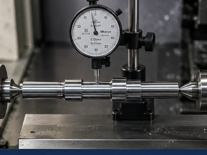
Stepped shaft showing OD and ID with an engineering centerline

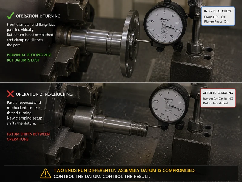
Front & Rear Features Pass Individually but Lose the Same Rotational Datum

Re-Chucking Is Not Just Another Operation—it Is Another Datum-Control Risk.

The Risk: Removing, reversing, and re-chucking a part transfers the datum. Jaw contact variation, clamping force, or a chip between surfaces can cause the newly established axis to shift.

Consequence: Two ends run differently, rear thread runs off front OD, flange face wobbles, or assembly axis shifts.

LuckyHxs Approach: We identify which first-operation feature becomes the next datum, protect critical clamping surfaces, select chuck/collet strategy according to geometry, and inspect final relationships from the drawing-defined datum.

Split view showing operation 1 turning, re-chucking process, and operation 2 turning

Prototype Passes, but Critical Turning Geometry Drifts in Production

Prototype Approval ≠ Automatic Repeat-Batch Turning Consistency

The Risk: In a prototype, a single part is carefully babied. In production, insert wear, boring tool wear, cutting heat, chip control, and setup variation cause dimensions to drift.

Consequence: OD slowly moves, bore size changes, shoulder position drifts, surface marks increase, or part-off burr increases.

LuckyHxs Approach: We implement First Article inspection, identify critical OD/ID features for in-process checks, monitor tool condition, and verify final batch consistency before shipment.

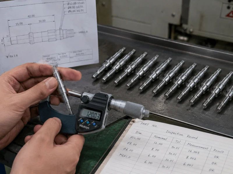
Micrometer measuring a turned component in foreground with a production batch in background
Real shaft with engineering centerline indicating OD, Bore, and Face datums

Rotational Parts Need a Functional Axis—not Just Correct Diameters

Do not treat diameter tolerance and rotational relationship as the same requirement.

  • SIZE Answers: Is the diameter correct?
  • DATUM Answers: What feature establishes the functional axis? (e.g., Bearing Journal, Precision Bore, Pilot Diameter)
  • RUNOUT Answers: How does the rotating surface behave relative to the datum?
  • BORE-TO-OD RELATIONSHIP Answers: Does the internal feature remain correctly related to the outside?

Correct Diameters Do Not Guarantee the Correct Shoulder Stack

Diameter PASS ≠ Axial Feature Stack PASS

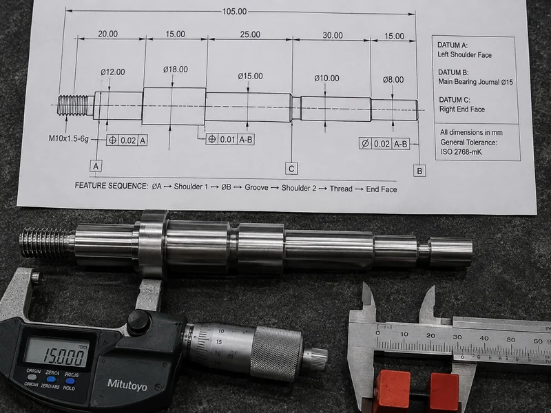
A typical stepped shaft involves a sequence: ØA → Shoulder 1 → ØB → Groove → Shoulder 2 → Thread → End Face. We must check:

  • Shoulder-to-Shoulder Distance
  • Face-to-Groove Position & Groove Width/Depth
  • Thread Start & Effective Thread Length
  • Overall Functional Length

Typical Failure: Bearing does not seat, retaining ring misses groove, seal position changes, or mating part bottoms early.

Macro view of a stepped shaft showing shoulder, groove, thread start, and end face

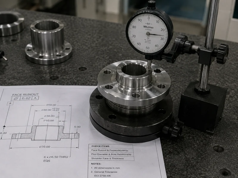
Face Dimension PASS Does Not Guarantee a Stable Rotating Interface

Face Dimension PASS ≠ Functional Face Runout PASS

Applicable to Flanges, Hubs, Rings, Shaft Shoulders, and Valve Interfaces. We check:

  • Face Runout & Perpendicularity
  • Pilot Diameter & Bore Relationship
  • Shoulder Face & Thickness

Core Logic: Pilot + Bore + Face Must Work as One Rotational Interface. A failure here causes face wobble, uneven contact, coupling misalignment, or rotational vibration.

Precision round flange being checked with a dial indicator for face runout

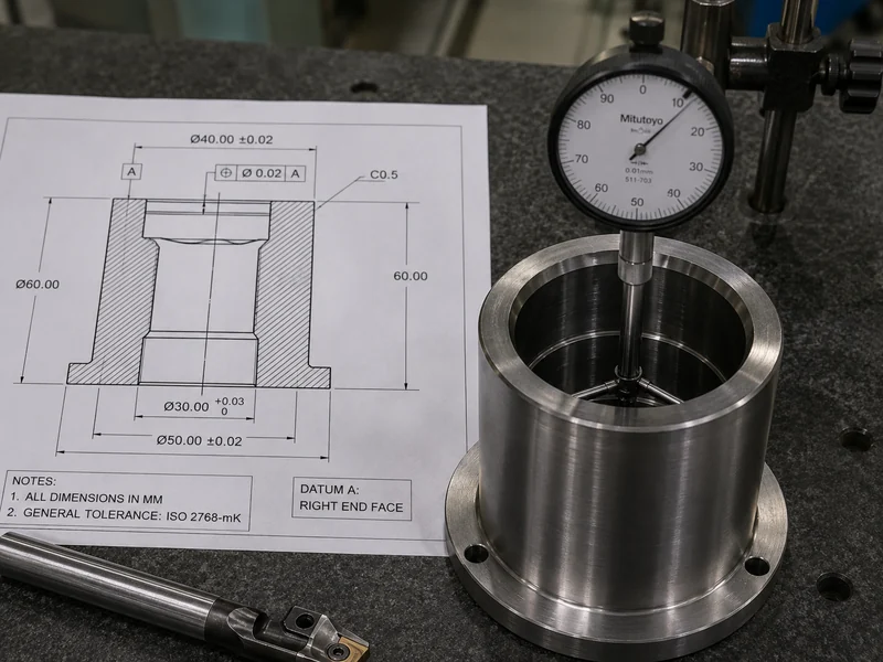
A Bore That Passes at the Entrance Can Still Drift Deeper Inside

Bore Diameter at the Entrance Does Not Define the Complete Deep Bore

Applicable to Deep-Bore Bushings, Sleeves, Fittings, and Cylindrical Housings. Risks include:

  • Tool Overhang causing Vibration and Chatter
  • Taper or Bell-Mouth Condition
  • Chip Evacuation issues damaging the Internal Surface

LuckyHxs Approach: We review tool accessibility, choose boring strategy based on geometry, plan chip evacuation, and review measurement access for the middle and deep bore—not just the entrance.

Cutaway view of a CNC sleeve showing entrance, deep hole, and boring bar

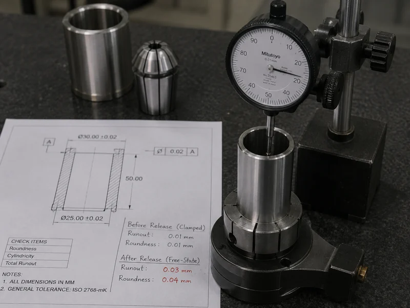
Clamped Geometry PASS Does Not Guarantee Free-State Rotational Geometry PASS

Clamped Geometry PASS ≠ Free-State Rotational Geometry PASS

Applicable to Thin-Wall Sleeves, Bushings, Spacer Rings, and Lightweight Round Components.

While Clamped: ID PASS, OD PASS, Roundness PASS.

After Release: Chuck/collet force and residual stress cause the bore to become oval, OD to shift, or wall thickness to vary.

LuckyHxs Approach: We control clamping force according to part geometry, plan rough/finish sequences, and check functional geometry after unclamping.

Thin-wall sleeve held in a collet and free-state inspection

The Part Still Has to Work After Threading, Surface Control & Finishing

A. THREAD INTERFACE

We check thread standard, pitch, class/fit, effective length, entry, relief, and thread-to-bore relationship.

Thread Gauge PASS ≠ Functional Thread Interface PASS

GO/NO-GO passes may still hide too short usable thread, damaged first thread, or wrong shoulder distance.

B. FUNCTIONAL SURFACE

We check bearing journals, guide surfaces, sleeve bores, and sealing interfaces.

Surface Finish Number PASS ≠ Functional Surface PASS

You cannot only look at the Ra number. Chatter, tool transition marks, nicks, and parting damage must be controlled.

C. POST-PROCESSING

Anodizing, Plating, Sandblasting, or Polishing according to material/project.

Machining Complete ≠ Final Functional Fit Complete

We must ask: Does the critical dimension apply before finishing or after finishing?

Control the Rotational Geometry From First Article to Final Batch

Inspection methods are selected according to drawing, geometry, tolerance and functional requirements.

12-Step Quality Flow

  1. RFQ / Drawing Review
  2. Drawing Revision Confirmation
  3. Material Confirmation
  4. Rotational Datum Identification
  5. Critical OD / ID Definition
  6. Process & Workholding Planning
  7. First Article Verification
  8. In-Process Dimension Checks
  9. Bore / Shoulder / Groove Review
  10. Thread / Surface / Burr Review
  11. Final Batch Verification
  12. Repeat-Order Requirement Retention

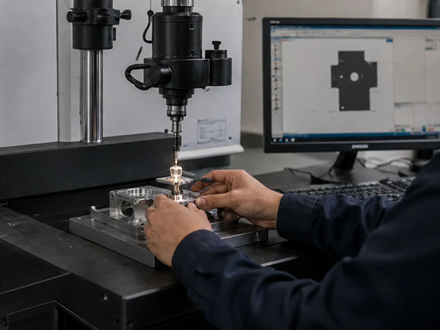
Inspection Methods: Micrometer, Caliper, Bore Gauge, Pin Gauge, Thread Gauge, Dial Indicator, CMM where suitable.

Applications

Motors & Motion Systems

Typical: Stepped Shaft
Watch: OD + Runout + Shoulder

Fluid-Control Equipment

Typical: Stem / Nozzle / Fitting
Watch: Bore + Thread + Surface

Robotics & Automation

Typical: Bushing / Pin / Sleeve
Watch: Concentricity + Fit

Electronics & Connectors

Typical: Adapter / Insert
Watch: Thread Engagement

Sensors & Instruments

Typical: Custom Housing / Flange
Watch: Face Runout + Bore

Industrial Equipment

Typical: Hub / Spacer
Watch: Thickness + Parallelism

A CNC Manufacturing Partner You Can Verify

Certificates & Compliance Documents

ISO9001
CE
REACH
ROHS
TEST REPORT

Customer Factory Visits

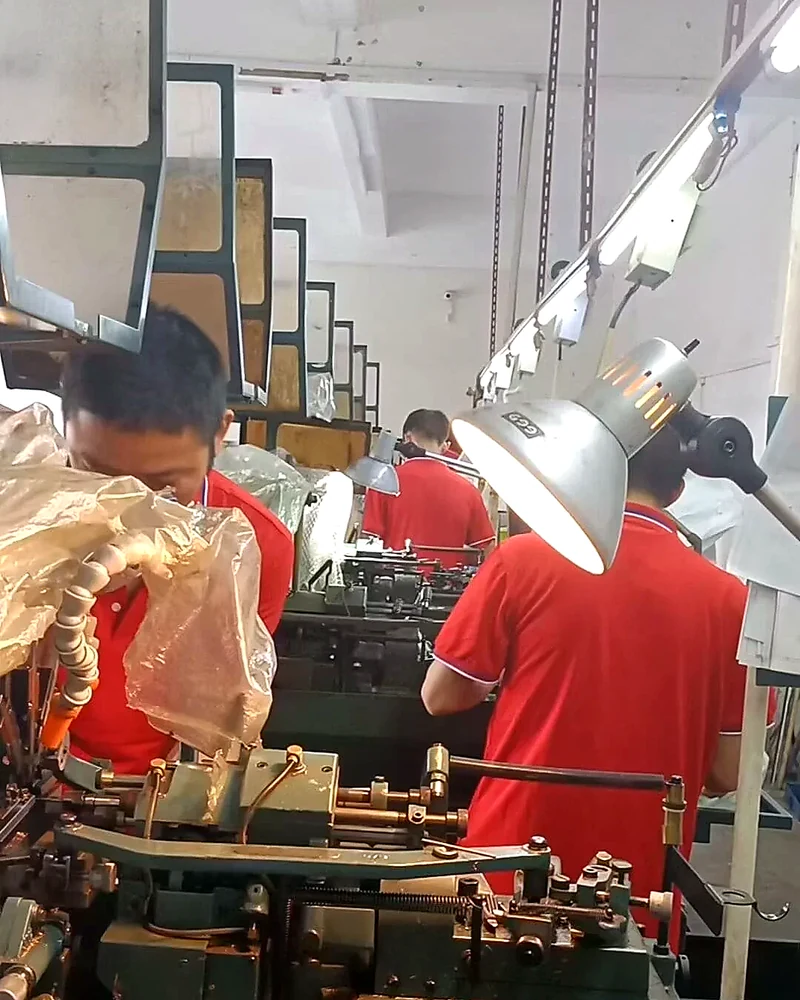
Factory Visit
Factory Visit
Production Review
Production Review
Technical Discussion
Quality Review
Quality Review

See How LuckyHxs CNC Parts Are Machined and Inspected

What Is a CNC Lathe and How Does CNC Lathe Machining Work?

A CNC lathe is a computer-controlled machine tool that rotates a workpiece around a central axis while cutting tools remove material to create cylindrical and rotational features.

How Does It Work?

  1. Raw material or a prepared blank is held in a chuck, collet or appropriate workholding system.
  2. The workpiece rotates around its spindle axis.
  3. The programmed cutting tool moves relative to the rotating workpiece.
  4. Turning produces outside diameters.
  5. Boring produces or finishes internal diameters.
  6. Facing controls end surfaces and overall length.
  7. Grooving, taper turning and threading add required rotational features.
  8. The finished component is inspected against the drawing.

What Does a CNC Lathe Produce?

Shafts, Pins, Bushings, Sleeves, Spacers, Threaded Parts, Fittings, Adapters, Flanges, Hubs, Valve Stems, Nozzles, and Custom Rotational Parts.

What Buyers Should Care About

Diameter, Bore, Common Axis, Runout, Shoulder Position, Thread, Surface, and Repeatability.

For a buyer, the important question is not how many machine parts a lathe contains (Spindle, Chuck, Turret, Control)—it is whether the supplier can control the rotational features that determine final assembly.
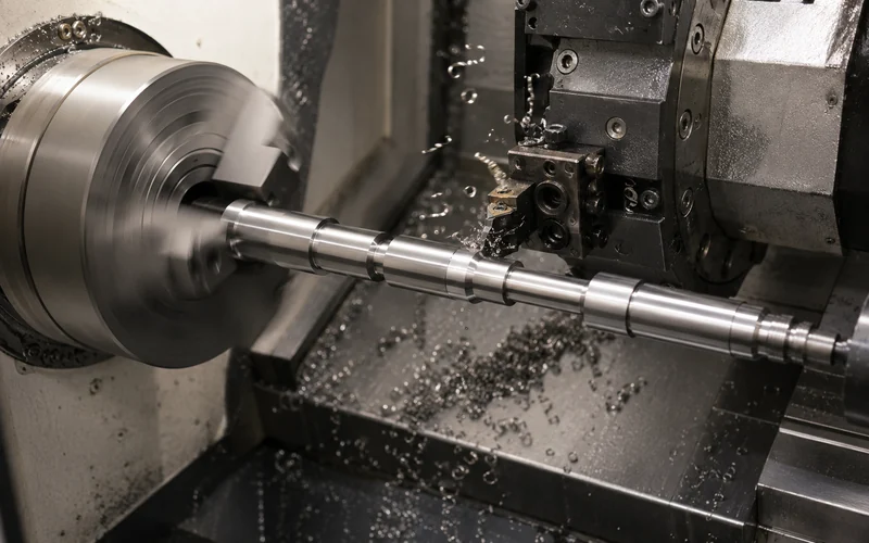
Inside a CNC lathe showing rotating cylindrical workpiece and cutting tool producing a finished shaft

What Can You Make With a CNC Lathe? Parts, Operations & Applications

CNC lathes are best suited to components whose functional geometry is primarily round, cylindrical or rotational.

What Can a CNC Lathe Make?

  • ✓ Shafts
  • ✓ Pins
  • ✓ Bushings
  • ✓ Sleeves
  • ✓ Spacers
  • ✓ Threaded Inserts
  • ✓ Studs
  • ✓ Fittings
  • ✓ Adapters
  • ✓ Flanges
  • ✓ Hubs
  • ✓ Valve Stems & Nozzles

Feature → Operation Mapping

  • OD → Turning
  • ID → Boring
  • End Face → Facing
  • Thread → Thread Turning
  • Groove → Grooving
  • Taper → Taper Turning
  • Cutoff → Parting

Where Standard CNC Lathe Machining Has Limits

A CNC lathe is highly efficient when the part geometry matches the process. It becomes inefficient when the design is dominated by features that belong to another machining route. Not ideal for:

  • Large Rectangular Blocks
  • Deep Prismatic Pockets
  • Complex Brackets & Multi-Surface Housings
  • Parts Dominated by Hole Patterns
  • Parts With Many Cross Holes / Slots / Flats
Collection of 8 typical CNC turned parts including stepped shaft, pin, bushing, sleeve, insert, fitting, flange, nozzle

CNC Lathe vs CNC Mill: Which Process Fits Your Part?

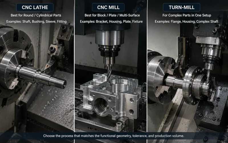
A CNC lathe and CNC mill remove material in different ways. The best process is the one that matches the functional geometry.

CNC LATHE

Motion: Workpiece Rotates

Geometry: Round / Cylindrical

Features: OD/ID/Bore/Thread/Groove

Concern: Common Axis / Runout

CNC MILL

Motion: Cutting Tool Rotates

Geometry: Block / Plate / Multi-Surface

Features: Pocket/Slot/Hole Pattern

Concern: Datum / Position / Flatness

When to Choose Turn-Mill

Round part + Flat, Cross Hole, Slot, Radial Port, or Side Thread.

When to Consider Swiss

Small diameter, long/slender, fine feature density, repeat production.

Can a CNC mill replace a lathe?

A mill can machine circular geometry, but that does not make it the best process for every cylindrical part. Likewise, a lathe cannot efficiently replace milling for primarily prismatic geometry.

Comparison showing a CNC lathe part, a CNC milled part, and a hybrid turn-mill example

Frequently Asked Questions About CNC Lathe Machining

What is a CNC lathe?
A computer-controlled machine tool that rotates a workpiece around a central axis while cutting tools remove material to create cylindrical and rotational features.
What does a CNC lathe machine do?
It produces precision outside diameters (turning), internal diameters (boring), end faces, grooves, threads, and tapers on primarily round components.
What can you make with a CNC lathe?
Common parts include shafts, pins, bushings, sleeves, spacers, threaded inserts, studs, fittings, adapters, flanges, hubs, valve stems, and nozzles.
What is the difference between CNC lathe machining and CNC turning?
They normally describe the same core turning process from different perspectives. "CNC lathe" refers to the machine/tool category. "CNC turning" refers to the machining process.
What is the difference between a CNC lathe and CNC mill?
In a CNC lathe, the workpiece rotates while the tool is stationary (best for round parts). In a CNC mill, the cutting tool rotates while the workpiece is stationary (best for block/plate parts).
Can a CNC mill replace a lathe?
Not generally. A mill can produce circular features, but primarily rotational parts are usually better evaluated for turning for efficiency and concentricity control.
What materials can LuckyHxs machine on CNC lathes?
Aluminum (6061, 7075), Stainless Steel (303, 304, 316), Brass (H59, C3604), Copper, Free-Machining Steel, Titanium, and selected engineering plastics (POM, PTFE).
What tolerances can LuckyHxs support?
Standard machining tolerance reference is ±0.01 mm. Actual feature capability depends on diameter, part length, material, bore depth, wall thickness, datum, and inspection method.
Can LuckyHxs manufacture both prototypes and repeat production?
Yes. Manufacturing and inspection planning are confirmed according to drawing, quantity and project requirements to ensure batch consistency.
What information should I send for a CNC lathe machining quote?
2D Drawing, 3D CAD, Material, Quantity, Critical OD/ID, Runout, Shoulder/Groove Dimensions, Threads, Surface Finish, Post-Processing, and Inspection Requirements.

Need a Turned Part Whose Complete Rotational Geometry Fits the Assembly?

Send your 2D/3D drawing, material, quantity, critical OD/ID dimensions, rotational datums, bores, shoulders, grooves, threads, surface finish and inspection requirements. LuckyHxs will review the part geometry and recommend CNC lathe machining, Swiss machining, turn-mill or another suitable manufacturing route before quotation.

Request Quote via WhatsApp

Email: admin1@lucky-hxs.com | Phone: +86 13342931453

Address: Shenzhen Bao'an Songgang