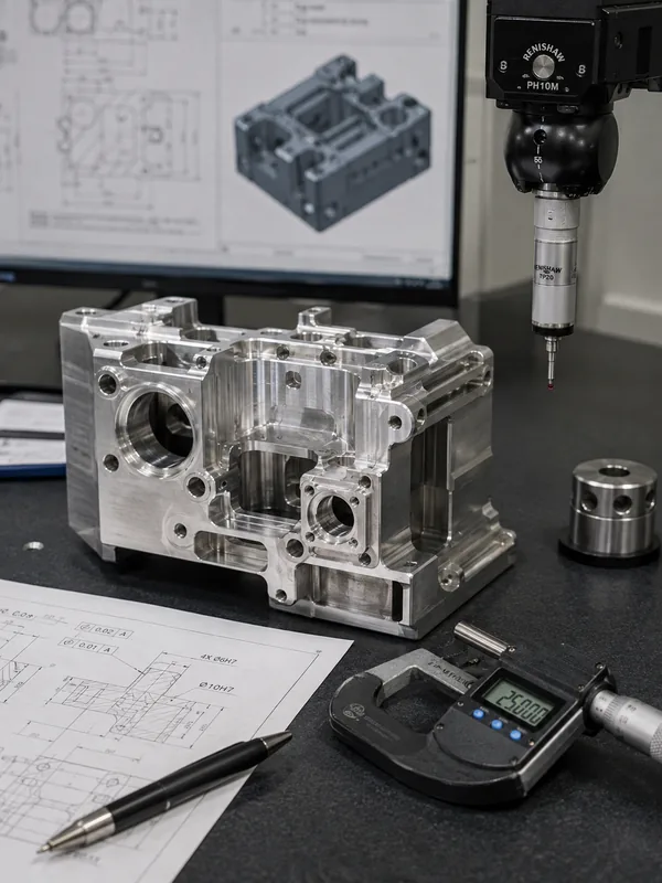
5 Axis CNC Machining Factory for Complex Custom Parts
We manufacture custom multi-sided housings, multi-angle brackets, and complex valve bodies to your exact drawings. Reduce setups, improve datum alignment, and solve difficult tool access.
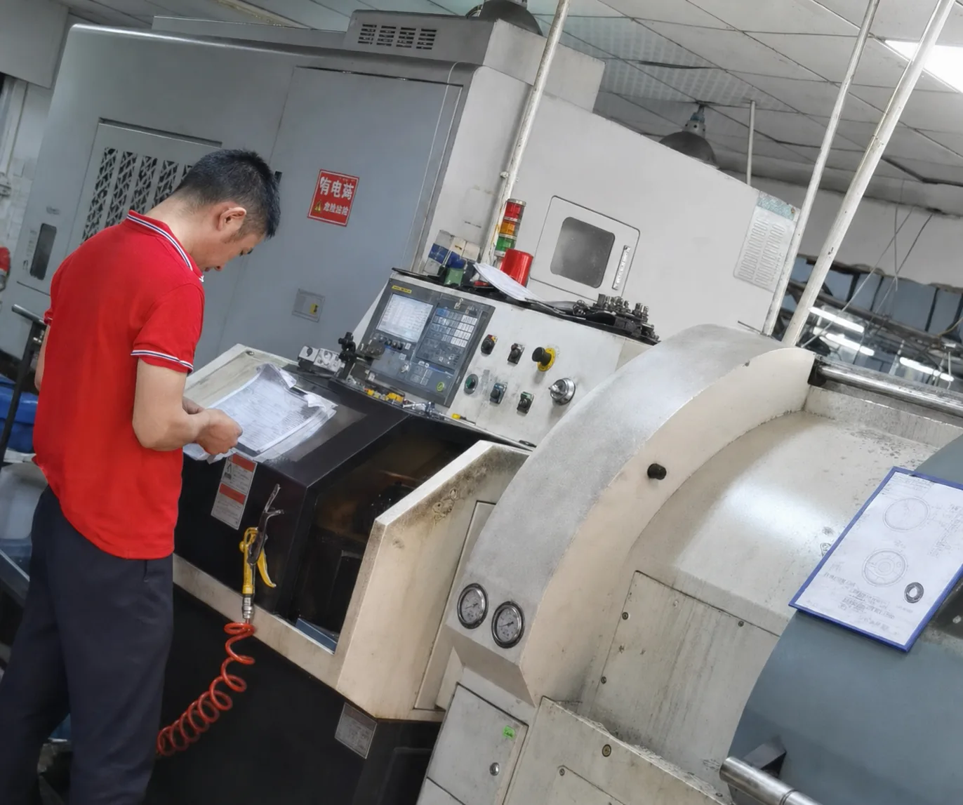
Looking for Machined Parts, Not a 5-Axis Machine?
LuckyHxs supports drawing-based manufacturing for complex CNC components requiring multi-sided features, angled holes, deep cavities, compound surfaces, and difficult tool access. We manufacture custom parts rather than selling CNC machines, machining centers, rotary tables, or replacement machine components.
Custom 5-Axis Machining Capabilities at a Glance
Supply Type
Custom Made to Drawing
Prototypes & Repeat Production
Typical Geometry
Multi-Sided & Compound Angles
Deep cavities, angled holes
Materials
Aluminum, Stainless, Plastics
Subject to capability review
Inspection Focus
Multi-Face Relationships
First article & batch verification
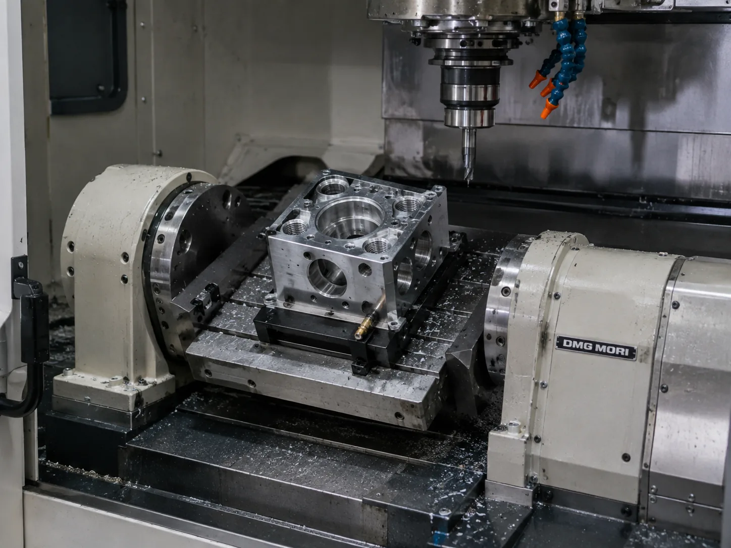
Machine Complex Geometry from More Directions with Fewer Setups
Standard 3-axis machining can only approach a part from the top down. If your part has holes on the sides, angled mounting faces, or complex undercuts, it requires manual re-clamping for every new direction.
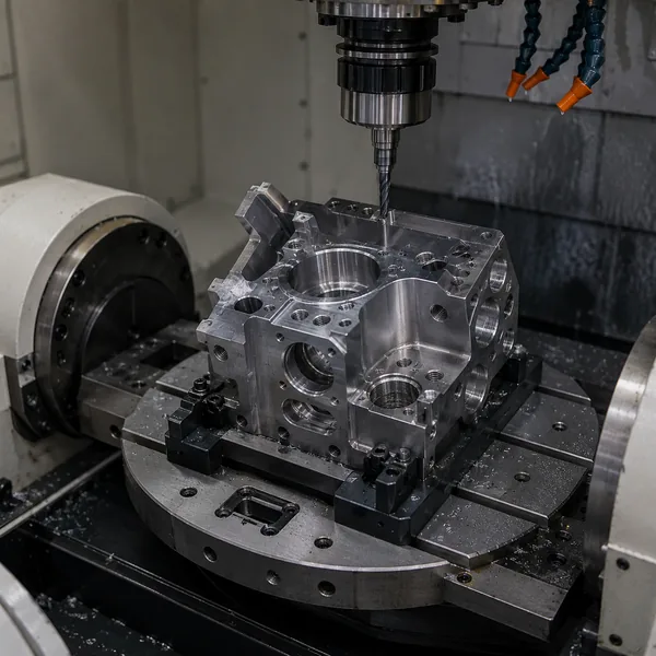
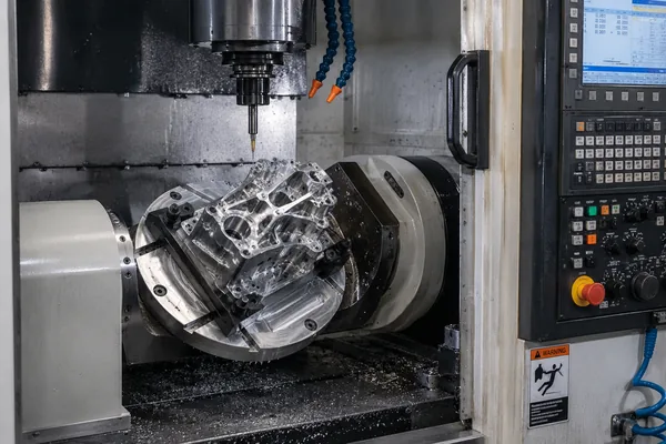
5-axis CNC machining adds two rotary axes, allowing the cutting tool to approach the workpiece from almost any angle in a single setup. This fundamentally changes how complex parts are manufactured—reducing datum transfer errors, eliminating multiple custom fixtures, and maintaining tight geometric relationships across multiple faces.
- Reduced Setups: Fewer manual interventions mean less chance for human error.
- Better Datum Alignment: Features machined in the same setup share the same coordinate origin.
- Shorter Tools: Tilting the part allows for shorter, more rigid cutting tools, reducing vibration.
Complex Parts We Evaluate for 5-Axis Machining
We focus on components where standard 3-axis routing creates too many setups or quality risks.
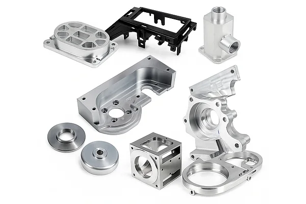
Complex Multi-Sided Housings
Electronic, sensor, and instrument enclosures requiring multiple datums and sealing surfaces.
Features
Internal cavities, side holes, angled threaded holes.
Why Multi-Axis
Reduces re-clamping to maintain position relationships between faces.
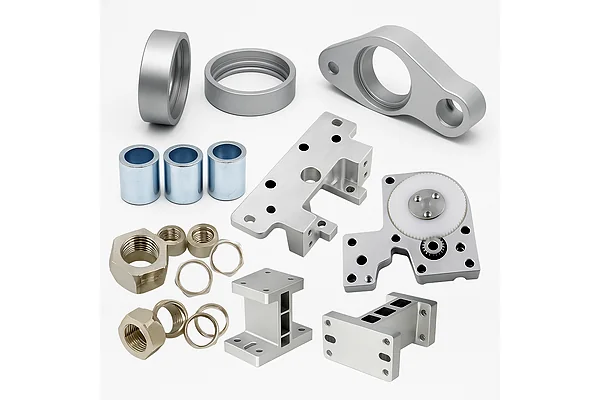
Multi-Angle Brackets
Equipment, sensor, and motor mounts with irregular mounting blocks.
Features
Compound angles, non-orthogonal holes, multiple datum planes.
Why Multi-Axis
Allows machining of angled mounting faces in a single coordinate system.
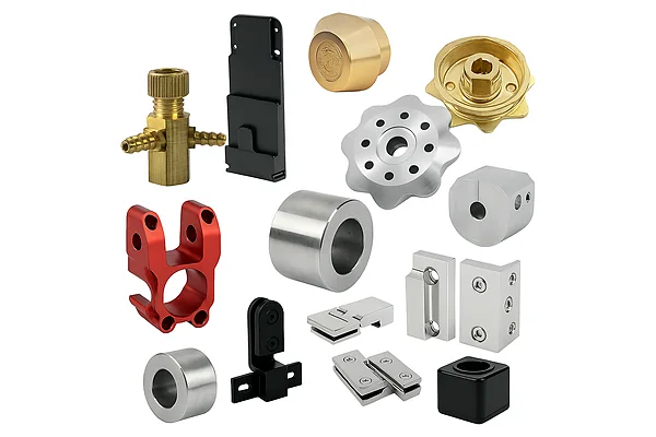
Precision Manifolds & Valve Bodies
Hydraulic and pneumatic blocks requiring complex internal routing.
Features
Cross holes, angled ports, deep bores, sealing surfaces.
Why Multi-Axis
Accesses multiple machining directions without custom angle fixtures.
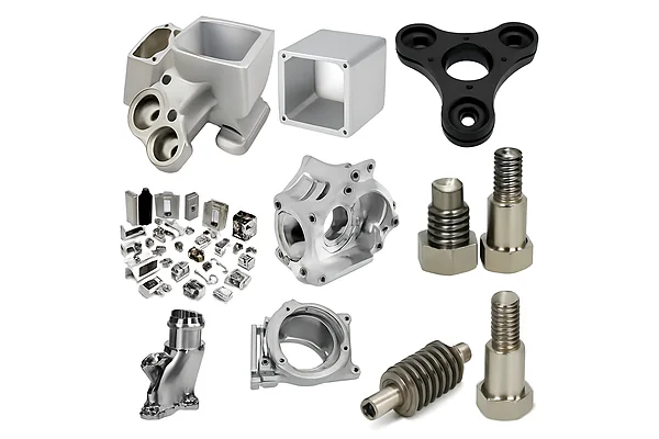
Freeform & Contoured Parts
Sculpted aluminum parts and custom 3D profiles with organic geometry.
Features
Continuous contours, compound curves, multi-angle transitions.
Why Multi-Axis
Simultaneous movement avoids witness lines and improves surface finish.
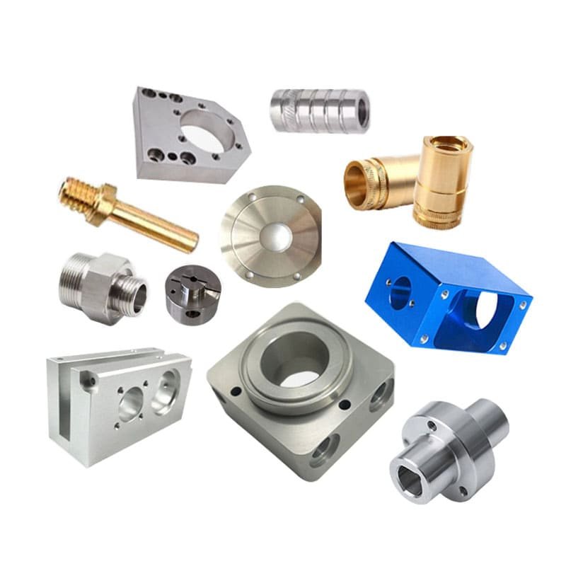
Deep-Cavity & Thin-Wall
Lightweight frames, pocketed structures, and hollow components.
Features
Difficult tool access, deep corners, thin walls susceptible to vibration.
Why Multi-Axis
Tilts the tool to reach deep corners using shorter, more rigid cutters.
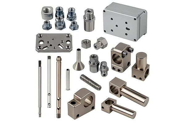
Robotics & Automation
Robot joint housings, end-effector components, and actuator structures.
Features
Lightweight designs, multi-direction mounting holes, precise bearing fits.
Why Multi-Axis
Ensures concentricity and alignment across complex joint assemblies.
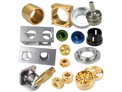
Camera & Optical Components
Lens mounts, optical frames, and precision alignment structures.
Features
Strict alignment tolerances, multi-angle mounting, lightweight pockets.
Why Multi-Axis
Maintains critical optical path relationships in a single setup.
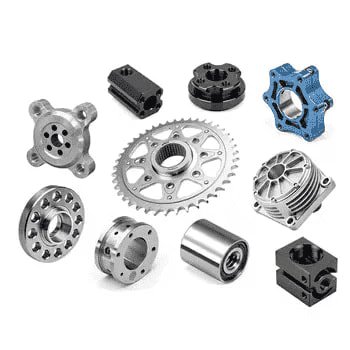
Automotive Complex Parts
Lightweight mounts, suspension prototype components, custom covers.
Features
Complex structural geometry, multi-face mounting, prototype iteration.
Why Multi-Axis
Rapidly machines complex billet structures without expensive tooling.
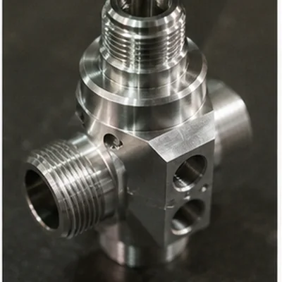
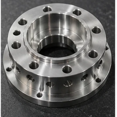
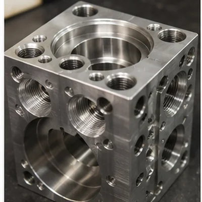
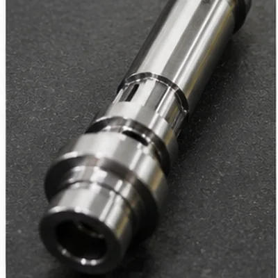
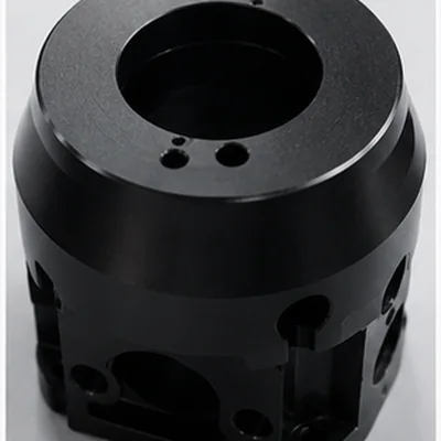
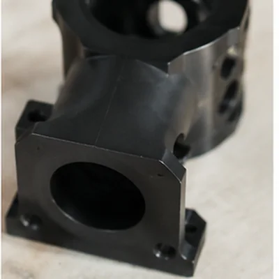
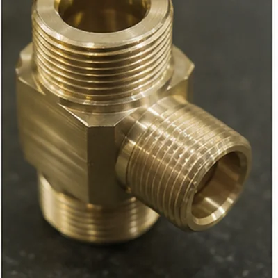
Custom Complex CNC Part Structures
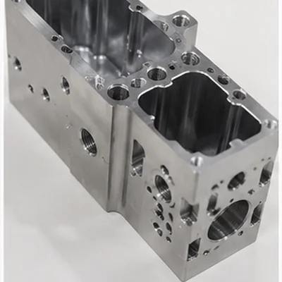
When Complex Geometry Starts Creating Too Many Setups
Not every part needs advanced multi-axis machining. But when part geometry forces multiple manual re-clampings, quality risks and costs increase.
3-Axis Milling
Best for parts where all features can be reached from one or two orthogonal directions.
- • Simple flat plates
- • Basic rectangular blocks
- • Single-face pockets
3+2 Axis (Positional)
Rotary axes position the part, then lock. Ideal for multi-sided features without continuous motion.
- • Multi-sided housings
- • Angled holes & tapped ports
- • Compound mounting faces
Simultaneous 5-Axis
All 5 axes move at once. Required for complex organic shapes and continuous tool re-orientation.
- • Freeform surfaces
- • Continuous contours
- • Deep cavities needing tool tilt
Why Complex CNC Parts Still Fail in Production
Even with advanced machinery, manufacturing complex parts to drawing specifications requires rigorous engineering. These are the most common failures buyers experience when sourcing multi-axis components.
1. Multi-Sided Features Don't Align
Individual hole sizes pass, but their relationship across different faces fails during assembly.
2. Deep Cavities Fall Short
Inaccessible corners retain material, or long tools cause severe chatter marks on walls.
3. Sample-to-Batch Geometry Drifts
The prototype passed inspection, but production batches show drifting angled hole positions.
Multi-Sided Features Don’t Align
The Challenge
Complex housings and brackets have multiple holes, angled faces, and mounting surfaces. Each individual dimension might pass inspection, but their positional relationship fails, causing screws to misalign or mating parts to interfere.
Why It Happens
- Repeated manual setups and datum transfer errors.
- Fixture variation and work offset changes.
- Inconsistent setup strategy across multiple faces.
How LuckyHxs Helps
We review critical feature relationships before machining to identify functional datums. By utilizing multi-axis equipment, we evaluate opportunities to reduce re-clamping. We monitor critical multi-face dimensions, checking hole-to-hole relationships and angled features to verify final geometry according to drawing requirements.
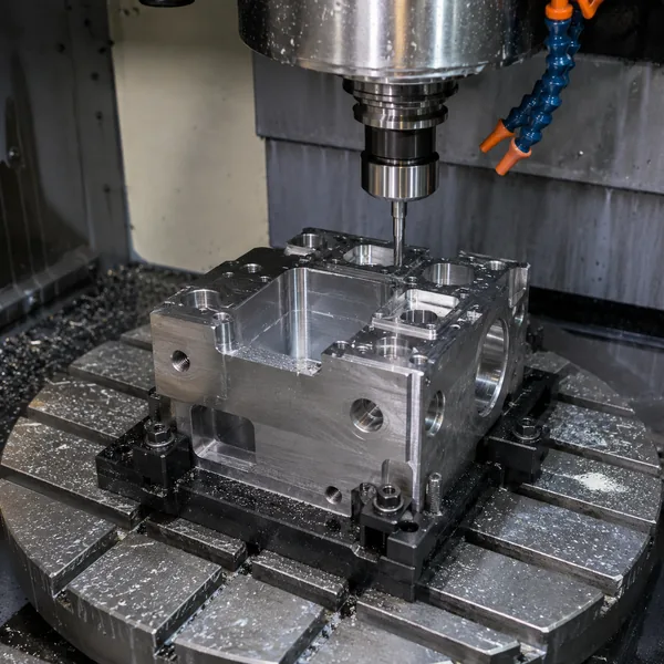
Deep Cavities & Complex Surfaces Fall Short
The Challenge
Parts return with leftover material in inaccessible corners, chatter marks on deep walls, witness lines on contoured surfaces, or uneven freeform transitions.
Why It Happens
- Excessive tool stick-out causing vibration.
- Poor tool approach angle or collision restrictions.
- Inadequate tool rigidity for the required depth.
How LuckyHxs Helps
During DFM review, we evaluate tool access and cutter orientation. Where geometry permits, we use machine tilting to allow shorter, more rigid tools. We plan deep cavity machining sequences carefully and inspect functional cavity dimensions, wall geometry, and surface continuity.
Sample-to-Batch Geometry Drifts
The Challenge
The prototype passed perfectly, but the production batch drifted. Angled hole positions change, thin walls distort, or mounting features show variation.
Why It Happens
- Tool wear over long production runs.
- Inconsistent fixture clamping or thermal effects.
- Work offset changes between different machine setups.
How LuckyHxs Helps
We rely on strict first article verification and in-process dimensional checks. We monitor tool wear and identify critical feature positions early. Repeat-order requirements and specific CAM/setup strategies are retained to ensure batch consistency matches the approved prototype.
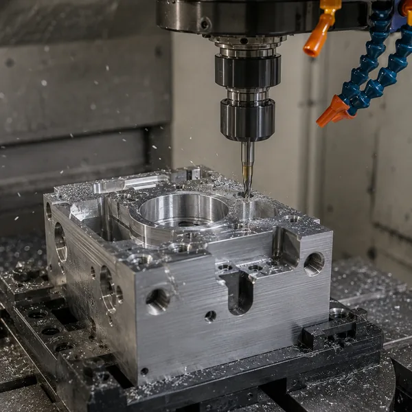
More Risks to Review Before Complex Machining
4. Long Tool Chatter
Surface marks caused by extended tool reach.
5. Freeform Waves
Witness lines on continuous contoured surfaces.
6. Thin-Wall Deformation
Parts warp or deform after unclamping from the fixture.
7. Interference
Tool or fixture blocks critical machining access.
8. Internal Burrs
Cross holes and internal features retain difficult burrs.
9. Rotary Errors
Coordinate errors directly affect complex geometry.
10. Compound Angles
Incorrect setup leads to failing angled hole positions.
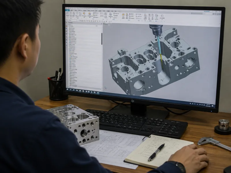
Review Tool Access Before Cutting Metal
Complex CNC machining requires thorough Design for Manufacturability (DFM) review. We evaluate your CAD model to ensure features can actually be reached and machined to your specified tolerances.
Materials for Complex CNC Machined Parts
Aluminum
6061, 6063, 7075, 2024, 5052
Stainless Steel
303, 304, 316, 316L
Free-Machining Steel
1214, 1215
Brass & Copper
Standard alloys
Plastics
POM / selected engineering plastics
Other materials subject to drawing and capability review during quotation.
5-Axis Results Depend on More Than the Machine
Having access to a 5-axis machine does not automatically guarantee a correct complex part.
CAM Planning
Datum Strategy
Workholding
Tool Selection
Tool Length
Collision Avoidance
Cutting Sequence
Calibration
Inspection Planning
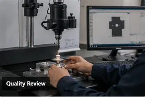
Inspection for Multi-Sided and Complex Geometry
Drawing Review
Review tolerances and requirements.
Critical Feature ID
Identify relationships between faces.
Datum Review
Establish measurement origins.
First Article
Verify initial prototype geometry.
In-Process Checks
Monitor dimensions during run.
Burr & Surface
Review cross holes and finishes.
Final Inspection
Dimensional verification against drawing.
Batch Verification
Ensure consistency across the order.
Where Complex Multi-Axis Machining Adds Value
Robotics & Automation
Useful for lightweight structures and multi-direction joint features.
Automotive & EV
Useful for complex prototype structures and custom housings.
Camera & Optical
Useful for strict alignment and complex mounting geometry.
Precision Instruments
Useful for multi-sided sensor enclosures.
Electronics & Sensors
Useful for internal cavities and angled threaded holes.
Industrial Machinery
Useful for multi-angle brackets and structural supports.
Fluid Control
Useful for multi-directional ports and cross holes in valve bodies.
Medical Components
Useful for complex non-implant equipment housings.
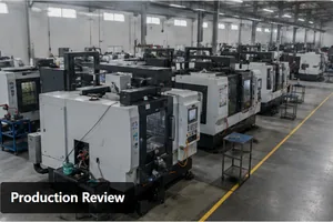
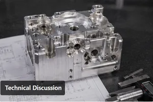
A Manufacturing Partner You Can Verify
What Is a 5-Axis CNC Mill?
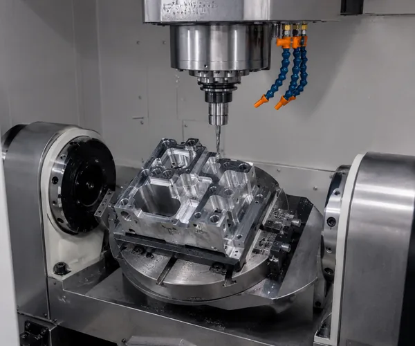
A standard 3-axis CNC machine moves a cutting tool across the X, Y, and Z linear axes. A 5-axis CNC mill adds two rotary axes (often A and B, or A and C), allowing the tool or the table to tilt and rotate.
Why Does Fewer Setups Matter?
Repeating setups for multiple sides increases positioning errors, datum transfer errors, the need for additional fixtures, and overall handling time.
3+2 vs Simultaneous 5-Axis
3+2 (Indexed Machining): The rotary axes position the workpiece and lock before cutting. Ideal for angled holes, side features, and multi-face machining.
Simultaneous: Rotary and linear axes move during machining. Ideal for continuous contours, complex curved surfaces, and changing tool orientation.
What Are Common 5-Axis CNC Machining Projects?
-
Multi-Sided Housings
Why: Requires multiple faces, holes, and cavities.
-
Multi-Angle Brackets
Why: Requires compound mounting angles.
-
Manifolds & Valve Bodies
Why: Requires multi-directional ports and cross holes.
-
Deep-Cavity Components
Why: Features difficult tool access.
-
Freeform Surface Parts
Why: Requires continuous contours.
-
Robotics Components
Why: Lightweight structures + multi-direction features.
-
Optical & Camera Components
Why: Alignment + complex mounting geometry.
-
Automotive Development Parts
Why: Complex prototype structures.
Does Every Complex CNC Part Need 5-Axis?
No. If the structure can be completed more economically through 3-axis milling, CNC turning, turn-mill, or 3+2 positional machining, a simpler routing should be chosen.
What Are the Disadvantages of 5-Axis Machining?
-
1. More Complex Programming
Requires complex CAM and tool axis planning.
-
2. Collision Risk
Tool, holder, fixture, spindle, or workpiece may interfere.
-
3. Workholding Is More Difficult
Fixtures must be stable without blocking rotation or tool paths.
-
4. Calibration Matters More
Rotary-axis geometry directly affects complex feature relationships.
-
5. Inspection Is More Difficult
Complex angles and freeform surfaces cannot rely on simple calipers.
-
6. Higher Manufacturing Cost
For simple parts, using 5-axis may not make economic sense.
-
7. Skilled Engineering Required
Requires more CAM, process planning, simulation, and fixture design.
Frequently Asked Questions About 5-Axis CNC Machining
What types of parts are best suited for 5-axis machining?
What is the difference between 3-axis and 5-axis CNC machining?
What is the difference between 3+2 and simultaneous 5-axis machining?
Can 5-axis machining reduce the number of setups?
Can complex angled holes and deep cavities be machined?
What CAD files should I send for a quotation?
Which materials can be used for complex CNC parts?
How are complex multi-sided components inspected?
Have a Complex Part That Takes Too Many Setups?
Send us your 2D/3D drawing, material, quantity, critical datums, tolerance requirements, and surface finish. Our team will review the geometry and determine a practical CNC machining route for your project.