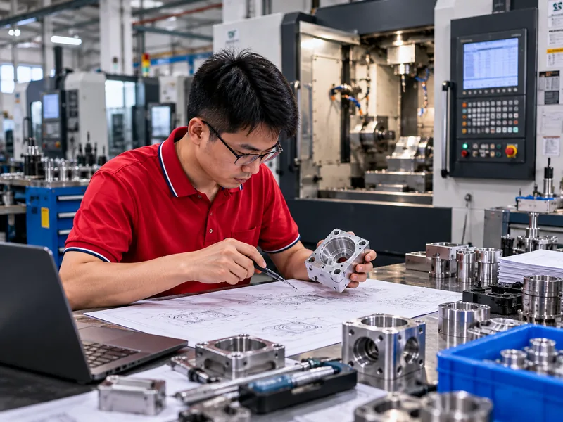
Custom CNC Milling Machine Parts Manufacturer
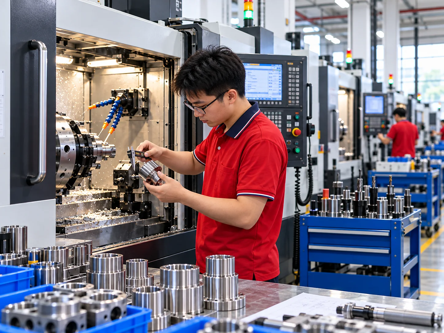
LuckyHXS manufactures drawing-defined mechanical components used in CNC milling machines, including housings, bearing mounts, support blocks, brackets, plates, manifolds and protective parts. We review geometry, material, functional interfaces, finishing and inspection requirements before selecting the machining route.
- Custom manufactured from 2D/3D drawings
- Metal and engineering-plastic options
- Prototype validation through repeat production
- Tolerance and inspection plans matched to critical features
Looking for a branded catalog spare? Compatibility must be verified from complete technical information before quotation.
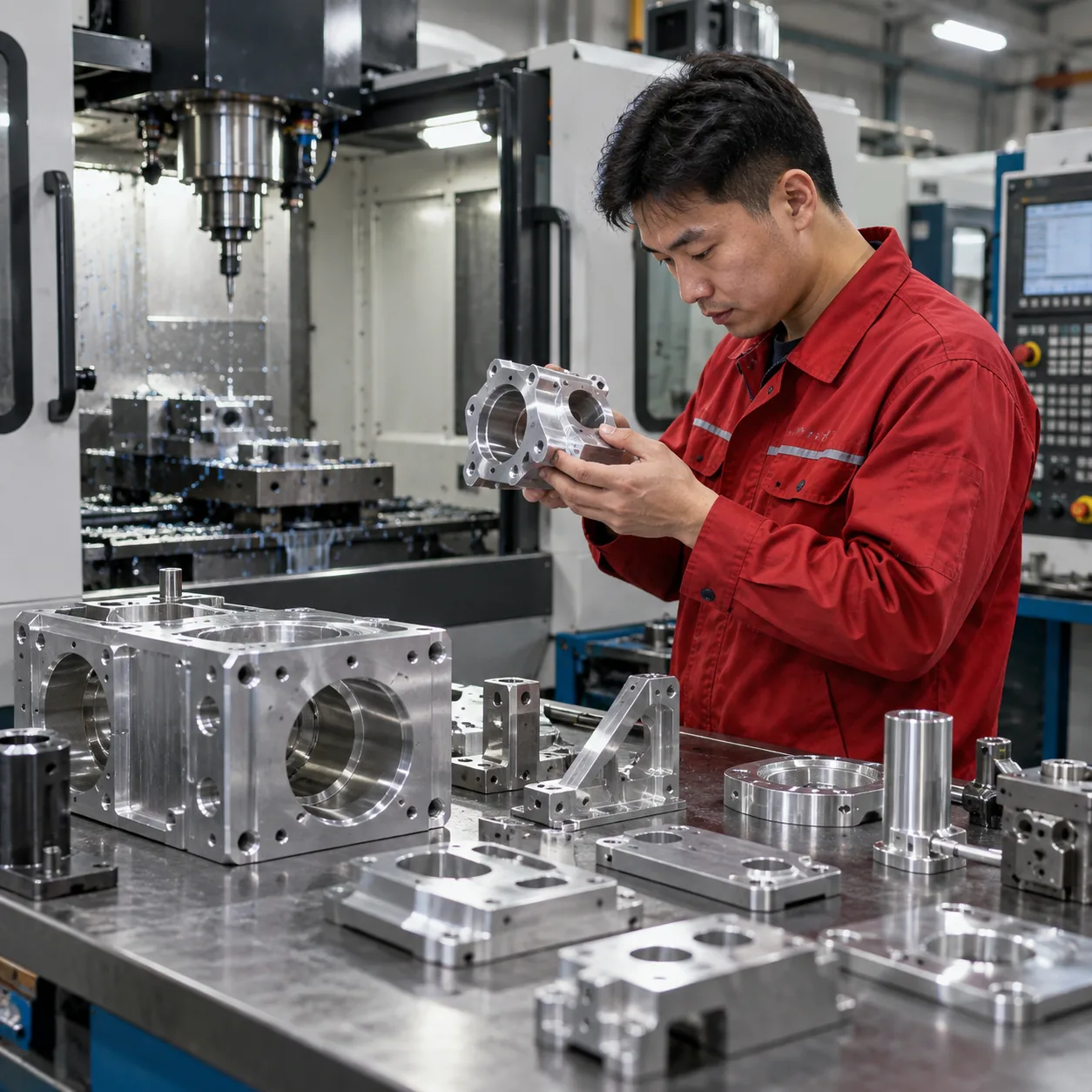
Custom Mechanical Parts for CNC Milling Equipment
This page covers mechanical components manufactured to customer drawings for machine building, repair, retrofit and production-equipment projects. The correct material, datum system, mating dimensions and inspection method are confirmed for each part.
- Supply type: Made-to-drawing custom components
- Typical forms: Housings, mounts, plates, supports, blocks, brackets and covers
- Processes: CNC milling, drilling, tapping, boring and coordinated secondary operations
- Materials: Aluminum, stainless steel, carbon/free-machining steel, brass and selected engineering plastics
- Tolerance ref: ±0.01 mm where the part and inspection plan permit
- Order path: Drawing review, quotation, sample validation and repeat production
LuckyHXS does not present complete motors, controllers, ball screws, linear guides or branded assemblies as standard stock. We manufacture the drawing-defined mechanical part around or supporting those systems.
CNC Milling Machine Components Made to Your Design
Select the component family closest to your project. Every item is evaluated from the drawing rather than from a generic machine model name.
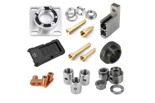
Spindle Housings & Bearing Mounts
Machined housings, bearing seats and mounting structures that support spindle or rotating assemblies. Critical review points include bore relationships, mounting faces, bearing fits, wall thickness and datum alignment.
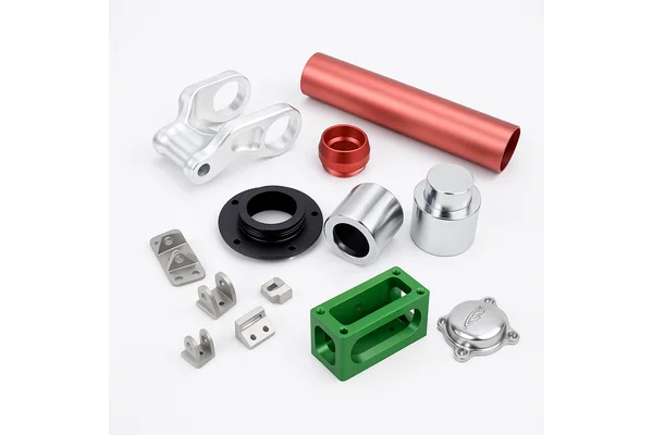
Motor Mounts & Drive Brackets
Motor plates, drive brackets and connection structures used to position motors, couplings or transmission elements. Hole-pattern accuracy, stiffness, alignment and assembly access guide the machining plan.
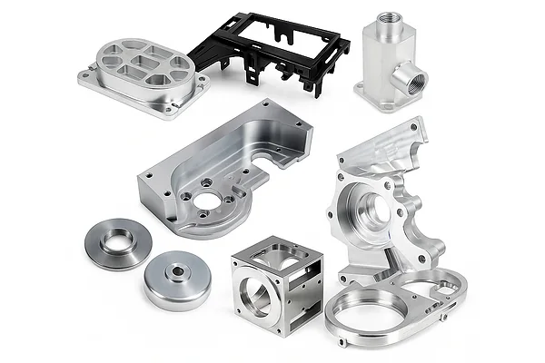
Machine Tables, Plates & Fixtures
Custom plates, fixture bases, locating plates and workholding structures for machine setup or production support. Functional datums, flatness, slot geometry and replaceable locating features require coordinated review.
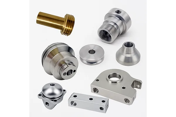
Ball-Screw Supports & Bearing Blocks
Support housings and bearing blocks around linear-drive systems. These are custom mechanical supports—not ball screws or bearings themselves. Bore fits, axis height, mounting faces and paired-part alignment must be defined.
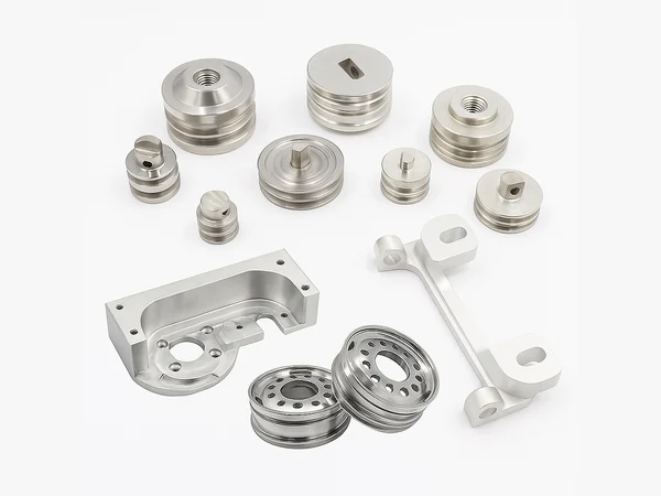
Linear-Guide Mounting Components
Rail mounting plates, carriage blocks and supporting structures manufactured to a defined reference system. Straightness, parallelism, hole position and mounting-surface preparation are reviewed together.
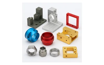
Tool-Changer Plates & Mechanical Brackets
Drawing-defined plates, arms, brackets and support components used around tool-handling mechanisms. This scope excludes the complete automatic tool changer and its electrical controls.
Coolant & Lubrication Manifolds
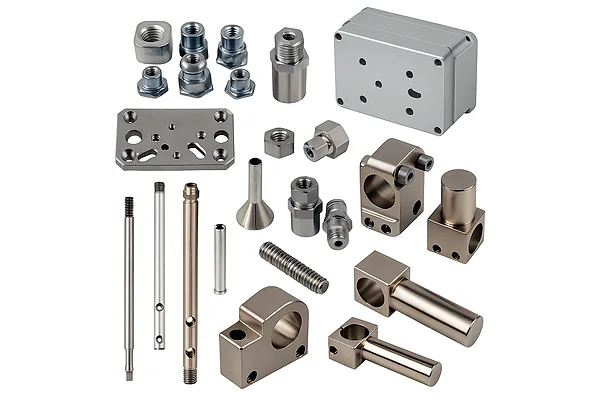
Machined blocks and distribution components with threaded ports, cross holes and sealing surfaces for coolant or lubrication routing. Internal burr control, passage communication and cleanliness are key review points.
Protective Covers, Panels & Enclosures
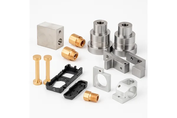
Machined covers, access plates, control enclosures and protective structures requiring mounting interfaces, connector openings or cosmetic surfaces. Confirm sealing, edge, finish and assembly requirements in the drawing.
If your part does not fit one family, send the drawing. Non-standard geometry can be evaluated without being forced into an inaccurate catalog category.
CNC Milling Machine Parts vs. CNC Milled Parts
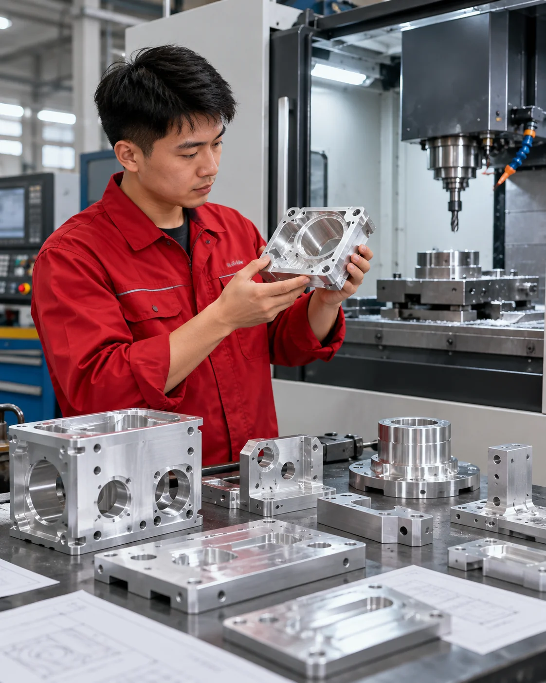
The wording is similar, but the buying requirements are different. Clarifying the product object prevents an incorrect quote and avoids assuming that a custom part is a stocked spare.
| Search or project need | What it normally means | LuckyHXS scope |
|---|---|---|
| CNC milling machine parts | Components that form, support or protect a milling machine | Custom mechanical items can be evaluated from drawings |
| CNC machine spare parts | Replacement items required for maintenance | Only drawing-defined machinable parts; no automatic OEM equivalence |
| CNC milling parts | Components produced by a CNC milling process | Core custom-manufacturing scope |
| Milling machine accessories | Vises, cutters, probes, electronics or off-the-shelf attachments | Not presented as a stocked accessory catalog |
| Brand/model replacement part | Item expected to match an existing machine | Requires complete dimensions, material, interfaces and lawful technical information |
If you need a mechanical housing, support, plate, block, bracket or cover manufactured to your technical definition, this page is the correct route. If you need a complete branded assembly, contact the original machine manufacturer or an authorized parts channel.
When the Original Mechanical Part Is Unavailable
A discontinued or damaged machine component cannot be reproduced accurately from a name alone. The functional interfaces—bearing seats, mounting faces, hole patterns, sealing surfaces and adjacent clearances—must be recovered and documented before machining.
- 1 Situation — The original component is worn, damaged or no longer supplied.
- 2 Risk — Copying worn dimensions can reproduce the failure rather than the intended geometry.
- 3 Response — Use an available drawing, unworn reference surfaces, mating-part information and inspection data to establish the manufacturing definition.
- 4 Procurement value — A documented drawing and inspection plan create a controlled basis for sample validation and future repeat orders.
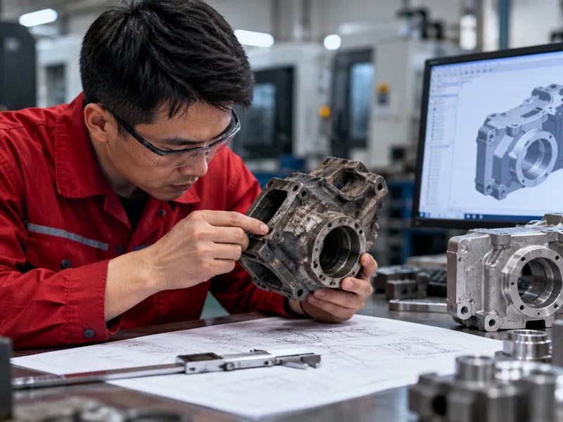
A physical sample proves the visible condition of one item. It does not automatically define the original design tolerance or material grade.
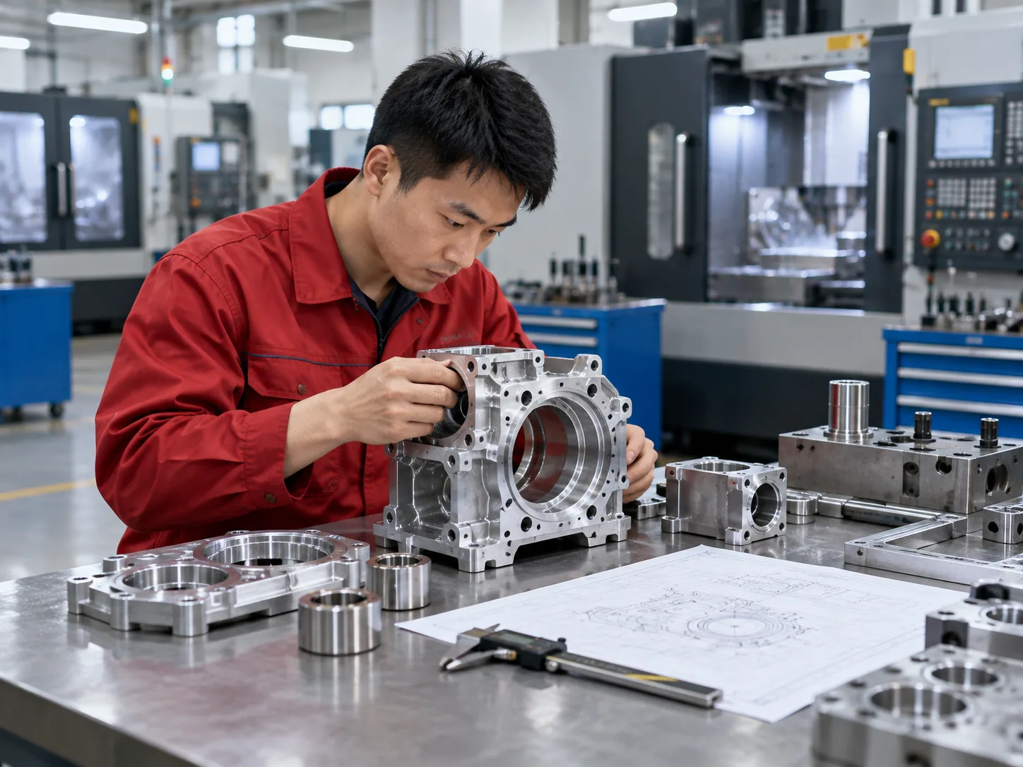
A Part Can Pass Individual Dimensions and Still Misalign
Machine components work through relationships. A bearing bore can be within size while its centerline is wrong relative to a mounting face. A rail plate can have correct holes while the pattern is not parallel to the working datum. Inspection therefore needs to follow the assembly function, not only a list of isolated dimensions.
Relationship checklist:
- Bore axis to mounting face
- Paired bearing locations and center height
- Rail datum to threaded-hole pattern
- Motor centerline to driven component
- Manifold ports to sealing faces
- Cover openings to connectors and service access
Define the functional datum and mating conditions on the drawing wherever they control assembly or motion.
Surface Treatment Changes the Finished Interface
Anodizing, plating, black oxide, passivation, polishing and blasting are not only appearance choices. Coating or material removal can affect threaded holes, bearing fits, sealing faces, sliding surfaces and electrical contact areas.
| Feature | Pre-finish question | Final verification direction |
|---|---|---|
| Bearing bore | Is the stated size before or after finishing? | Confirm the finished fit and measurement point |
| Threaded hole | Will coating alter engagement? | Define masking, allowance and post-finish gauge check |
| Rail or mounting face | Can the surface receive coating? | Protect or re-establish the functional interface as specified |
| Sealing face | Is roughness or flatness controlled? | Avoid uncontrolled blasting or polishing |
| Cosmetic enclosure | Which faces are appearance-critical? | Define color, texture and permitted fixture marks |
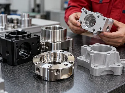
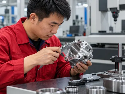
Machining Routes Matched to Component Geometry
The manufacturing route should follow the complete geometry rather than the keyword used in the inquiry.
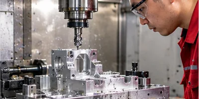
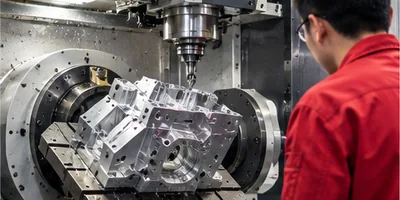
3-Axis CNC Milling
Best suited for plates, brackets, pockets, slots and accessible hole patterns.
Multi-Side Milling
For components requiring machined features across multiple faces with controlled positional relationships.
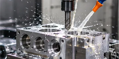
Drilling, Tapping & Boring
Used for mounting holes, threaded ports, bores and controlled internal features.
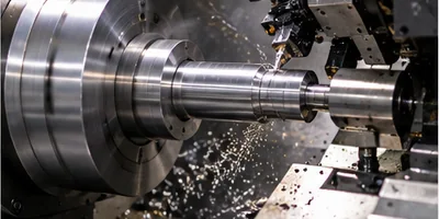
Turn-Mill Coordination
For mainly rotational parts that also require flats, cross holes, slots or side features.
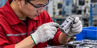
Secondary Deburring & Cleaning
Controlled removal of burrs around edges, holes, threads and internal passages.
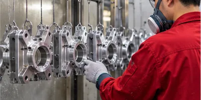
Surface Treatment Coordination
Process planning around coating allowance, masking, appearance and final dimensions.
Boundary: Machine configuration, travel, work envelope and feature capability must be confirmed against the actual drawing. Do not publish an assumed maximum part size or 5-axis capability without current equipment evidence.
Project Parameters We Can Evaluate
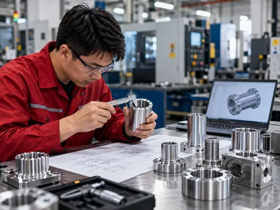
Note: Exact values, inspection scope and documentation are agreed for the project. No generic table overrides the approved drawing.
| Parameter | Available direction | What determines final acceptance |
|---|---|---|
| Part type | Housing, mount, plate, support, block, bracket, manifold, cover or other custom geometry | Complete drawing and functional scope |
| Material | Aluminum, stainless steel, carbon/free-machining steel, brass, copper and selected plastics | Grade availability, function and finishing requirements |
| Standard tolerance reference | ±0.01 mm capability reference | Feature size, geometry, material, setup, finish and inspection method |
| Critical relationships | Bore alignment, hole position, flatness, parallelism, perpendicularity and fit | Datum definition and functional requirement |
| Quantity | Prototype validation through repeat production | Part complexity, tooling, material and production plan |
| Files | 2D drawings and 3D engineering models | Controlled revision and complete dimensions/tolerances |
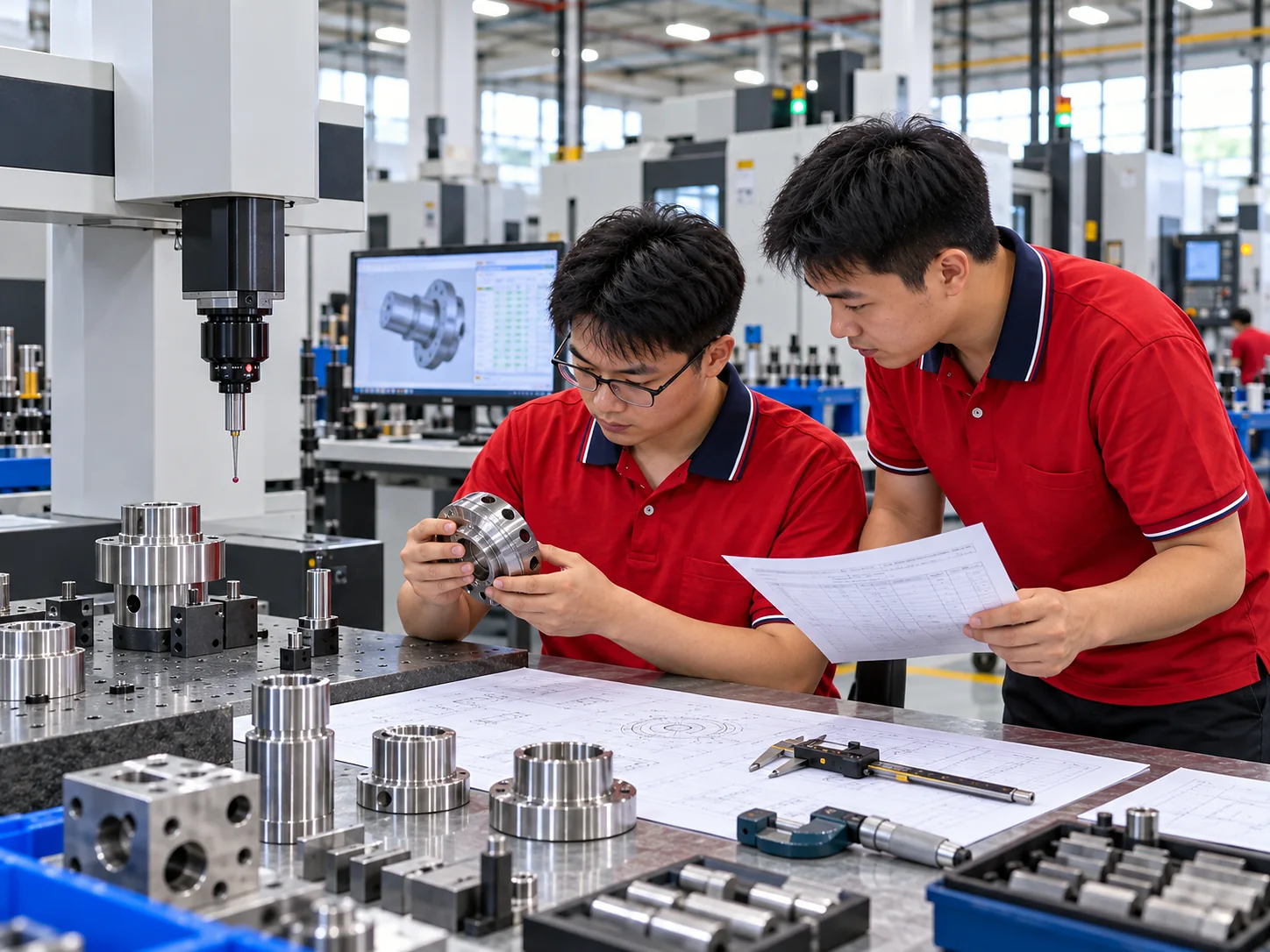
| Inspection | Calipers, micrometers, gauges, optical measurement or CMM as appropriate | Feature, tolerance and agreed inspection plan |
| Finishing | Project-dependent machining and coordinated secondary treatment | Material, protected interfaces, appearance and final dimensions |
Material Choices for Structure, Wear, Corrosion and Weight
Material selection starts with the component’s load, mating interfaces, operating environment, wear points, finishing and dimensional-stability needs.
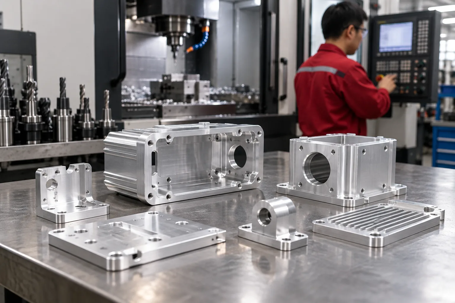
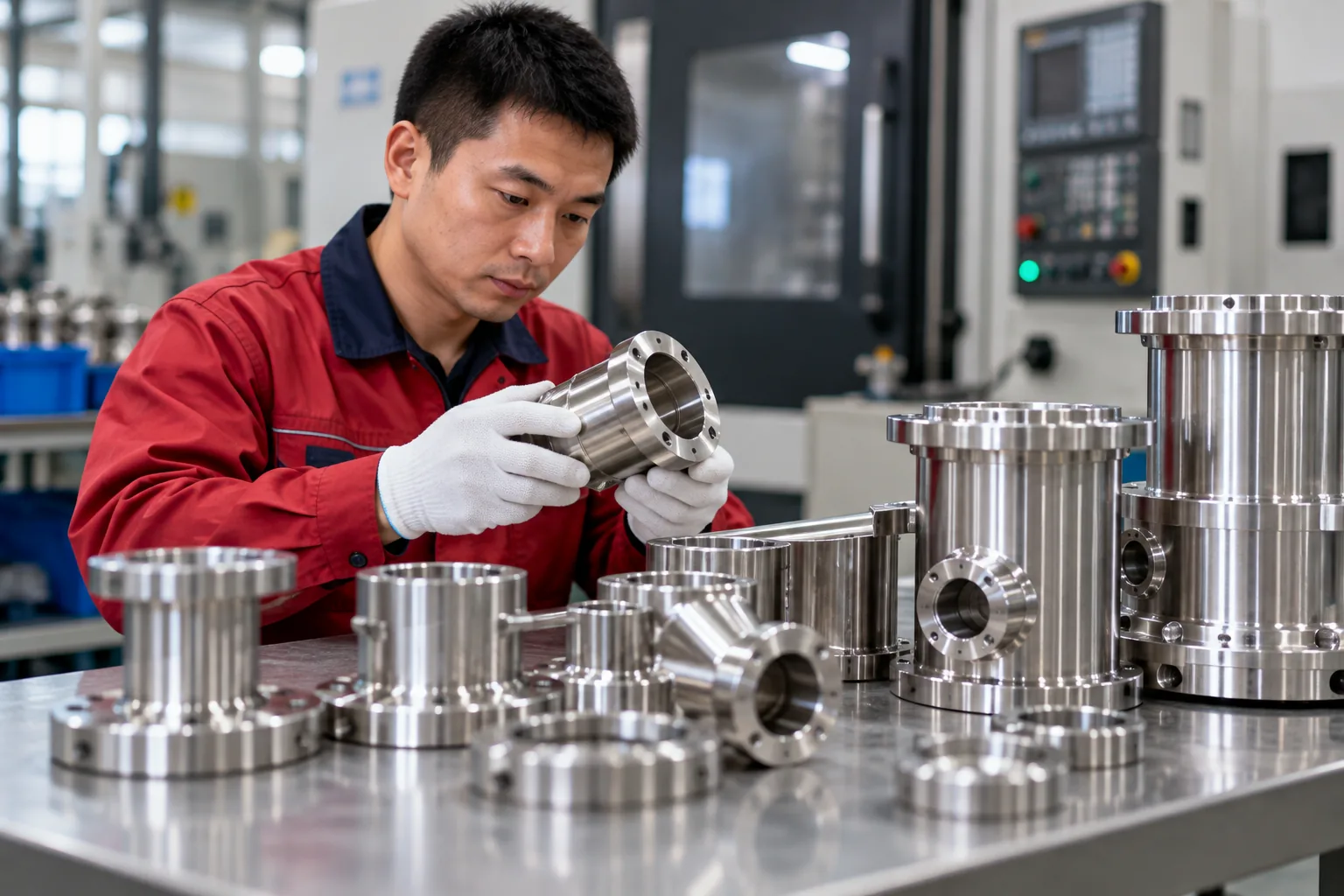
- Aluminum alloys Useful for covers, brackets, mounting plates, housings and other components where weight and machinability matter. Available grades must be confirmed for the project. Explore aluminum CNC machining
- Stainless steels Considered for corrosion exposure, clean equipment environments and components requiring stainless interfaces. Machinability and distortion risk vary by grade. Review stainless steel machining considerations
- Carbon and free-machining steels Suitable for selected supports, pins, blocks and mechanical components where strength, cost or productive machining is important. Corrosion protection must be specified where needed.
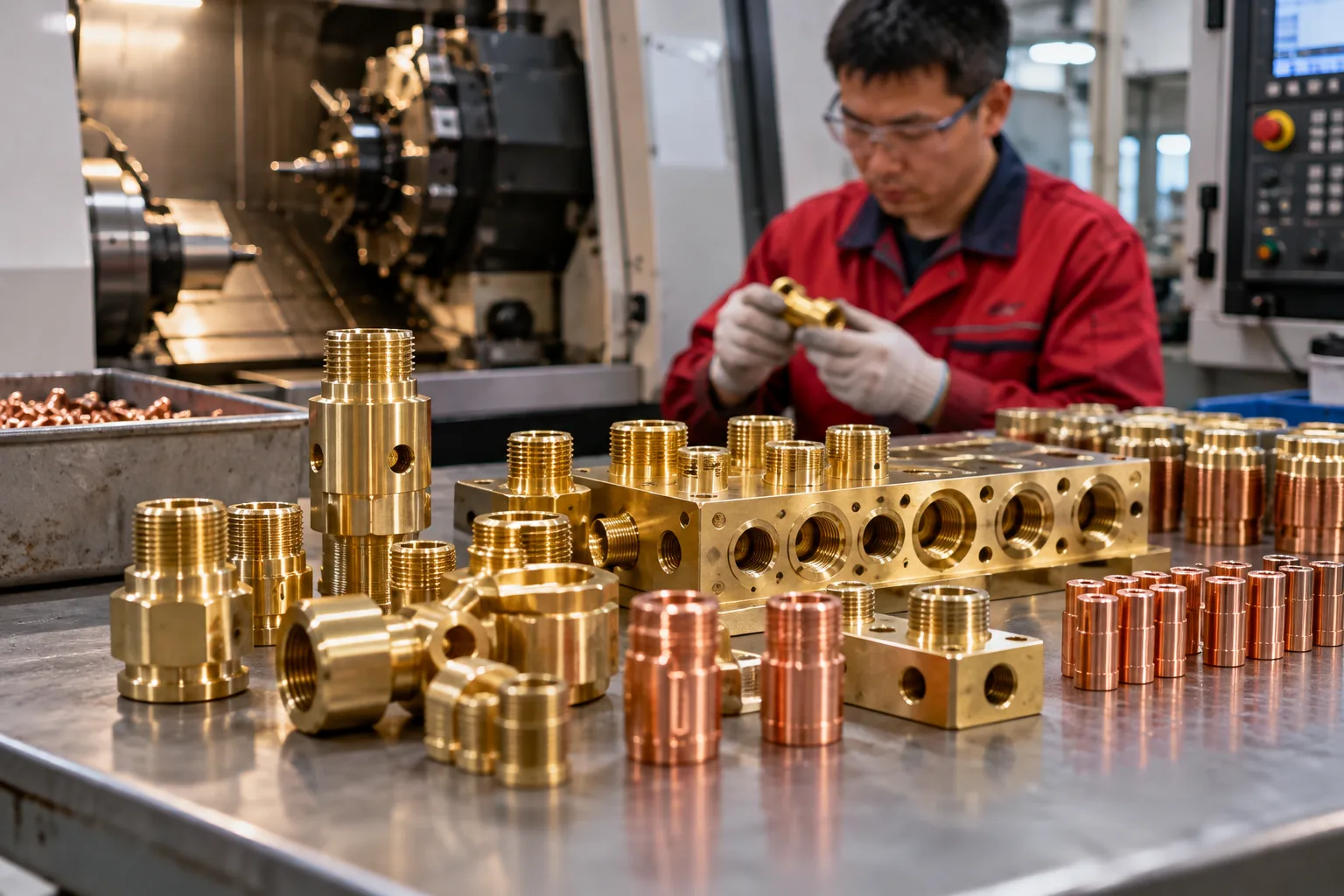
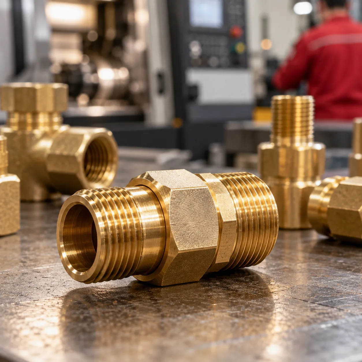
- Brass and copper alloys Appropriate for selected fittings, manifolds, electrical interfaces and low-friction components when the drawing supports them.
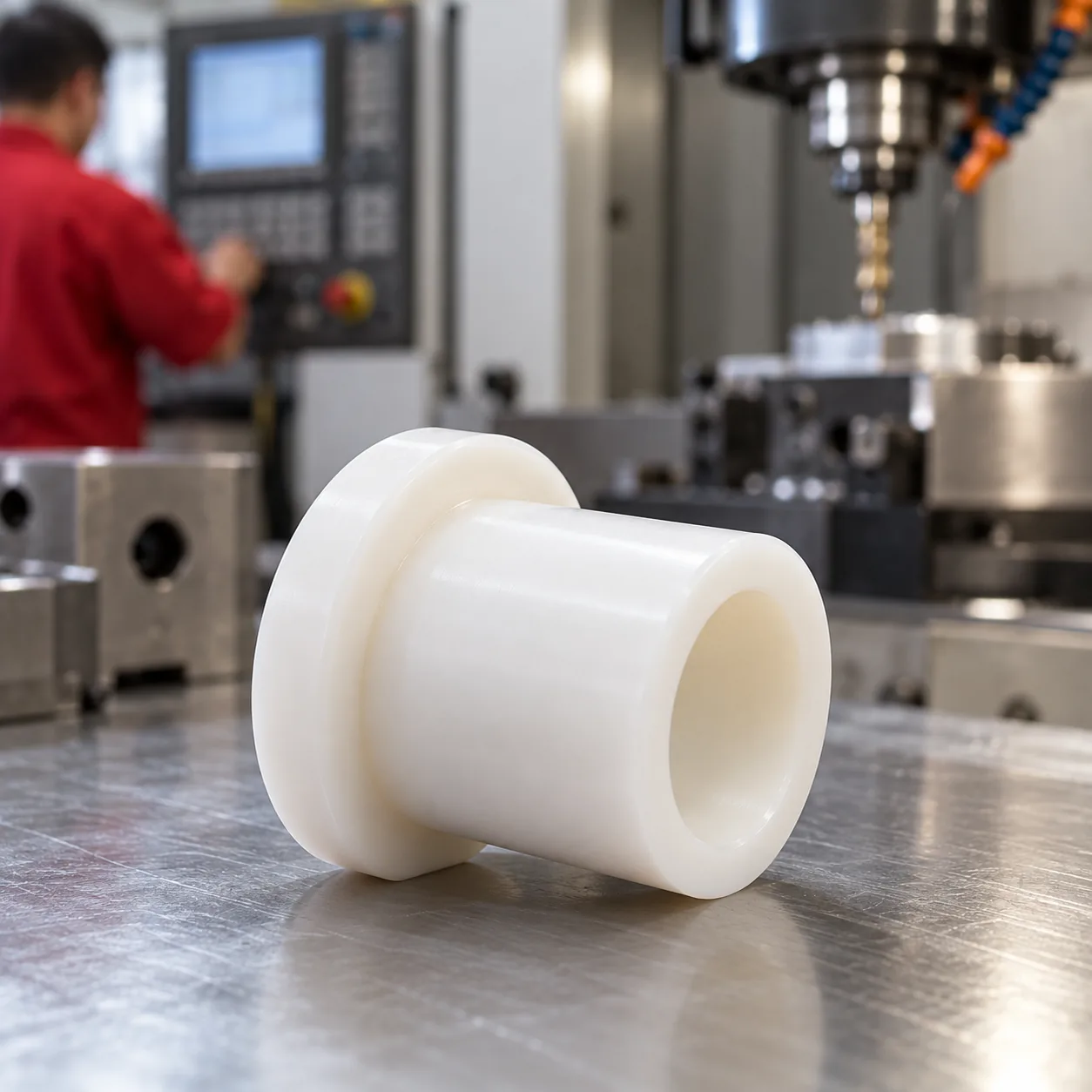
- Engineering plastics POM, PTFE and other confirmed grades may suit insulators, guides, low-friction parts or lightweight covers. Temperature, creep, moisture and dimensional behavior require review.
Match the Material to the Functional Requirement
| Requirement | Common starting direction | Review before selection |
|---|---|---|
 Lower moving mass
|
Aluminum alloy | Stiffness, wall thickness, thread life and finish |
 Corrosion exposure
|
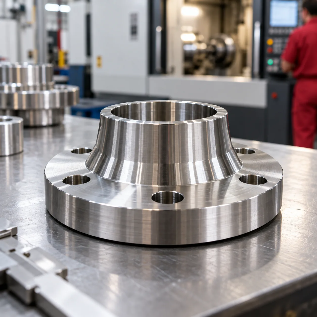
Stainless steel or protected metal | Exact environment, grade and galvanic contact |
 Economical mechanical support
|
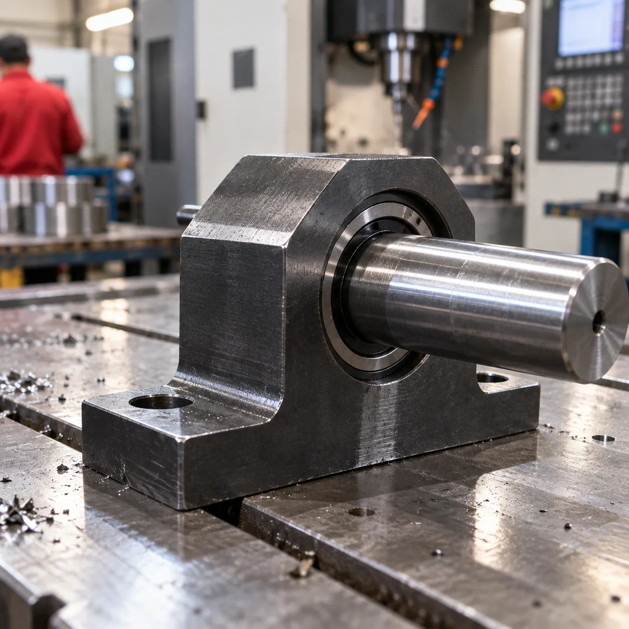
Carbon/free-machining steel | Strength, weldability if applicable and corrosion protection |
 Electrical or fluid interface
|
Brass/copper alloy where suitable | Pressure, conductivity, thread and material compatibility |
 Low friction or insulation
|
Engineering plastic | Creep, temperature, wear and fastening method |
 Bearing or rail interface
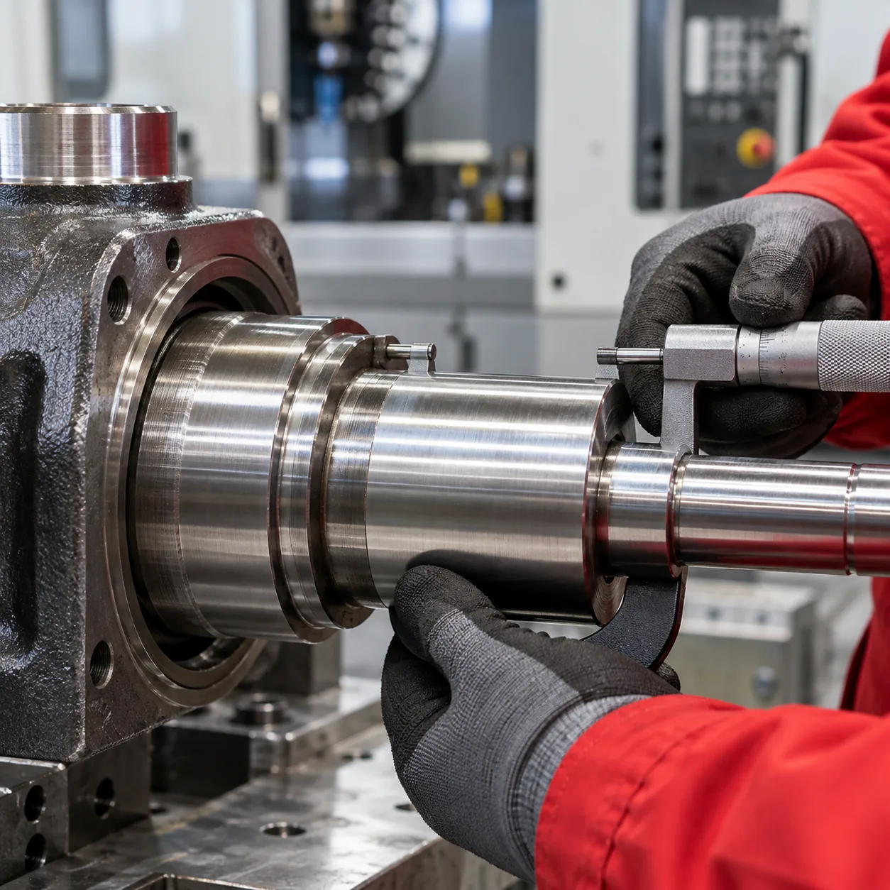
|
Drawing-specific metal and heat-treatment condition | Fit, hardness, surface condition and inspection |
This matrix is selection guidance, not a material specification. The approved drawing controls production.
Drawing Review Before Material Is Cut
A practical engineering review aligns drawing intent, function and inspection requirements before quotation becomes a production commitment.
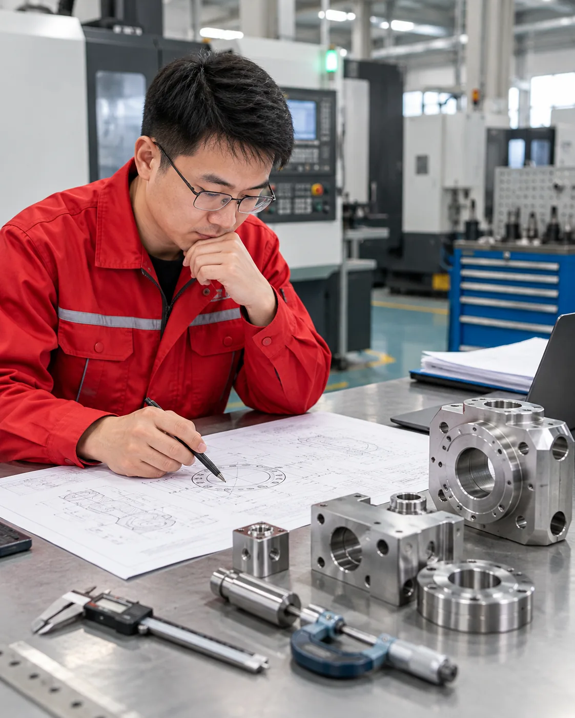
Product Identity
Confirm whether the request is for a custom machined component, a purchased assembly or a branded replacement part.
Datums & Interfaces
Identify mounting faces, axes, bearing seats, sealing surfaces and mating-hole relationships.
Machining Access
Review tool access, internal corners, slot depth, cross holes and side-feature reachability.
Tolerance Purpose
Separate critical fit, motion and alignment requirements from non-critical dimensions.
Finish Allowance
Confirm masking, coating buildup, surface-finish targets and post-finish verification points.
Inspection Plan
Match gauges, CMM strategy and dimensional records to the actual features being controlled.
The result is a quotation based on real part geometry, functional requirements and inspection logic — not on an assumed spare-part name.
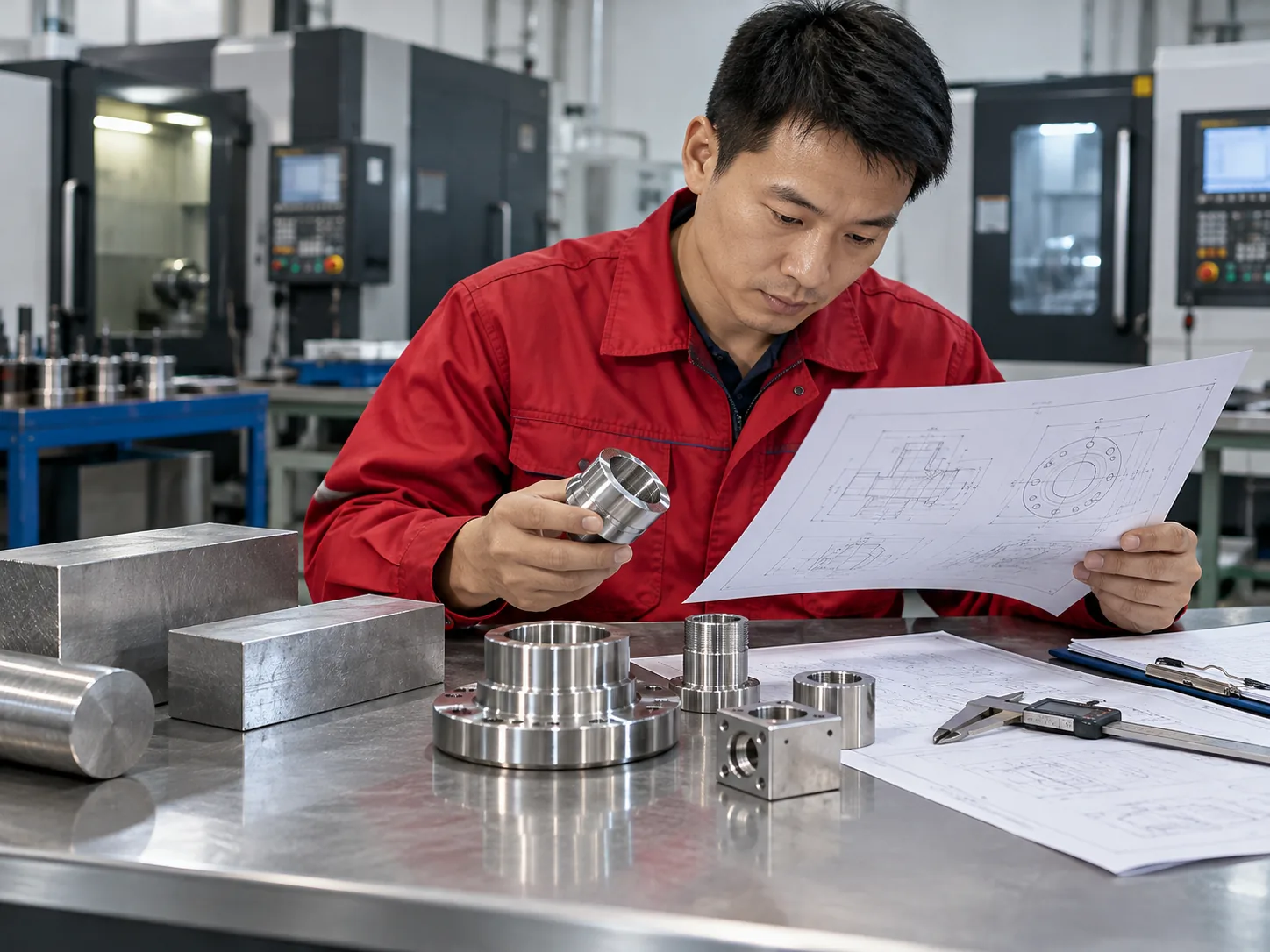
Inspection Follows the Part’s Function
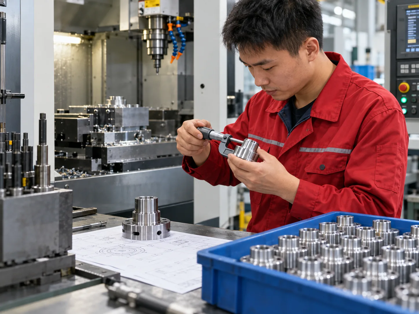
1. Drawing & Material
Confirm the controlled technical version and verify agreed material identity and documentation.
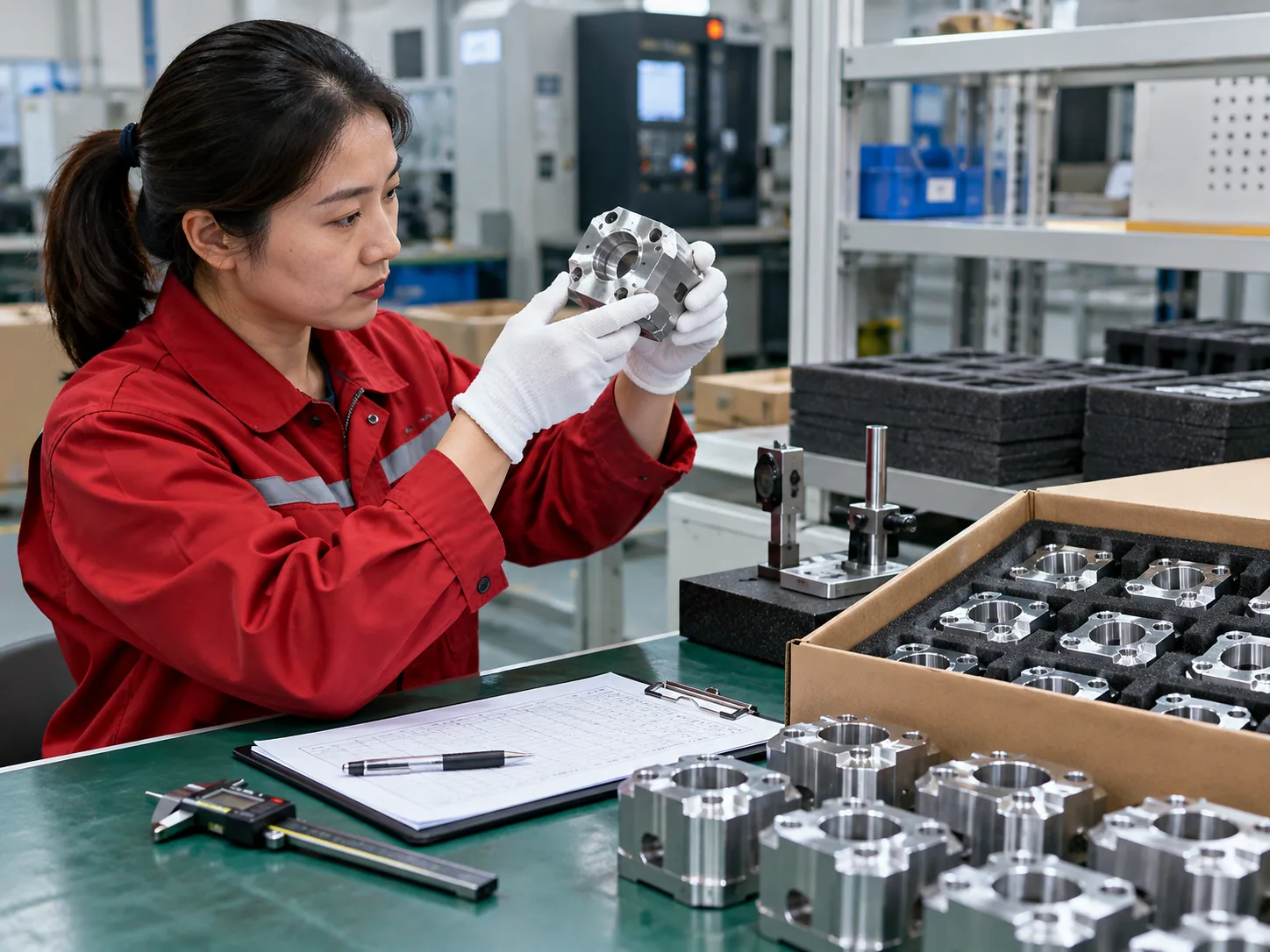
2. In-Process & First Article
Inspect critical sizes/fits, monitor dimensional drift, tool wear, burrs and surface condition.
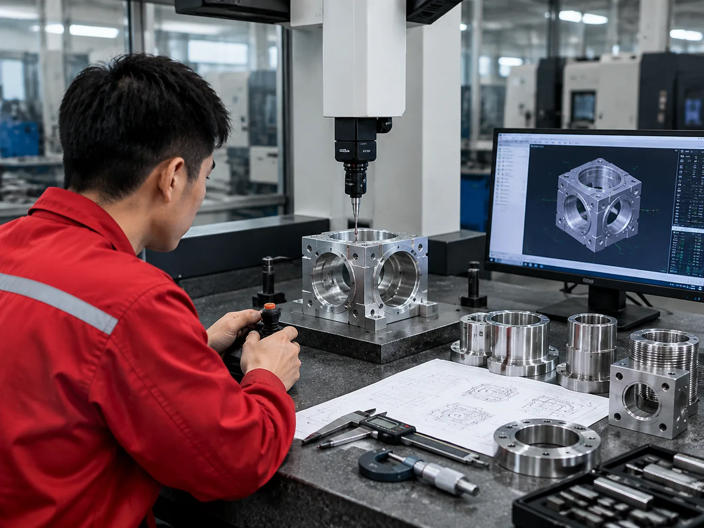
3. Final Verification
Check post-process features, appearance, quantity, packaging and retain project records.
Note: Inspection scope, sampling frequency and reports are project-defined. Possession of measuring equipment does not mean every dimension receives 100% inspection by default.
Choose the Measurement Method for the Feature
| Feature | Typical concern | Suitable inspection direction |
|---|---|---|
| Bearing bore | Size, roundness and relation to mounting face | Bore measurement plus datum-based positional verification as agreed |
| Mounting-hole pattern | Spacing and true position | Optical/CMM or fixture-based verification according to tolerance |
| Flat rail surface | Flatness and parallel relationship | Surface and datum measurement plan |
| Threaded port | Pitch, engagement, entry burr and finish allowance | GO/NO-GO gauge and visual/feature checks where applicable |
| Cross passage | Communication, chips and hidden burrs | Defined cleaning and accessible verification method |
| Cover or enclosure | Opening location and cosmetic surface | Dimensional plus appearance criteria |
The drawing should identify which features affect motion, alignment, sealing, safety or assembly so that inspection effort is placed where it matters.
Move from Sample Validation to Controlled Repeat Orders
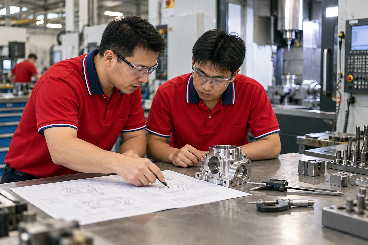
A working sample is the beginning of a production definition, not the end. After approval, the controlled drawing revision, material, machining route, tooling assumptions, critical inspection points and finishing requirements should remain aligned for repeat manufacture.
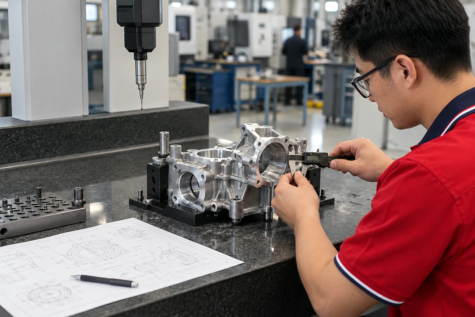
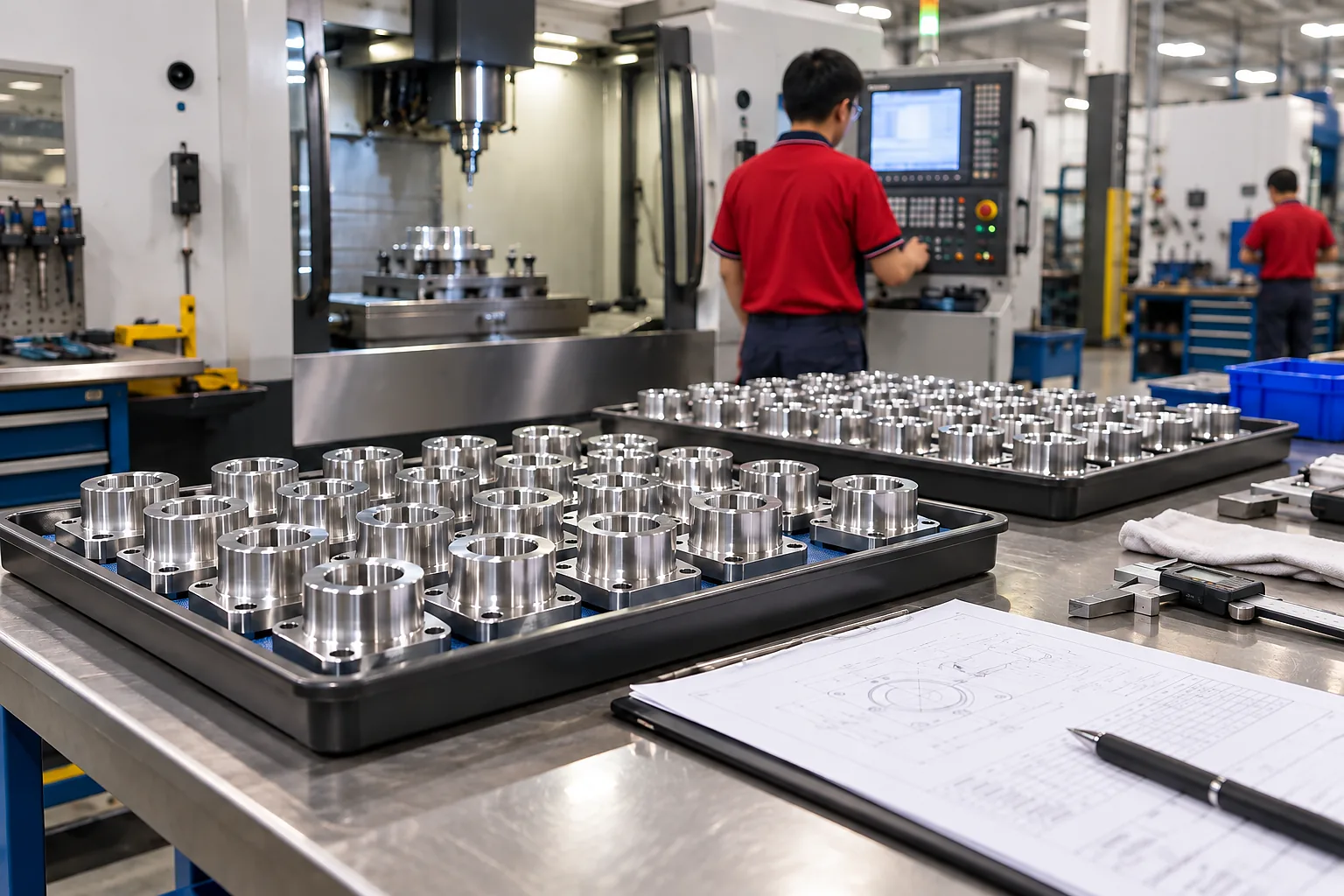
-
1
Technical definitionDrawing, model, material, interfaces and revision
-
2
Manufacturing reviewMachining route, workholding, finish and inspection
-
3
Prototype or first articleConfirm fit, function and measurable characteristics
-
4
Customer validationRecord required corrections and approve the final definition
-
5
Repeat-production transferUse the approved process and critical checks
-
6
Batch and change controlPrevent unapproved revision or requirement drift
Where Custom Milling-Machine Components Are Used
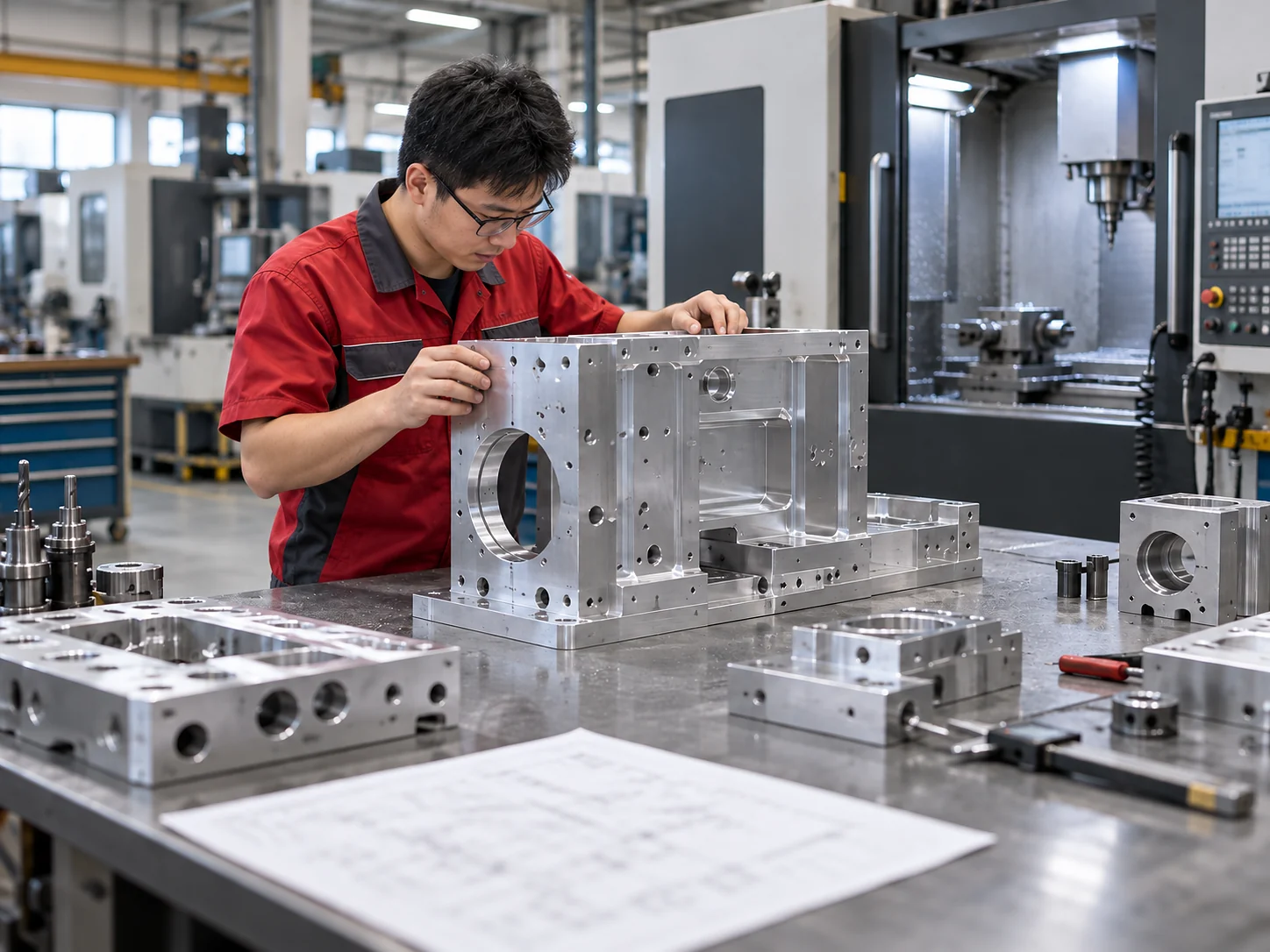
Machine building
Custom mounts, plates, support blocks, enclosures and structural interfaces.
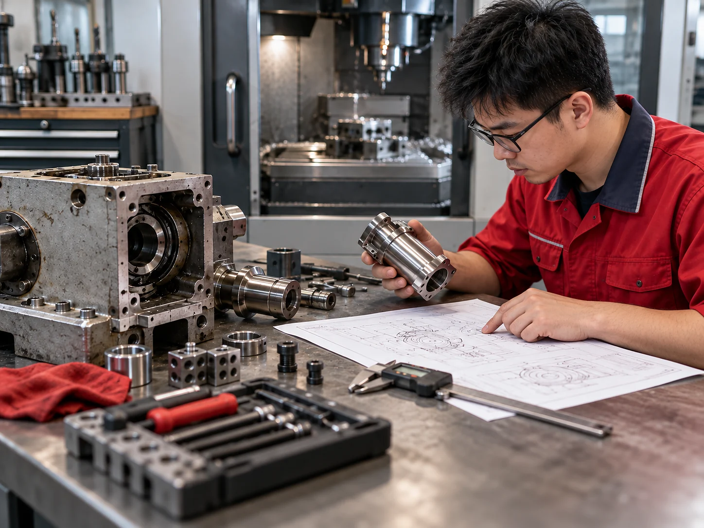
Maintenance and repair
Drawing-defined mechanical components when the original item is unavailable or requires redesign.
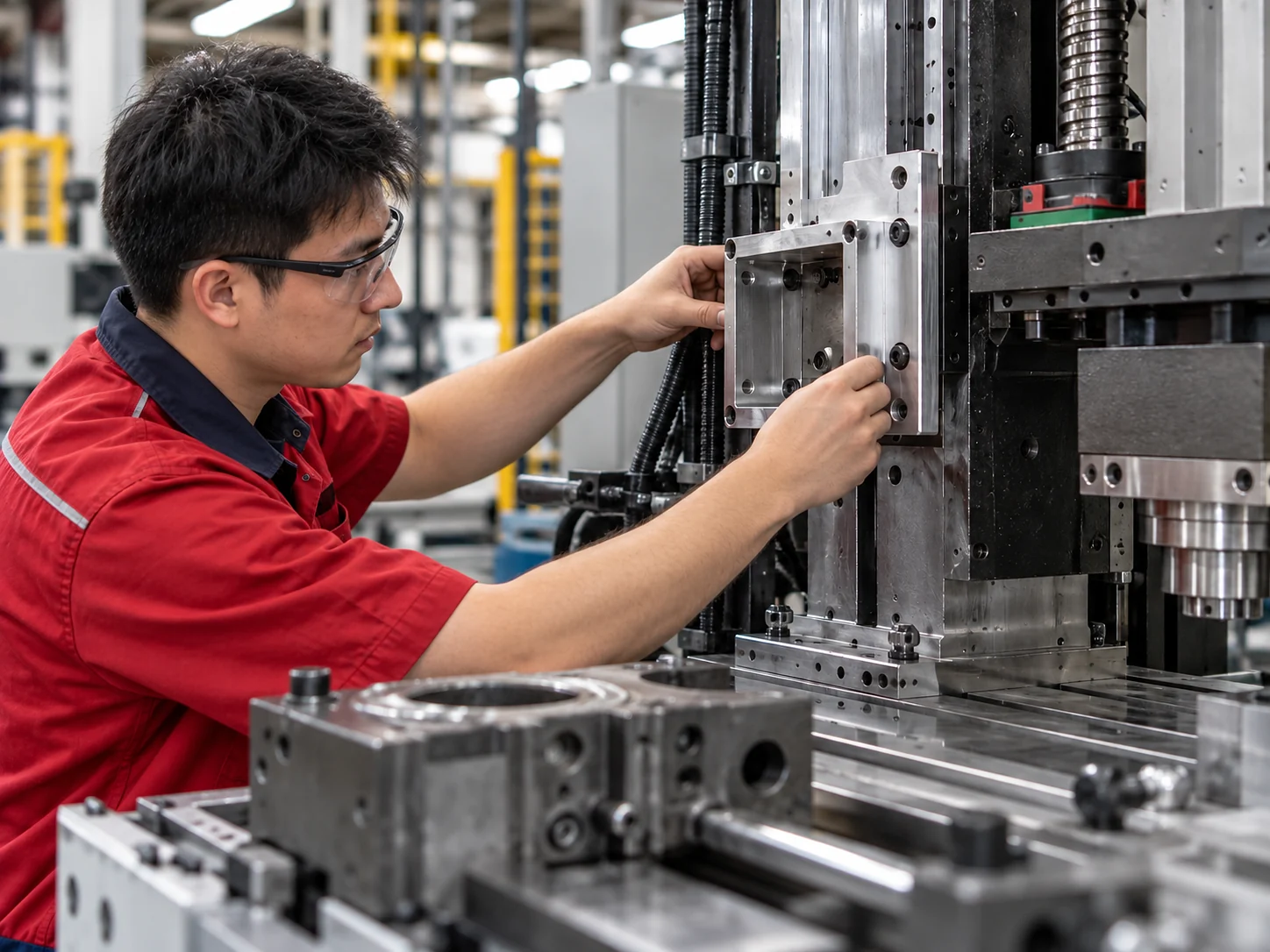
Retrofit projects
Brackets, adapter plates, covers and supports for updated mechanical layouts.
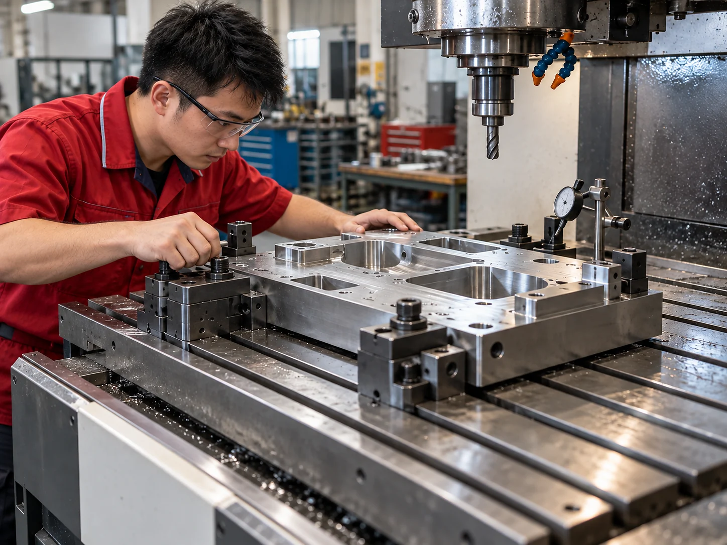
Fixtures and production support
Locating plates, bases, workholding and inspection fixtures.
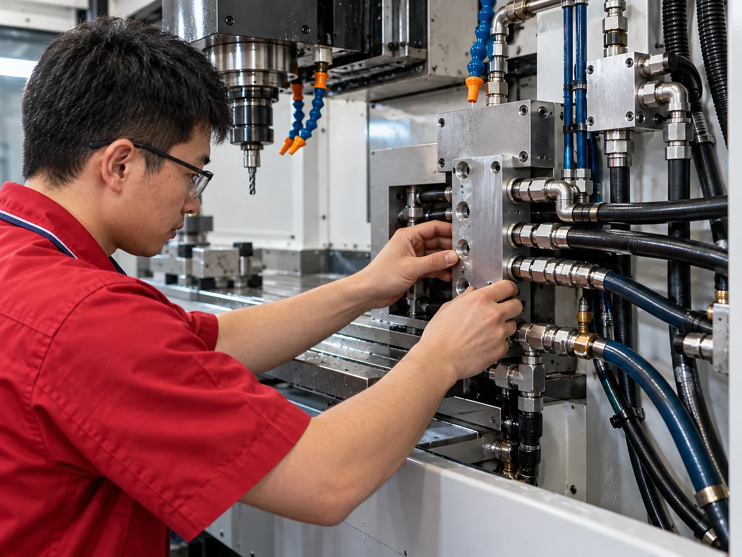
Coolant and lubrication routing
Custom manifolds, port blocks and mounting components.
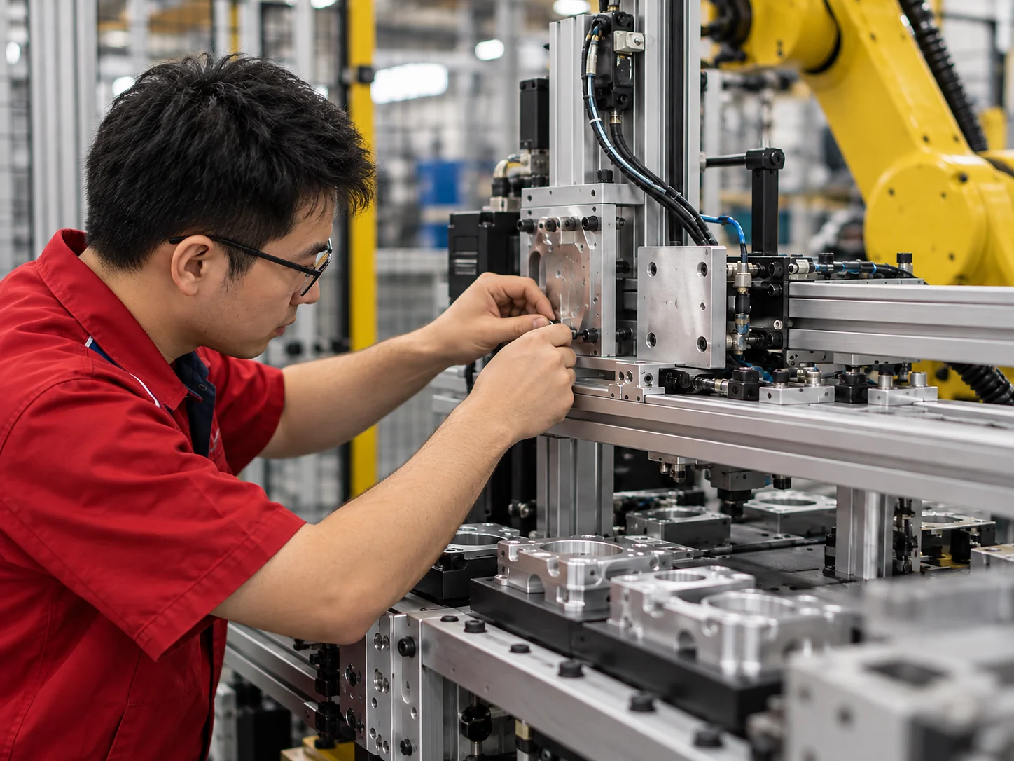
Automation integration
Sensor brackets, motor mounts and interface plates around machine systems.
Boundary: A repair or retrofit component must be assessed within the safety, compatibility and authorization requirements of the complete machine. LuckyHXS manufactures the defined part; the customer or qualified integrator validates the machine-level result.
Why Source Drawing-Defined Components from LuckyHXS
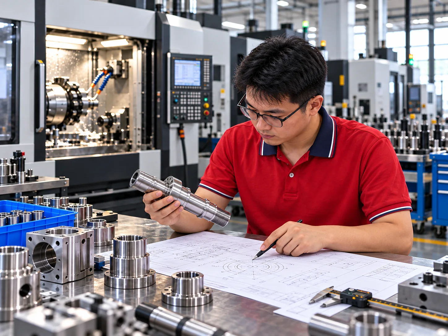
Drawing-first communication
Quotations begin with geometry, material, quantity, critical interfaces and finishing rather than an assumed catalog code.
Multiple machining routes
CNC milling can be coordinated with turning, Swiss or turn-mill operations when the complete geometry requires them.
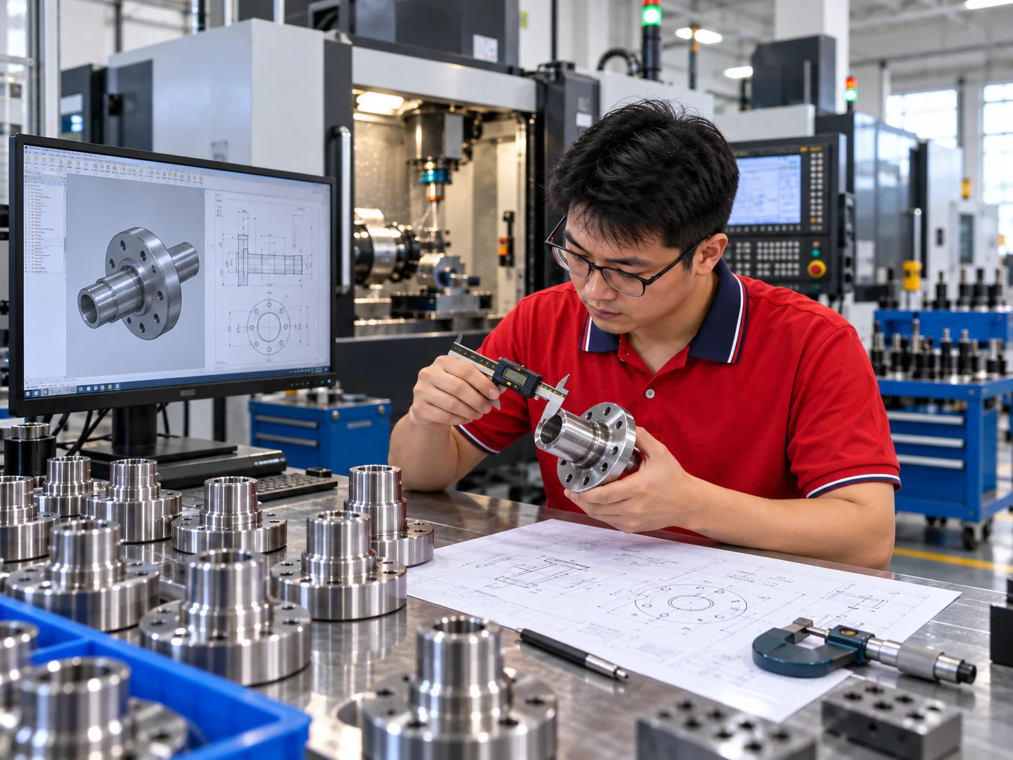
Prototype-to-batch continuity
The project can move from technical review and sample validation into repeat production after approval.
Feature-based inspection
Measurement planning focuses on functional bores, datums, hole patterns, threads, sealing faces and mating surfaces.
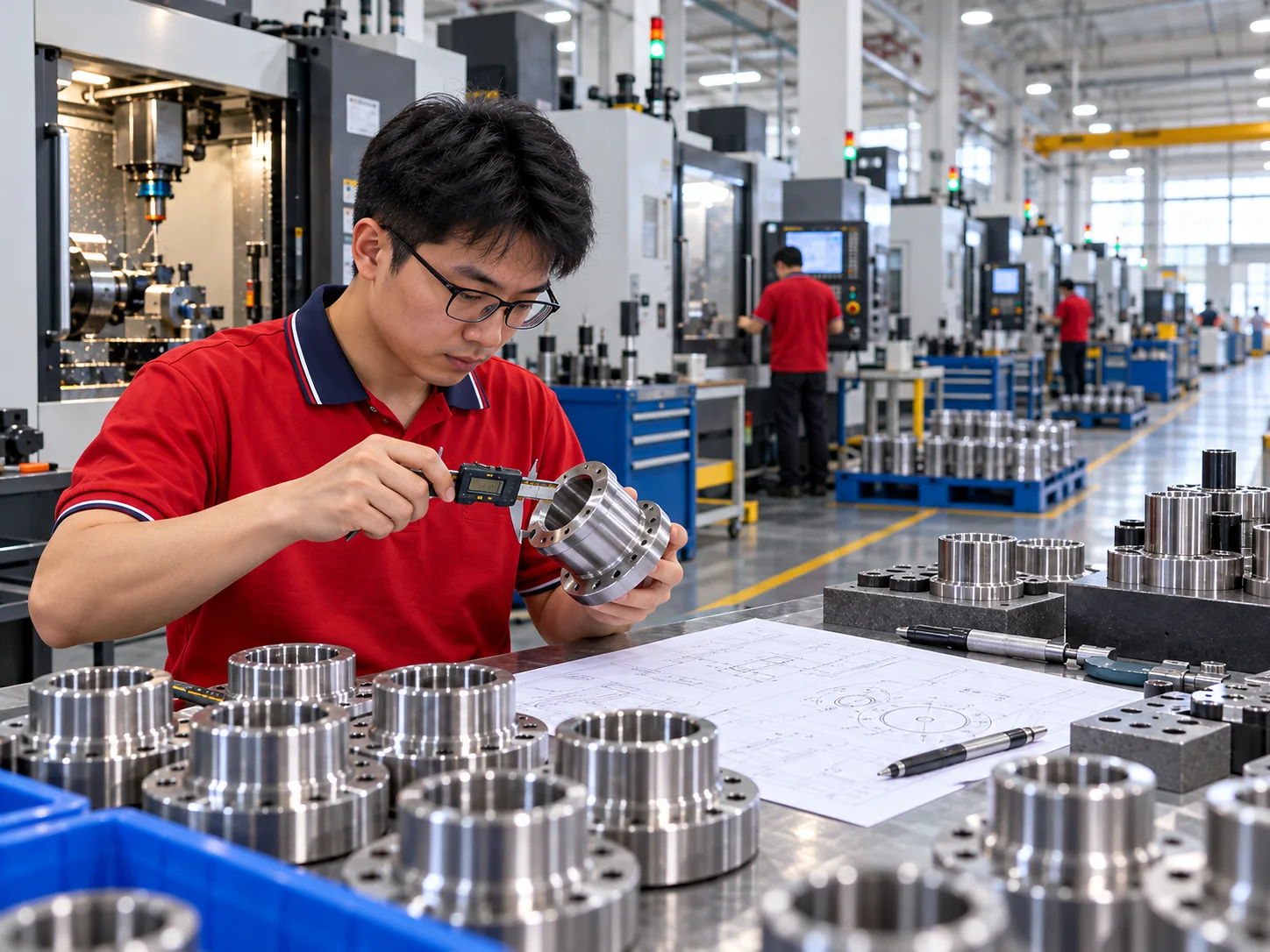
Material and finish coordination
Material grade, masking, coating allowance and post-finish fit are reviewed as connected requirements.
Manufacturing scale
The company operates 153 machining machines with a 160+ person team across approximately 3,100 m²; actual project capacity is confirmed after review.
Manufacturing and Inspection in Shenzhen
LuckyHXS is the precision-machining business of Shenzhen Hong Xiang Sheng Technology Co., Ltd. The team supports custom metal and plastic components from drawing review and sample validation through machining, inspection, coordinated finishing and packaging.
- 20 years of CNC lathe machining experience
- 153 machining machines
- 160+ staff
- Approximately 3,100 m² production and inspection space
- Prototype and repeat-production project support
Quality Management & Available Documentation
ISO 9001, RoHS, REACH, CE and material certificates are available for applicable projects upon technical review.
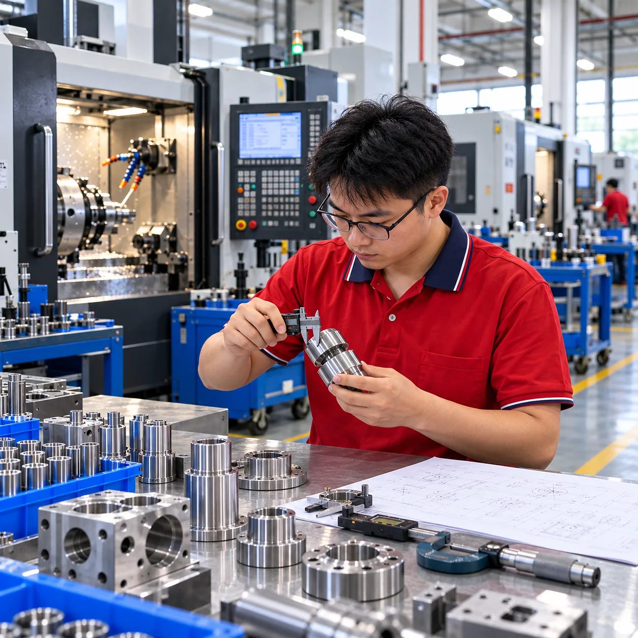
CNC Milling Machine Parts Buyer Guide
Use this guide to distinguish the product you need, prepare a technically useful request and avoid common fit or sourcing mistakes.
Guide Contents
- What are the main parts of a CNC milling machine?
- Are CNC milling machine parts the same as CNC milling parts?
- Can a worn machine part be copied from a sample?
- What information is needed to quote?
- How should tolerances be assigned?
- Which material is best?
- How are dimensions verified after surface treatment?
What are the main parts of a CNC milling machine?
A CNC milling machine combines structural, motion, control, tooling and auxiliary systems. Typical groups include the bed and column, table, spindle structure, guideways, ball-screw drive, motors, feedback devices, tool-changing equipment, coolant and lubrication systems, guarding and the controller.
LuckyHXS does not present every group as a manufactured product. Our scope is the custom mechanical component that can be defined in a drawing, such as a housing, bearing block, plate, bracket, manifold, fixture or cover.
Are CNC milling machine parts the same as CNC milling parts?
No. “CNC milling machine parts” normally means components belonging to the machine. “CNC milling parts” often means customer products manufactured by CNC milling. This page addresses the overlap: custom-machined mechanical components intended for milling equipment, supplied only from a confirmed technical definition.
Can a worn machine part be copied from a sample?
A sample can help establish geometry, but wear, deformation, previous repairs and missing material information can make a direct copy unreliable. Use mating-part data, unworn datums, machine documentation and functional measurements to rebuild the intended definition. Production should proceed from an approved drawing or equivalent controlled specification.
What information is needed to quote a custom machine component?
Provide the controlled 2D drawing and available 3D model, material and condition, target quantity, critical datums and fits, surface finish, inspection requirements and the component’s functional interfaces. For a replacement project, also identify the machine model for context while recognizing that the model name alone does not define compatibility.
How should tolerances be assigned to CNC machine components?
Apply tight tolerances where they control motion, alignment, bearing fit, sealing or assembly. General surfaces and non-functional features should use practical tolerances appropriate to the part. Over-tolerancing every dimension can add setups and inspection effort without improving function. LuckyHXS uses ±0.01 mm only as a general capability reference; each critical feature remains subject to project review.
Which material is best for a milling-machine component?
There is no universal choice. Aluminum can reduce weight and machine efficiently; stainless steel may suit corrosion-sensitive environments; carbon or free-machining steel can fit selected structural and mechanical needs; brass and engineering plastics serve narrower interface, fluid, friction or insulation roles. Load, wear, stiffness, environment, mating materials and finish determine the final grade.
How are replacement-part dimensions verified after surface treatment?
Define whether functional sizes apply before or after treatment. Identify masked areas, coating allowance, threaded features, bearing fits, sealing faces and cosmetic surfaces. Then assign the appropriate post-finish checks. Never assume an as-machined dimension remains unchanged after anodizing, plating, blasting or polishing.
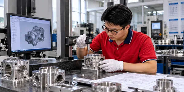
Choose the Right Manufacturing Path
- Explore custom CNC milling parts — for housings, brackets, plates and other components produced by milling, regardless of whether they belong to a machine.
- Review CNC milling services — for process capability, materials and project workflow.
- Compare CNC turning and milling — when the component combines rotational and prismatic geometry.
- Explore aluminum CNC machining — for lightweight housings, plates and brackets.
- Review stainless steel CNC machining — for corrosion-sensitive or stainless interfaces.
- See quality inspection support — for drawing-based inspection and documentation planning.
Prepare a Useful RFQ
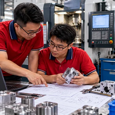
- Controlled drawing revision and available 3D model
- Material grade and heat-treatment condition if applicable
- Quantity for sample and expected repeat orders
- Functional datums, fits and mating components
- Surface treatment and dimensions that apply after finishing
- Inspection, reporting, packaging and traceability requirements
- Machine model and application context, without relying on the model name as the specification
Request a Quote for Custom CNC Milling Machine Parts
Send your drawing, material, quantity, critical interfaces, finish and inspection requirements. We will review whether the requested item fits our made-to-drawing machining scope and identify the technical details needed before quotation.
- Custom mechanical components—not stocked branded assemblies
- Drawing and interface review before manufacturing
- Material, finishing and inspection coordinated by project
- Prototype validation and repeat-production support where appropriate