
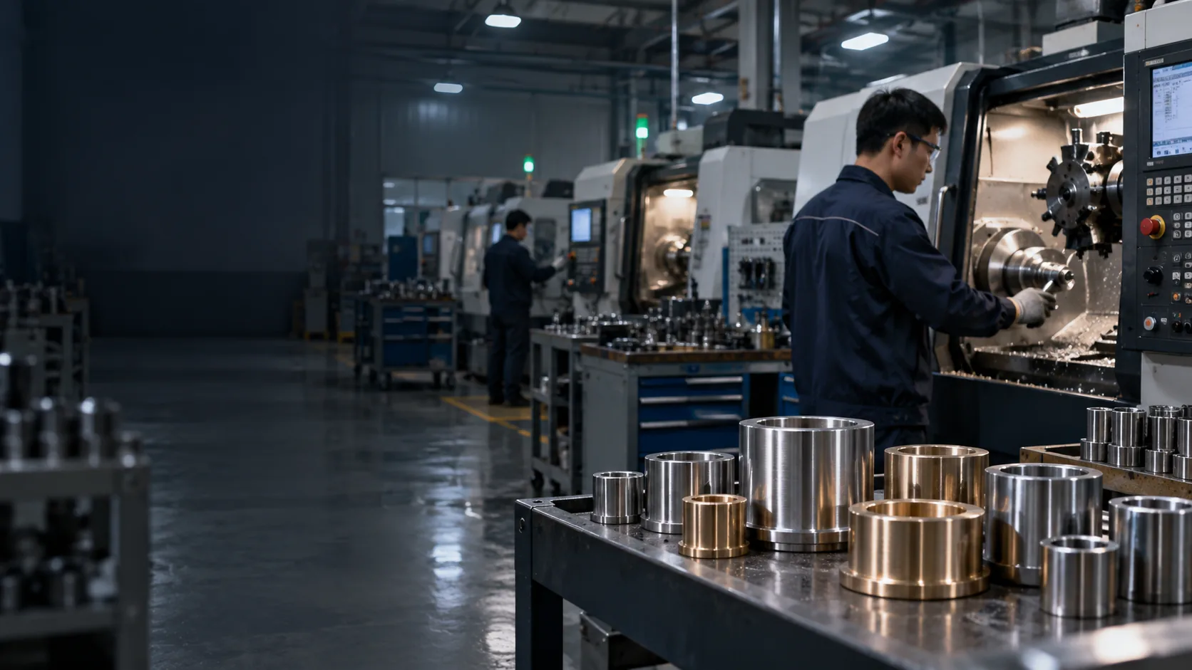
Custom CNC Machined
Bushings Built to
Your Drawings
LuckyHxs manufactures custom bushings according to your 2D/3D drawings, ID/OD, material, fit, flange, groove, and application requirements.
- Made to Your Drawing
- ID / OD & Fit Review
- CNC Turning / Swiss / Turn-Mill Support
- Prototype to Repeat Production
Custom Bushings at a Glance
What Makes a Bushing "Custom"?
Custom manufacturing isn't just about changing the inner or outer diameter. When off-the-shelf standard bearings don't fit your assembly, a custom CNC bushing is machined to incorporate specific geometric and functional features.
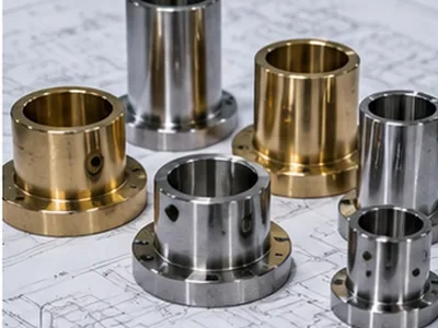
A true custom bushing may include specific flange dimensions for axial positioning, multiple steps to bridge transition diameters, retaining grooves, lubrication holes, controlled wall thickness for precise press fits, or non-standard materials selected for unique wear environments.
Standard vs Custom CNC Bushing
- Standard: Fixed ID/OD catalog sizes, generic material grades, assumed clearances.
- Custom: Machined specifically to your drawing's tolerance, fit requirement, and surface finish callouts.
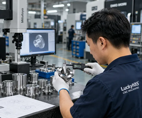
Need Made-to-Drawing Bushings, Not Standard Stock Sizes?
LuckyHxs is a custom manufacturer, not a retail bearing distributor. We partner with OEM buyers, mechanical engineers, and equipment manufacturers who require custom dimensions, specific materials, controlled fits, and reliable prototype-to-production scalability.
Custom Bushing Types We Manufacture to Drawing Requirements
Geometry defines how the bushing fits and functions within the assembly. Material defines wear, corrosion resistance, and operating characteristics.
By Bushing Geometry
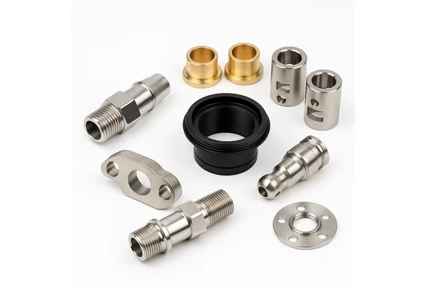
Custom Flanged Bushings
Features a flange for axial location and installation stops. Critical controls include flange thickness and flange-to-bore squareness.
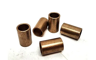
CNC Machined Custom Sleeve Bushings
Straight OD and precision bore for shaft support, guide sleeves, and rotating assemblies. We focus on bore-to-OD concentricity and edge condition.
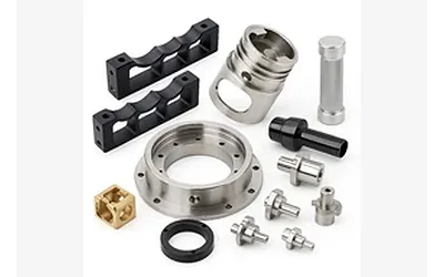
Custom Stepped Bushings
Multi-step OD or stepped ID for non-standard assemblies and positioning. Requires strict control of step position and concentricity.
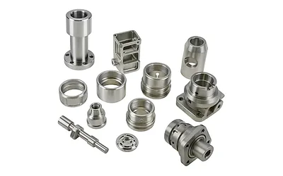
Custom Threaded Bushings
Internal or external threads for adjustable or adapter applications. Inspected for thread pitch, concentricity, and burr-free edges.
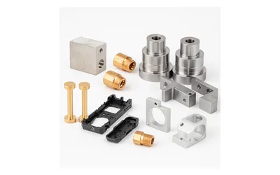
Custom Thin Wall Bushings
Requires specialized workholding and cutting sequences to prevent clamping distortion and ensure post-machining dimensional stability.
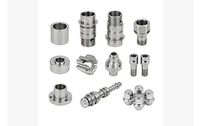
Custom Grooved Bushings
Includes lubrication distribution, retaining, or circlip grooves. Machined with strict attention to groove width, depth, and position.
Popular Material Options
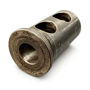
Custom Bronze Bushings
Selected for wear surfaces, sliding motion, and low-speed mechanical movement. Grade and lubrication requirements are reviewed per drawing.
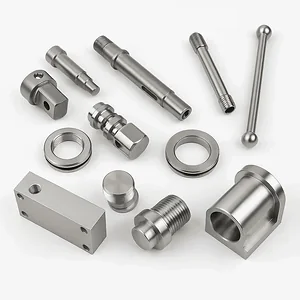
Custom Stainless Steel Bushings
Ideal for corrosive environments, automation equipment, and clean assemblies. Material grade availability is confirmed during quotation.
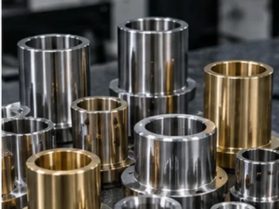
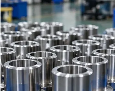
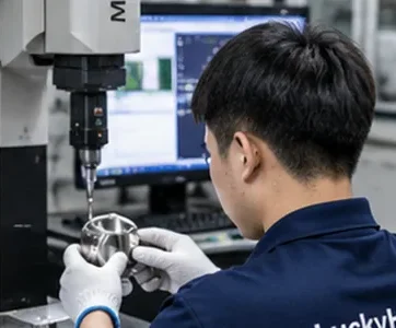
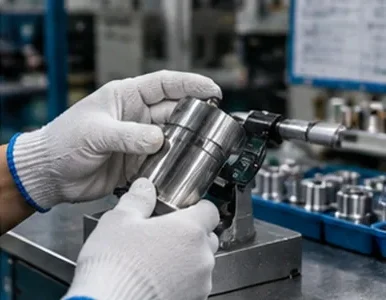
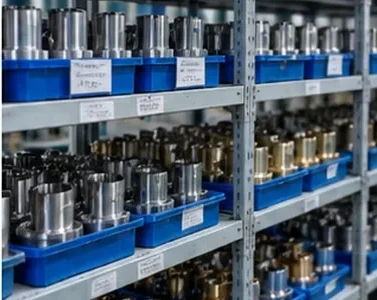
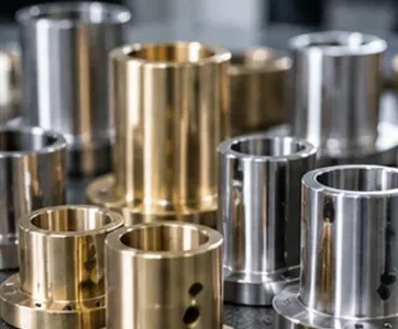
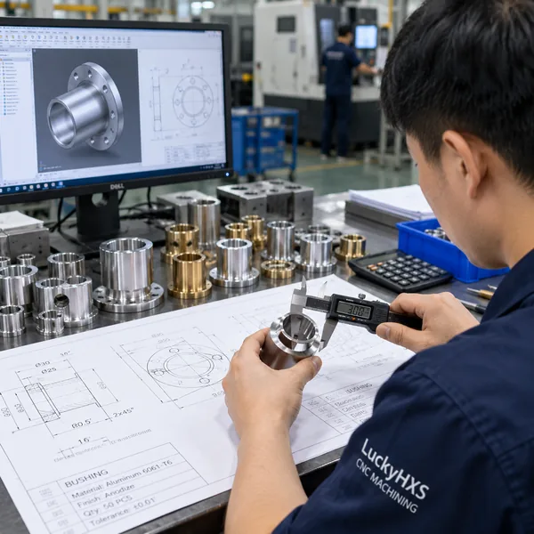
CNC Machined Bushing Structures for Custom Assemblies
What Should You Specify on a Custom Bushing Drawing?
To ensure the final machined component functions correctly in your assembly, providing clear specifications is critical. Our engineering team reviews these details before quotation.
Why Simple-Looking Bushings Cause Expensive Assembly Problems
A bushing may look simple, but improper machining control can lead to failure during installation or operation. Here are the risks we review before production.
1. ID / OD Tolerance Inconsistency
Free-state dimensions may pass, but installed fit fails due to tolerance stack or incorrect interference assumptions.
2. Poor Concentricity
Bore and OD machined in different setups cause shaft runout, vibration, and uneven wear.
3. Incorrect Press/Slip Fit
Bushing spins inside the housing or clamps too tightly on the shaft after installation.
4. Rough Bore Surface
Improper boring feeds leave tool marks that rapidly wear down expensive mating shafts.
5. Burrs & Sharp Edges
Inconsistent deburring damages housing bores during press fitting or scores the shaft.
6. Prototype-to-Batch Gaps
First samples fit perfectly, but tool wear and setup changes cause mass production parts to drift.
1. ID / OD & Fit Don’t Match the Assembly
The Challenge
A bushing may measure correctly in isolation, but once installed, the bore is too tight for the shaft, or the OD is too loose for the housing, causing excessive friction or vibration. Free-state dimensions and installed fit are not always the same thing.
Why It Happens
Tolerance stack-up, incorrect interference allowances, variation in the housing bore, or press-fit deformation (where the ID shrinks when the OD is compressed) are often not considered in the drawing assumptions.
LuckyHxs Approach
We review ID and OD together. Where necessary, we ask for mating shaft and housing bore information to confirm the intended press fit, slip fit, or clearance requirement before machining.
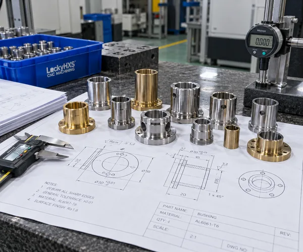
What We Check
- • ID & OD
- • Roundness (where required)
- • Wall thickness
- • Housing-related fit
- • Shaft-related fit
- • Chamfer angles
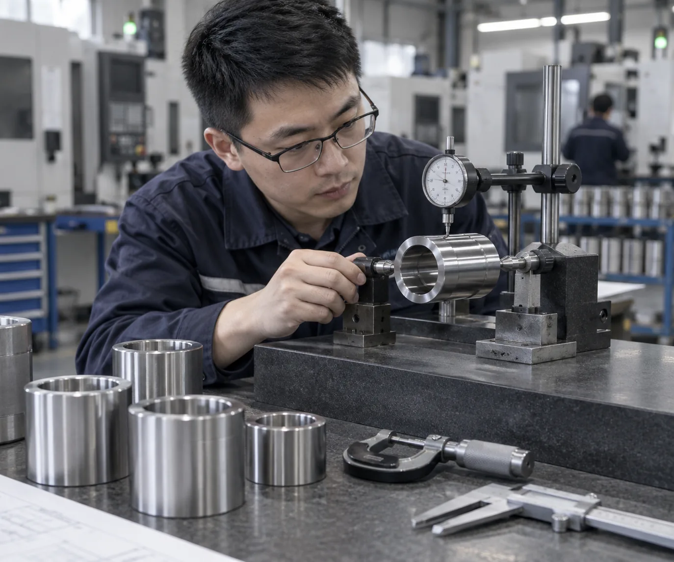
2. Bore-to-OD Concentricity Drifts
The Challenge
The ID and OD may both pass individual diameter checks, but if they are not concentric, the shaft will experience runout, uneven clearance, vibration, and premature wear on one side.
Why It Happens
Repeated clamping, changes in datums between boring and turning setups, tool deflection, unstable workholding on thin-wall parts, or improper cutting sequences.
LuckyHxs Approach
We establish a clear machining datum strategy. Where practical, related cylindrical features are machined in controlled, single setups. Feature-specific concentricity requirements are reviewed directly from your drawing.
What We Check
- • ID to OD Concentricity
- • Runout (where specified)
- • Roundness
- • Shoulder face relationship
3. Sample-to-Batch Fit Changes
The Challenge
Prototype Fits → Production Batch Drifts. The ID gradually changes, fits become inconsistently tight or loose, flange thickness varies, or burr removal becomes irregular across a large run.
Why It Happens
Tool wear over hundreds of cycles, bar material variation, fixture/collet changes, operator differences, or a lack of revision control and in-process monitoring.
LuckyHxs Approach
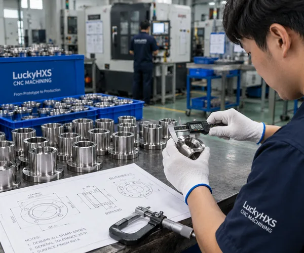
We rely on first-article verification, identify critical ID/OD dimensions for in-process checks, monitor tool wear, and retain production requirements to ensure repeat batches match the approved prototype.
What We Check
- • Repeat-batch consistency
- • Critical length & flange
- • Bore & edge condition
- • Grooves & threads stability
Other Bushing Risks Worth Reviewing Before Production
7. Thin-Wall Distortion
Out-of-round bores caused by clamping forces during machining.
Review: Workholding strategy
8. Groove Position Errors
Misaligned oil holes or retaining grooves blocking lubrication.
Review: Datum references
9. Flange/Length Error
Incorrect axial positioning within the housing assembly.
Review: Shoulder position
10. Material Mismatch
Selecting the wrong grade for specific wear or corrosion conditions.
Review: Operating environment
Design the Bushing Around the Actual Shaft and Housing Fit
Press Fit Considerations
Requires controlled interference between the bushing OD and housing to retain the part and prevent spinning. The installed ID will often shrink based on wall thickness and housing material. This must be calculated.
Slip Fit Considerations
Requires controlled clearance for easy installation, removal, or adjustment. However, excessive clearance leads to movement, vibration, and poor alignment.
Do Not Specify the Bushing Diameter Alone
For fit-critical projects, consider the Bushing + Shaft + Housing as one complete assembly system. The drawing should reflect final required clearance, installation method, and material behavior.
Choose Bushing Material Around Wear, Fit and Environment
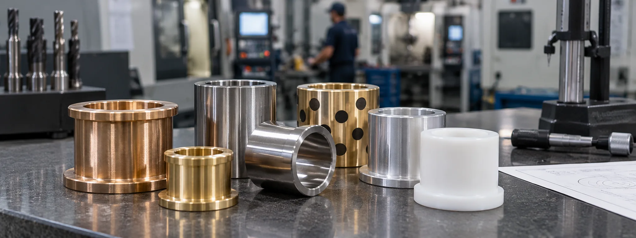
Material selection must be based on load, speed, shaft material, lubrication, temperature, and lifecycle requirements.
Bronze
Selected for wear and sliding applications according to specific grade and lubrication requirements.
Stainless Steel
Provides corrosion resistance for mechanical equipment and precision assemblies.
Brass
Offers excellent machinability for instruments, fittings, and selected sliding applications.
Free-Machining Steel
Cost-efficient for machined structural bushings requiring specific surface finishes.
Aluminum
Lightweight option for custom bushings where the application load allows.
Engineering Plastics
Used for selected low-friction, electrical insulation, or lightweight requirements.
Machining Features for Custom Bushings
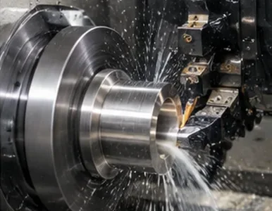
The choice between CNC Turning, Swiss Machining, Automatic Lathe, or Turn-Mill depends on geometry, diameter, length, quantity, and specific features.
Inspect the Dimensions That Control Real Assembly Fit
- 1. Drawing Review
- 2. Material Confirmation
- 3. Fit Requirement Review
- 4. First Article Verification
- 5. In-Process ID / OD Checks
- 6. Groove / Thread Inspection
- 7. Bore & Burr Review
- 8. Final Inspection
- 9. Batch Identification / Documentation as Required
Key Inspection Focus:
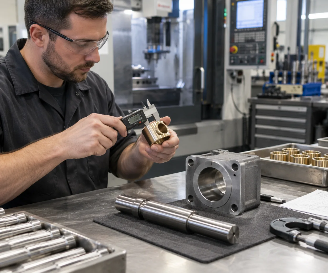
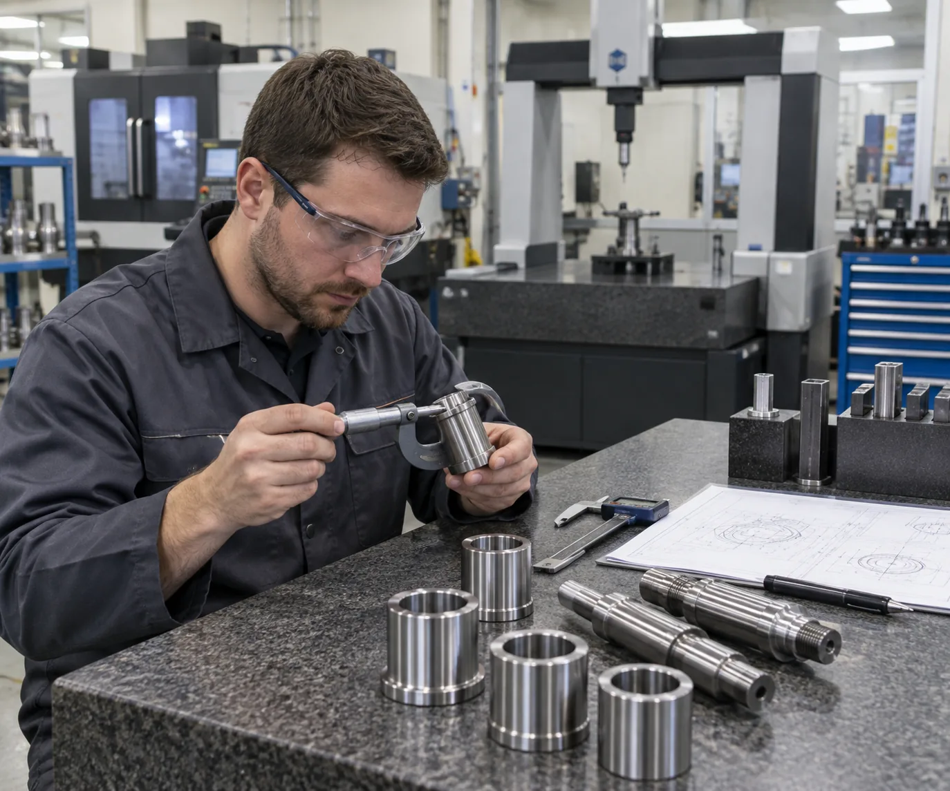
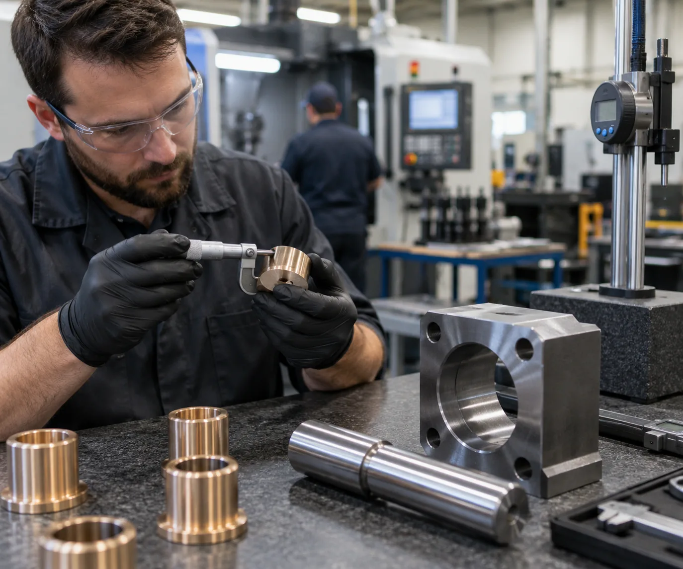
ID, OD, length, flange thickness, bore condition, concentricity, runout (where required), threads, grooves, burrs, and overall surface condition using appropriate inspection equipment.
Where Custom CNC Bushings Are Used
Industrial Automation
Typical: Flanged Guide Bushings
Function: Positioning and linear guidance.
Watch Point: Bore concentricity
Robotics
Typical: Thin Wall Bushings
Function: Lightweight joint rotation.
Watch Point: Clamping distortion
Automotive & EV
Typical: Stepped Sleeve Bushings
Function: Component spacing and alignment.
Watch Point: Batch fit consistency
Industrial Machinery
Typical: Custom Bronze Bushings
Function: Heavy load sliding wear surfaces.
Watch Point: Lubrication grooves
Pumps & Fluid Equip.
Typical: Stainless Steel Bushings
Function: Shaft support in corrosive media.
Watch Point: Material grade
Precision Instruments
Typical: Threaded Adapter Bushings
Function: Fine adjustment and mounting.
Watch Point: Thread concentricity
Tooling & Fixtures
Typical: Hardened Sleeve Bushings
Function: Drill guiding and locating.
Watch Point: Press fit tolerance
Construction Equip.
Typical: Large Flanged Bushings
Function: Pivot point wear protection.
Watch Point: Flange thickness
A CNC Manufacturing Partner You Can Verify
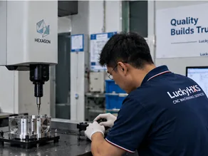
See Custom Bushing Machining in Our Factory
What Is a Bushing and What Does It Do?
A bushing is typically a cylindrical component located between a shaft or pin and a housing or supporting structure. Its primary purposes include guiding movement, reducing wear, providing a replaceable wear surface, controlling clearance, and supporting shafts to reduce direct contact between expensive components.
Common Bushing Types
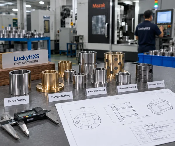
Sleeve, Flanged, Stepped, Threaded, Grooved, and Thin Wall.
What Information Does a Custom Bushing Manufacturer Need?
- • ID, OD, Length
- • Material
- • Shaft size & Housing bore
- • Fit type
- • Flange & Groove details
- • Lubrication requirement
- • Surface finish & Quantity
Bushing vs Bearing: What’s the Difference?
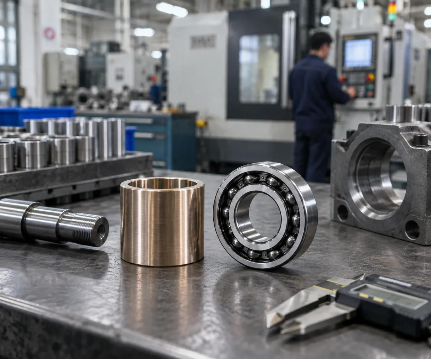
"Bearing" is a broad category of components that support motion. A bushing typically falls under the plain or sliding bearing concept.
When Should Buyers Ask for a Custom CNC Bushing?
When you need non-standard ID/OD, a custom flange, special grooves, unusual materials, custom fits, stepped geometry, low-volume prototypes, or repeat OEM production.
Press Fit vs Slip Fit Bushings: How Do You Choose the Right Fit?
Press Fit
Requires controlled interference between the bushing OD and housing to retain the bushing, reduce movement, and avoid spinning. Must consider material, OD, wall thickness, housing material, and final installed ID.
Slip Fit
Provides controlled clearance for easy installation, removal, adjustment, and replaceable arrangements. However, an overly loose fit may cause movement, vibration, and poor alignment.
What Should Be on the Drawing?
- • Bushing OD & Housing bore
- • Shaft diameter
- • Final required clearance
- • Tolerance class (if specified)
- • Material & Wall thickness
- • Installation method
Frequently Asked Questions About Custom Bushings
Can you manufacture custom bushings from our drawings?
What is the difference between a sleeve bushing and a flanged bushing?
What is the difference between a press-fit and slip-fit bushing?
What materials can be used for custom bushings?
How do you control ID / OD and concentricity?
Can you machine oil grooves, circlip grooves and lubrication holes?
Can you manufacture thin-wall bushings?
What information do you need for a custom bushing quotation?
Need a Bushing That Actually Fits the Shaft and Housing?
Send your 2D/3D drawing, key dimensions, material, quantity, and inspection needs. We’ll evaluate critical specs and machining process before quoting.
What We Review Before Quotation
ID / OD & Fit Relationship
We review shaft diameter, housing bore, clearance or interference fit, and functional tolerance relationships.
Flange, Groove & Shoulder Features
Critical locating faces, flange thickness, grooves and shoulders are checked against the intended assembly.
Material & Machining Route
Material, quantity and geometry are reviewed to select CNC turning, Swiss machining or turn-mill production.
Inspection Requirements
Critical ID, OD, concentricity, runout and fit-related dimensions are identified before production.