


Background Texture
Made to Your Drawing

Custom CNC Machined Brackets for Precision Mounting & Alignment

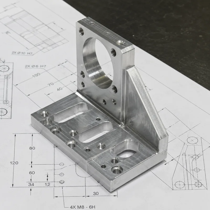
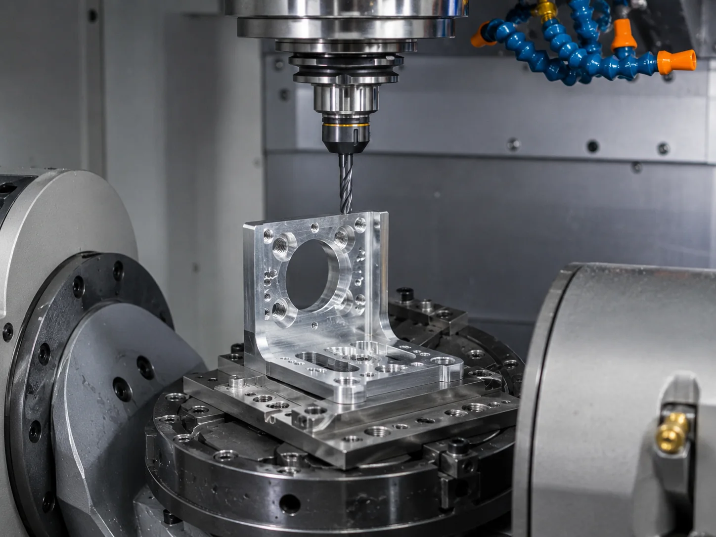
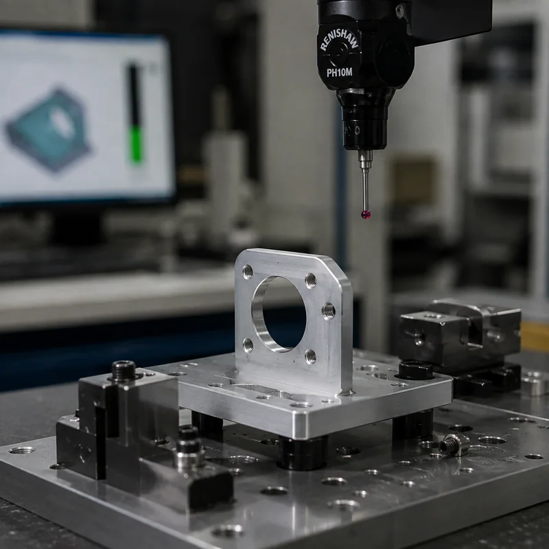
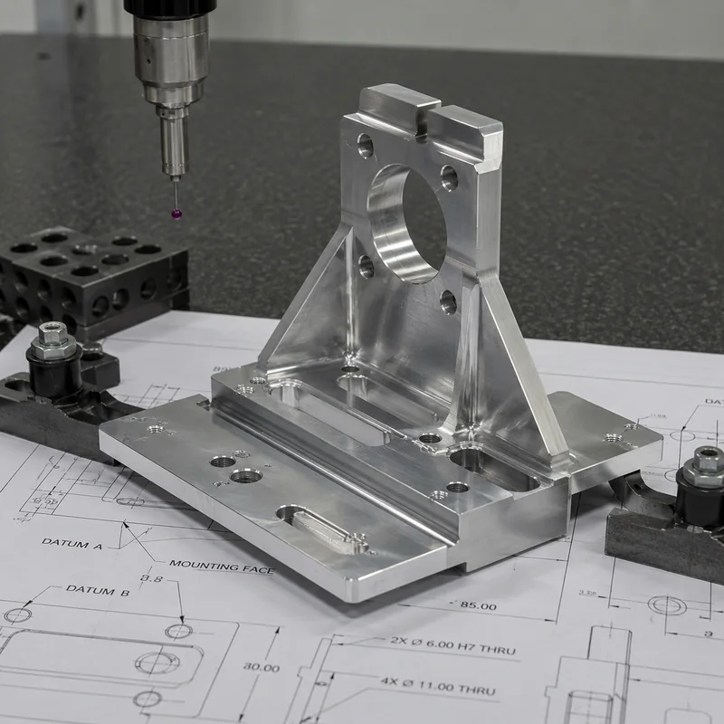
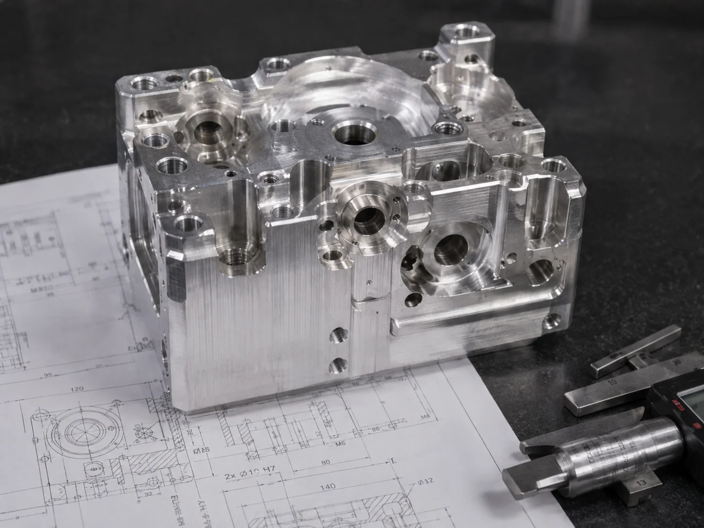
LuckyHxs manufactures custom CNC machined brackets from customer drawings for motors, sensors, robotics, automation, electronics and industrial equipment. Our machining focuses on mounting datums, hole patterns, locating features, flatness and multi-surface relationships so the complete bracket fits the assembly—not just the individual dimensions.

20+ Years CNC Experience
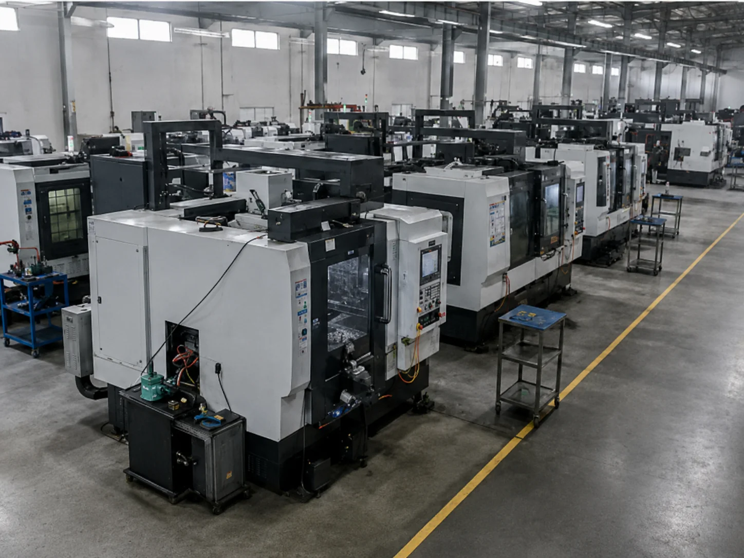
153 Precision Machines
Standard Ref ±0.01 mm
Prototype to Batch
Discuss Mounting Requirements
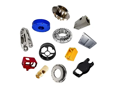
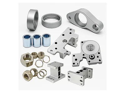
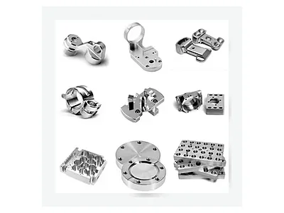
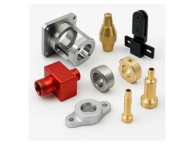
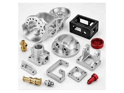
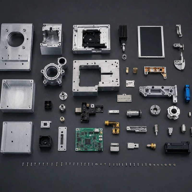
Collection of Custom CNC Machined Brackets

Engineering Focus

Multi-Surface Machining

Custom Machined Brackets at a Glance

Manufacturing Specs

  • Supply Type: Custom Made-to-Drawing
  • Processes: CNC Milling / 5-Axis / Drilling / Boring
  • Tolerance: Standard Ref ±0.01 mm
  • Materials: Aluminum / Stainless / Steel / Brass

Engineering Focus

  • Critical Features: Hole Pattern / Datum / Dowel
  • Geometry Control: Flatness / Perpendicularity
  • Drawing Inputs: PDF, STEP, STP, IGES
  • Volume: Prototype to Repeat Production
Feature-specific capability depends on bracket size, material, geometry, wall thickness, tolerance and inspection requirements.

Looking for a custom precision mounting bracket?

Rather than an off-the-shelf or sheet-metal support? Send the drawing and mating requirements for machining review.

What Makes a Machined Bracket Different From a Simple Support?

A generic bracket simply carries weight. A precision CNC machined bracket acts as a functional interface that controls the exact spatial relationship between two assemblies.

1

Support & Mount

Provides a rigid base, but relies on machined flatness to prevent assembly distortion.

2

Locate & Center

Utilizes precision dowel holes and pilot bores to determine exact, repeatable position.

3

Align & Orient

Uses perpendicular mounting faces to control angular orientation of sensors or motors.

The more a bracket controls position, alignment and mating geometry, the more important its datum relationships become.

Machined Bracket Functional Zones

CNC Machined Brackets We Manufacture to Your Drawings

Classified by what they mount and the critical features that control the assembly.

Precision Equipment Mounting Brackets

Equipment Mounting Brackets

Base plates and support interfaces requiring precise hole patterns relative to a mounting datum.

Watch: Hole Pattern True Position
Motor & Actuator Mounting Brackets

Motor & Actuator Brackets

Servo and stepper motor mounts where the pilot bore and bolt pattern function as one geometry.

Watch: Pilot-to-Bolt Relationship
Sensor & Instrument Mounting Brackets

Sensor & Instrument Brackets

Mounts for probes and encoders where angular alignment and repeatable position are critical.

Watch: Angular Alignment
Robotics & Automation Brackets

Robotics & Automation Brackets

End-effector and linear motion mounts requiring exact cross-face datum relationships.

Watch: Cross-Face Perpendicularity
Camera & Optical Brackets

Camera & Optical Brackets

Machine vision and lens mounts acting as alignment components, not just simple supports.

Watch: Optical Axis Position
Electronic & Control Module Brackets

Electronic & Control Brackets

Machined aluminum interfaces with pockets, bosses, and heat contact surfaces for ECUs.

Watch: Flatness & Connector Alignment
Automotive & EV Equipment Brackets

Automotive & EV Equipment

Precision mounts for motors, sensors, and electrical equipment requiring batch repeatability.

Watch: Batch Repeatability
Complex Multi-Surface Brackets

Complex Multi-Surface Brackets

Multi-datum components requiring coordinated multi-axis machining for angled faces.

Watch: Datum Transfer Error

Precision Mounting Brackets for Industrial Assemblies

MOUNT → Equipment Bracket CENTER → Motor Pilot Bracket ALIGN → Sensor / Camera Bracket LOCATE → Dowel Bracket ADJUST → Slotted Bracket CONNECT → Interface Bracket
Equipment Bracket Equipment Support Bracket Motor Mounting Bracket Actuator Bracket Sensor Mount Instrument Bracket Robotics Interface Bracket Optical Camera Bracket Electronics Control Bracket EV Equipment Bracket Complex Multi-Surface Bracket 1 Complex Multi-Surface Bracket 2

Choose Bracket Material Around Weight, Stiffness & Interface Requirements

Material selection impacts machinability, thin-wall stability, and final finish fit.

Aluminum

6061 / 6063 / 6082 / 7075

  • Typical: Equipment, Motor, Sensor, Robotics, Camera, EV
  • Why: Lightweight, highly machinable, suitable for complex pockets.
Watch: Thin-wall distortion, flatness after unclamping, anodizing allowance.

Stainless Steel

303 / 304 / 316 / 316L

  • Typical: Industrial Mounts, Corrosion-sensitive environments.
  • Why: High strength, natural corrosion resistance without plating.
Watch: Machining load, thread tapping quality, weight constraints.

Steel & Project-Specific

Free-Machining Steel / Brass / Titanium

  • Steel: Equipment supports (Watch: Corrosion protection).
  • Brass: Electrical/Connector specific.
  • Titanium: Titanium bracket machining projects reviewed per geometry and application.
CNC Machining Process Selection for Brackets

How Are Precision Machined Brackets Manufactured?

The goal is not to use the most complex machine—the goal is to keep the critical mounting relationships under control efficiently.

Simple Open Bracket → 3-Axis CNC Milling

Suitable for open pockets, top-face holes, and standard profiles where all critical features are on one plane.

Multi-Sided Bracket → Indexed / Multi-Axis Machining

Required for side holes, multiple mounting faces, and cross-face features to reduce setup transfers.

Complex Angled Bracket → 5-Axis Evaluation

Selected for angled faces, hard-to-reach holes, and complex datum orientations where re-clamping would destroy tolerance.

Round + Milled Features → Turn-Mill Evaluation

Where rotational pilot features dictate the primary datum.

Why Machined Brackets Fail Even When Individual Dimensions Pass

01

Hole Patterns Pass Individually but Lose Functional Datum Position

02

Mounting Faces Lose Flatness or Perpendicularity

03

Prototype Passes, but Mounting Geometry Drifts in Production

04

Multi-Surface Features Lose Their Cross-Face Alignment

05

Thin-Wall & Pocketed Brackets Warp After Machining

06

Pilot Bores & Bolt Patterns Pass but Mounted Axis Is Misaligned

07

Threaded Holes Pass Gauging but Fail Fastener Assembly

08

Slots & Adjustment Features Pass Size Checks but Fail Functional Range

09

Anodizing or Coating Changes Critical Bracket Interfaces

10

Burrs, Sharp Edges & Clamp Marks Damage Functional Interfaces

Core Challenge 01

Hole Patterns Pass Individually but Lose Their Functional Datum Position

Hole A Size: PASS
Hole B Size: PASS
Hole C Size: PASS
Pattern-to-Datum: FAIL

Result: Fasteners cannot enter, dowels do not align, or sensor position shifts.

Hole Diameter PASS ≠ Mounting Pattern PASS

The LuckyHxs Approach

  • Review primary mounting datum and locating holes/dowels.
  • Plan machining sequence around functional datums.
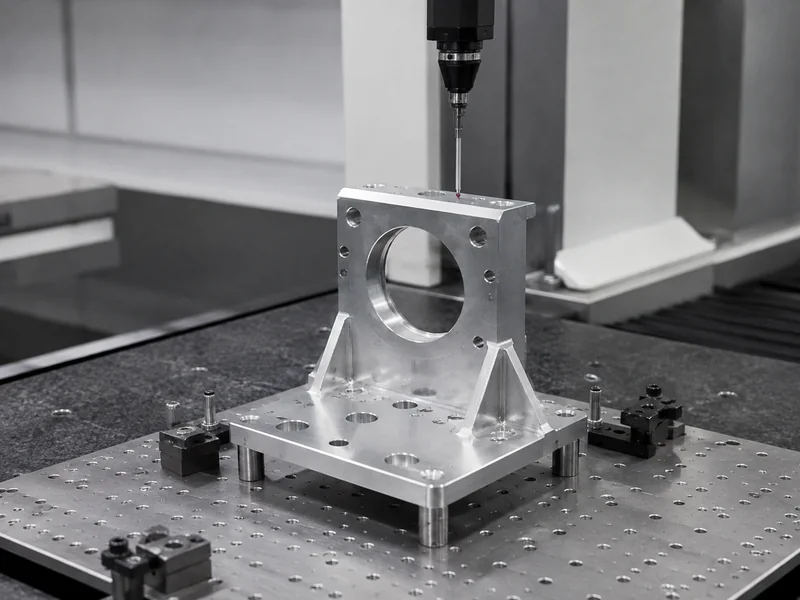
  • Check assembly-related true position before shipment.
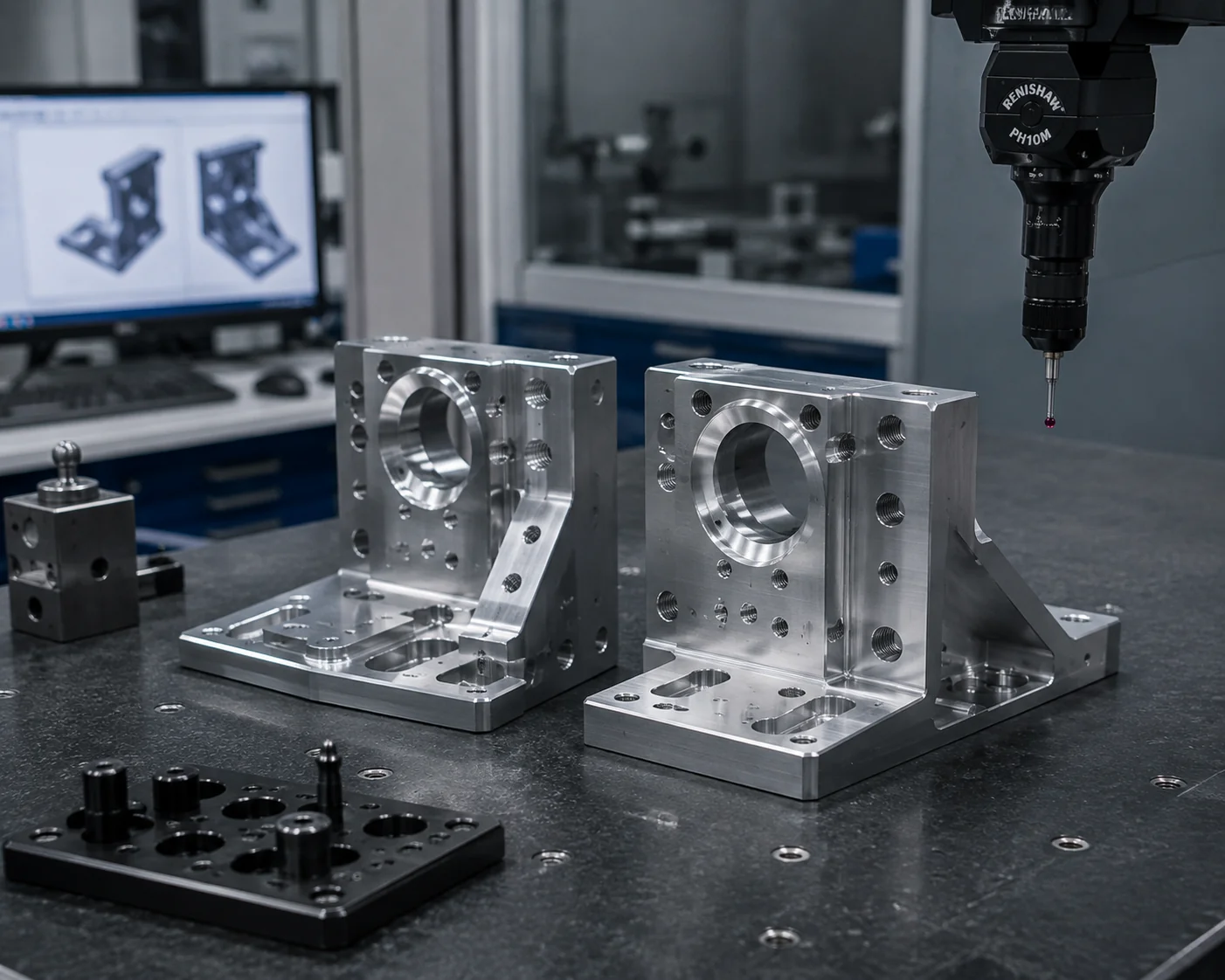
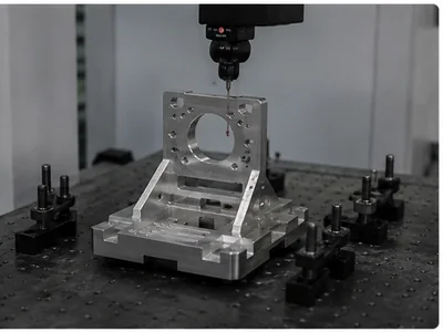
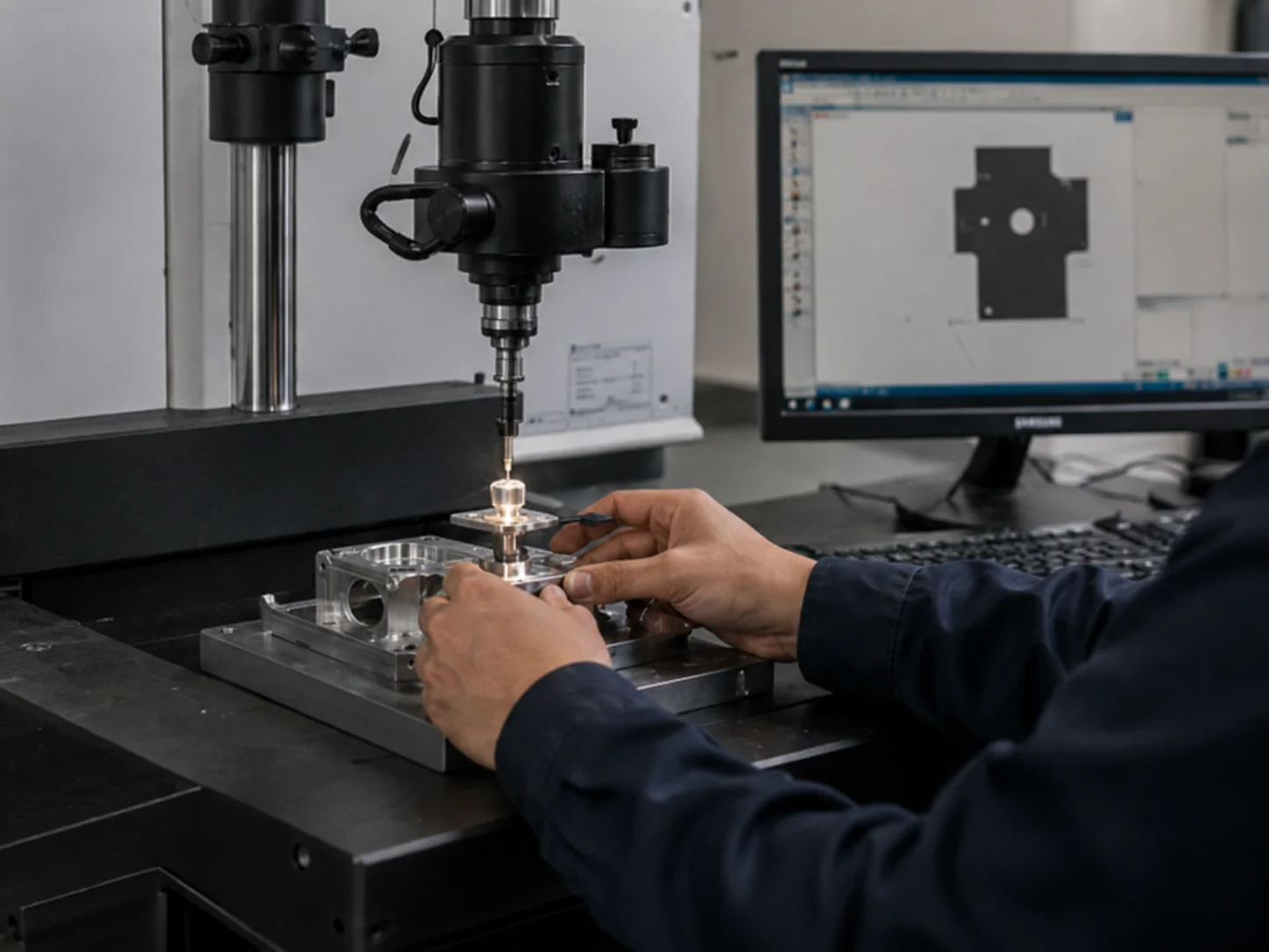
CMM Inspection of Bracket Hole Pattern
Core Challenge 02

Mounting Faces & Cross-Surface Features Lose Their Assembly Alignment

Each surface can measure perfectly flat on its own, but if the vertical face is not strictly perpendicular to the bottom mounting face, the motor tilts or the mating face leaves a gap.

Common Causes:

Excessive re-clamping, poor datum transfer, angular error during setup, or surface distortion from machining stress.

The LuckyHxs Approach

  • Define primary mounting surface and cross-face critical features.
  • Reduce unnecessary datum transfers via smart setup planning or multi-axis machining.
  • Inspect parallelism and perpendicularity according to drawing.
Multi-Surface Bracket Alignment
Core Challenge 03

Prototype Passes, but Mounting Geometry Drifts in Production

Prototype

  • Hole Pattern: PASS
  • Flatness: PASS
  • Thread: PASS

Production Batch

  • Hole Pattern: Shifts
  • Flatness: Changes
  • Thread: Gets Tight

Prototype Approval ≠ Automatic Mounting Repeatability. Tool wear, fixture condition, and thermal changes cause drift.

The LuckyHxs Approach

  • First Article verification for production setup.
  • In-process tool condition monitoring and thread review.
  • Final batch verification & repeat-order requirement retention.
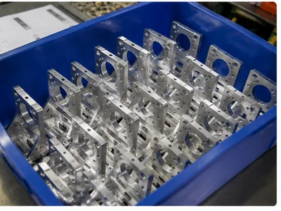
Repeat Production Batch of Machined Brackets

A Hole Pattern Only Works When It Is Located From the Correct Datum

Do not apply the same tolerance logic to every hole. We review drawings based on functional intent.

Primary Datum

Q: Where does the bracket physically seat?

Usually the main mounting face. This establishes the primary plane for all subsequent measurements.

Secondary Datum

Q: What controls lateral orientation?

Often a side surface, pilot, or locating edge that prevents rotation.

Locating Features

Q: What defines repeatable position?

Dowel holes, pilot bores, or precision bosses. These require strict true position tolerance.

Fastener Holes

Q: Are they clearance or locating?

Clearance holes allow the fasteners to pass through and should not be over-toleranced unnecessarily.

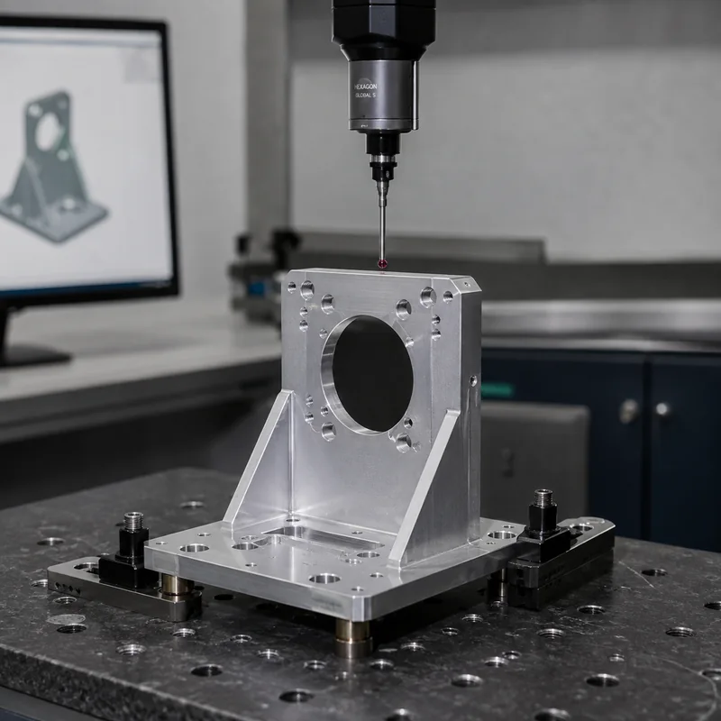
Bracket Flatness Inspection on Granite Table

A Correct Thickness Does Not Guarantee a Stable Mounting Plane

A mounting surface is a functional interface—not merely an exterior face.

  • Thickness vs. Flatness

    Thickness asks: Does the part meet overall size? Flatness asks: Does the actual mating surface seat correctly without rocking or bending the assembly?

  • Parallelism & Perpendicularity

    Are related surfaces correctly aligned? Does the vertical mounting interface maintain the intended 90-degree orientation for the sensor or motor?

  • Free-State Geometry

    Does the geometry change after unclamping? We inspect critical surfaces in their free state to ensure they don't warp out of tolerance.

Complex Brackets Need a Datum Strategy Before They Need More Axes

The real purchasing focus isn't "how many axes," but how critical features are related after machining.

  • Face A: Mounting Datum
  • Face B: Motor / Sensor Interface
  • Face C: Side Thread / Connector
  • Angled Face: Adjustment / Optical Interface

We evaluate 3-axis, indexed 4-axis, or full 5-axis machining to minimize datum transfers, improve tool access, and ensure cross-face inspection passes. 5-axis doesn't eliminate all errors—smart setup planning does.

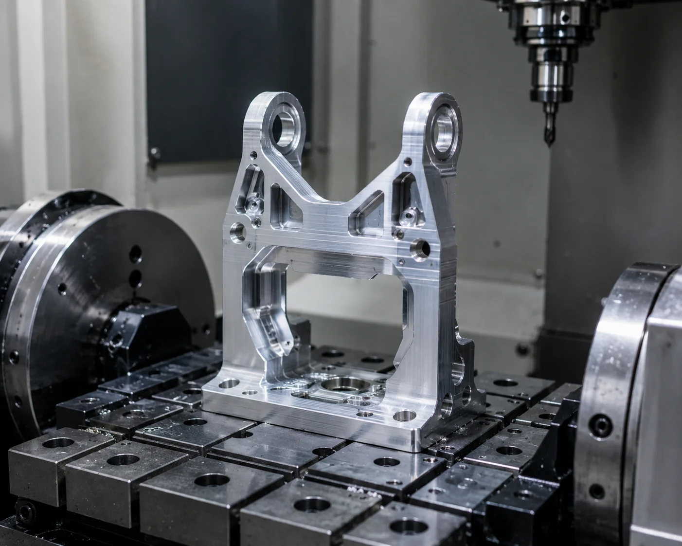
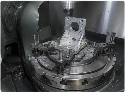
5-Axis CNC Machining of Complex Bracket

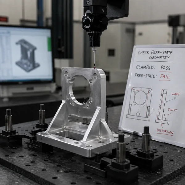
Clamped Geometry PASS Does Not Guarantee Free-State Geometry PASS

A bracket may measure correctly while constrained in the fixture and warp immediately after it is released due to residual stress.

High-Risk Geometries

  • • Large weight-reduction pockets
  • • Thin walls and thin bases
  • • Tall unsupported ears
  • • Open frame aluminum brackets (Robotics/Camera)

Our Control Strategy

  • • Plan roughing and finishing sequences
  • • Control workholding and clamping force
  • • Allow part relaxation where appropriate
  • • Inspect free-state mounting geometry
Lightweight Pocketed Aluminum Bracket

Threads, Slots & Finished Interfaces Must Work After the Bracket Is Complete

A. Threaded Holes

We check thread size, functional depth, entry condition, perpendicularity, and counterbore relationship.

Thread Gauge PASS ≠ Fastener Interface PASS

B. Adjustment Slots

We verify slot width, length, orientation, usable travel, and fastener clearance for proper assembly adjustment.

Slot Size PASS ≠ Adjustment Function PASS

C. Post-Finish Interfaces

Anodizing or plating changes dimensions. We account for finish buildup on dowel holes, pilots, and electrical contact surfaces.

Machining Complete ≠ Final Interface Complete

Inspect Brackets Around How They Mount and Align

Supplier Evaluation Mini Checklist:

  • Can the supplier identify functional datums?
  • Can they inspect hole position and flatness?
  • Can they control multi-face setups?
  • Can they retain approved production requirements?

Our 12-Step Quality Flow covers everything from Drawing Review and Functional Datum Identification to First Article Verification and Final Batch Verification. Inspection methods (CMM, Height Gauge, Thread Gauge) are selected based on drawing requirements.

CMM Inspection Height Gauge Inspection Thread Gauge Check Finished Bracket Batch

Where Custom CNC Machined Brackets Are Used

Industrial Equipment

Typical: Base mounting bracket

Concern: Hole position relative to primary datum.

Motors & Actuators

Typical: Motor mounting bracket

Concern: Pilot-to-bolt pattern and face flatness.

Sensors & Instruments

Typical: Sensor mount

Concern: Angular alignment and repeatable position.

Robotics

Typical: Robot interface bracket

Concern: Cross-face datum relationship.

Industrial Automation

Typical: Linear motion support

Concern: Parallelism across mounting points.

Optical / Camera

Typical: Machine vision bracket

Concern: Optical axis position and angle stability.

Electronics

Typical: Control module bracket

Concern: Connector alignment and heat contact.

Automotive & EV

Typical: EV control unit bracket

Concern: Batch repeatability and vibration stability.

Aerospace CNC machined bracket projects require project-specific drawing, material, inspection and certification review.

A CNC Manufacturing Partner You Can Verify

Certificates & Compliance Documents

ISO9001 CE REACH ROHS TEST REPORT
Factory Visit
Factory Visit
Production Review
Production Review
Technical Discussion
Quality Review
Quality Review

See CNC Machined Bracket Production at LuckyHxs

What Are CNC Machined Brackets? Types, Features & Applications

A CNC machined bracket is a precision mechanical component manufactured from solid material to mount, support, locate or align one component relative to another. Unlike a generic hardware bracket, a machined bracket may include precision mounting faces, dowel holes, threaded bosses, counterbores, pockets, slots and multi-surface features controlled from an engineering drawing.

What Does a Mechanical Bracket Do?

Beyond simple support, precision bracket components are designed to Mount, Locate, Align, Connect, and Maintain Position within complex assemblies.

Common Bracket Geometries vs Function

While brackets are often described by shape (L-Shaped, U-Shaped, Angle, Base, Bridge, Clevis), geometry alone does not define function. Two L-shaped brackets may require completely different tolerances because one is only a support while another locates a motor or optical sensor.

Feature → Function Mapping:

  • Dowel Hole: Repeatable Location
  • Pilot Bore: Centering
  • Bolt Pattern: Fastening
  • Mounting Face: Stable Contact
  • Slot: Adjustment
  • Pocket: Weight Reduction / Clearance
  • Threaded Boss: Direct Fastening

The best bracket classification starts with what the bracket mounts and which features control assembly—not simply whether it is L-shaped or U-shaped.
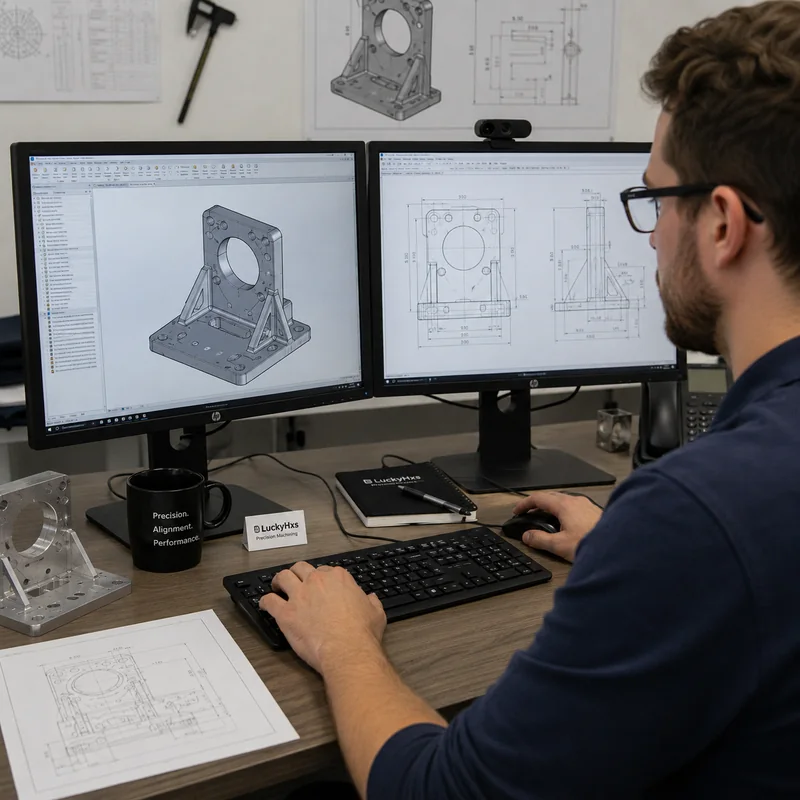
CNC Machined Brackets vs Sheet Metal Brackets: Which Should You Choose?

Both CNC machining and sheet metal fabrication can produce useful brackets, but they solve different engineering problems. The correct choice depends on wall thickness, geometry, required hole position, mounting-face accuracy, threads, volume and cost.

Requirement CNC Machined Sheet Metal
Precision locating hole ★★★★★ ★★★☆☆
Flat datum surface ★★★★★ ★★★☆☆
Thick threaded boss ★★★★★ ★★☆☆☆
Thin bent geometry ★★☆☆☆ ★★★★★
Complex pocket ★★★★★ ★☆☆☆☆
Simple high-volume support ★★☆☆☆ ★★★★★
Multi-side precision features ★★★★★ ★★☆☆☆

When CNC Machining is Appropriate

  • Motor mounting pilots
  • Sensor or optical/camera alignment
  • Dowel location
  • Multiple perpendicular faces
  • Complex pockets and thick bosses

When Sheet Metal May Be Better

  • Simple bent supports
  • Constant thin walls
  • No precision datum faces required
  • High-volume, low-complexity parts

Do not choose CNC because it sounds more precise. Choose CNC when the bracket function actually depends on machined mounting interfaces.

How Much Does CNC Machining a Custom Bracket Cost?

There is no fixed price for a custom machined bracket. Two brackets with the same outside dimensions can have very different machining costs if one requires only a profile and clearance holes while the other requires multiple setups, dowel holes, tight flatness, deep pockets and anodizing.

Main Cost Drivers

1. Material: Aluminum vs Stainless vs Titanium.
2. Raw Size: Large billet = more material cost.
3. Material Removal: Deep pockets take time.
4. Machined Faces: One face vs five faces.
5. Setups: More datum transfers = more setup time.
6. Tolerance: Tight true position/flatness costs more.
7. Features: Threads, dowels, counterbores.
8. Finishing & Inspection: Anodizing, CMM, FAI.

How Buyers Can Reduce Cost Without Hurting Function

  • Tighten only functional features (separate locating holes from clearance holes).
  • Use standard thread sizes and practical internal radii.
  • Avoid unnecessary deep pockets or cosmetic machining.
  • Identify final-finish dimensions clearly on the drawing.

The cheapest bracket is not the one with the loosest quote—it is the design that keeps precision only where the assembly needs it.

Frequently Asked Questions About CNC Machined Brackets

What is a CNC machined bracket?
A CNC machined bracket is a precision component milled or turned from solid metal or plastic. It is designed to mount, locate, and align other components (like motors or sensors) according to strict tolerances on a technical drawing.
What are the common types of mounting brackets?
Common precision types include equipment mounting brackets, motor & actuator brackets, sensor mounts, robotics interface brackets, camera/optical brackets, electronics module mounts, automotive/EV brackets, and custom multi-surface brackets.
When should I use a CNC machined bracket instead of sheet metal?
Use CNC machining when the assembly requires precision locating dowels, strict mounting face flatness, thick threaded bosses, complex pockets, or multiple perpendicular datum surfaces that sheet metal bending cannot hold.
Which materials are commonly used for machined brackets?
Aluminum (6061, 7075) is most common for lightweight and complex parts. Stainless steel (304, 316) is used for corrosion resistance. Free-machining steel, brass, and project-specific titanium are also used based on application requirements.
Can you machine aluminum brackets?
Yes. We regularly machine aluminum brackets, carefully controlling thin-wall distortion during roughing and finishing, and accounting for anodizing allowances on critical interfaces.
Can you machine brackets with threaded holes, dowel holes and slots?
Yes. We machine and inspect threaded holes (for depth and entry), dowel holes (for true position and fit), and adjustment slots (for functional travel range).
Can you machine complex multi-sided brackets?
Yes, subject to drawing review. The machining route may involve 3-axis, multi-side indexed, or 5-axis machining depending on the geometry and the required cross-face datum relationships.
How do you control bracket hole positions and mounting datums?
We identify the primary mounting datum, plan the machining sequence to minimize re-clamping, and inspect the true position of locating holes relative to those datums, rather than just checking hole diameters independently.
How much does a custom CNC machined bracket cost?
Cost depends on material, part size, material removal volume, number of setups, tolerance requirements, threads, surface finish, and quantity. A simple profile is cost-effective, while a 5-axis multi-datum bracket will cost more.
What information is needed for a bracket quote?
Please provide 2D/3D drawings (PDF, STEP), material, quantity, critical datums, flatness/perpendicularity requirements, surface finish, and inspection requirements.

Need a Bracket That Mounts the Assembly Where the Drawing Intended?

Send your 2D/3D drawing, material, quantity, mounting direction, critical datums, hole patterns, locating features, flatness, perpendicularity, threads, slots and finishing requirements. LuckyHxs will review the bracket geometry and machining route before quotation.

Talk to Engineering Team

Or email directly: admin1@lucky-hxs.com | +86 13342931453