Custom CNC Machined Valve Parts for Fluid-Control Assemblies
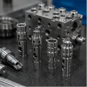
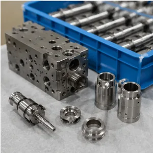
LuckyHxs manufactures precision CNC machined components used inside and around industrial valve assemblies. From valve bodies, spools and stems to seats, sleeves, needles, nozzles and threaded fittings, every part is produced to customer drawings for prototype and repeat production.
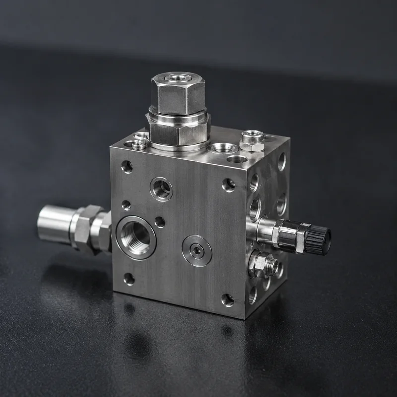
CNC Machined Valve Parts at a Glance
Feature-specific capability depends on material, geometry, mating fit, tolerance and inspection requirements.
Supply Type
Custom Made-to-Drawing Valve Components
Core Products
Bodies, Spools, Cores, Stems, Seats, Sleeves, Needles, Nozzles, Fittings
Machining Processes
CNC Turning, Milling, Swiss, Turn-Mill, Automatic Lathe, Drilling, Boring, Threading
Critical Features Controlled
Spool Fit, Bore, Seat, Thread, Port, Straightness, Burr, Surface
Materials Machined
Stainless Steel, Aluminum, Brass, Copper, Free-Machining Steel, Selected Plastics
Drawing Inputs Accepted
PDF, STEP, STP, IGES, DWG, DXF
Looking for finished industrial valves?
LuckyHxs manufactures the precision components used in valve assemblies. We do not position this page as a complete valve product catalogue or sell complete, pressure-rated valve units.
We Machine Valve Components—not Complete Valve Assemblies
A valve assembly may contain a body, spool or closure component, stem, guide, seat, sleeve, threaded interface and flow passages. LuckyHxs focuses on machining these individual components from customer drawings.
The valve OEM controls final assembly design, pressure rating, flow performance and validation. LuckyHxs controls the specified component geometry, sliding fits, and manufacturing requirements.
OEM Responsibility
Design, Pressure Class, Leakage Testing, Flow Cv, Final Certification.
LuckyHxs Responsibility
Machining to Drawing, Spool-to-Bore Tolerances, Thread Fits, Burr Control, Surface Finish.
CNC Machined Valve Components We Manufacture to Your Drawings
Precision components for sliding, sealing, guiding, and flow interfaces.
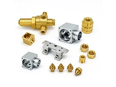
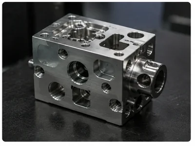
Valve Bodies & Housings
Small valve housings, cartridge bodies, threaded bodies, and multi-port fluid-control bodies.
Features: Main Bore, Pocket, Threads, Radial Port, Cross Hole.
Process: Turning, Milling, Turn-Mill.
Watch: Radial ports must correctly relate to the main flow path.
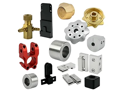
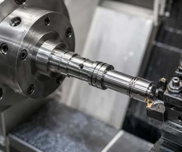
Valve Spools, Cores & Plungers
Control spools, sliding valve cores, cartridge cores, and precision plungers.
Features: Multiple ODs, Precision Lands, Grooves, Shoulders.
Process: Precision Turning, Swiss, Auto Lathe.
Watch: Multiple spool diameters must remain consistent with mating bore.
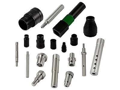
Valve Stems & Actuation Shafts
Valve stems, actuator shafts, guide stems, and small actuation pins.
Features: Precision OD, Guide Journal, Thread, Flat, Cross Hole.
Process: Turning, Swiss, Turn-Mill.
Watch: Stem must remain aligned through guiding and sealing interfaces.
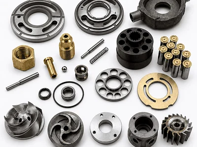
Valve Seats & Sealing Components
Seat rings, metal seat components, seal retainers, and backup rings.
Features: Sealing Diameter, Conical/Flat Seat, Retaining Feature.
Process: Precision Turning.
Watch: Sealing face dimensions pass, but actual mating contact fails.
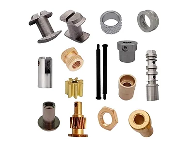
Valve Sleeves & Guide Bushings
Guide sleeves, stem bushings, spool sleeves, and ported cartridge sleeves.
Features: Thin Wall, Internal/External Groove, Radial Port.
Process: Turning, Cross-Drilling.
Watch: ID/OD pass individually, but thin-wall distortion ruins concentricity.
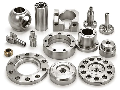
Poppets & Precision Needles
Valve poppets, metering needles, tapered components, and small control pins.
Features: Small Diameter, Taper, Conical End, Precision Stem.
Process: Swiss Machining.
Watch: Taper geometry and stem straightness relationship.
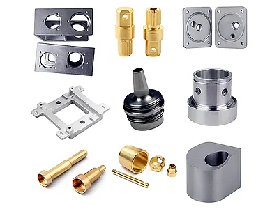
Nozzles, Orifices & Inserts
Precision nozzles, flow restrictors, jet components, and small fluid inserts.
Features: Small Bore, Cross Hole, Taper, Thread.
Process: Turning, Micro-Drilling.
Watch: Hole diameter passes, but burrs or chips remain inside.
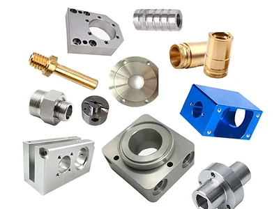
Threaded Fittings & Adapters
Connector bodies, port adapters, multi-port components, and custom threaded fittings.
Features: Internal/External Thread, Hex, Side Port, Off-Center Hole.
Process: Turning, Turn-Mill.
Watch: Thread gauge passes, but adapter fails to align with assembly.
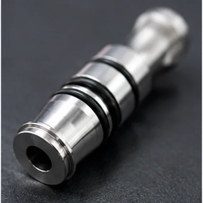
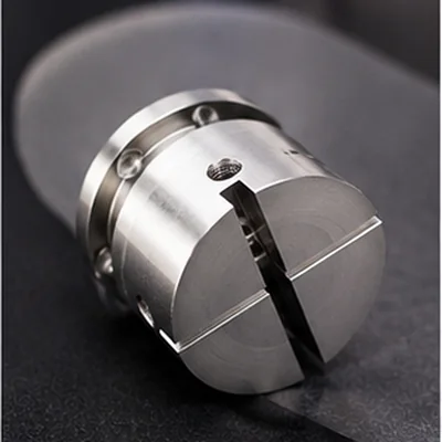
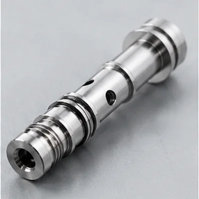
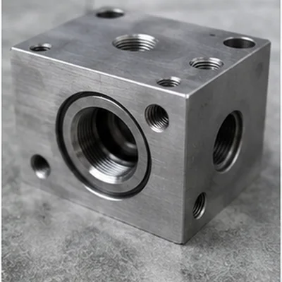
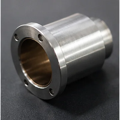
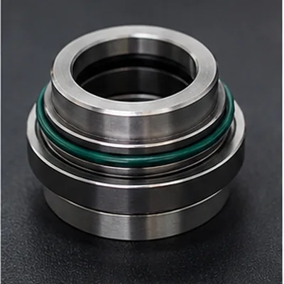
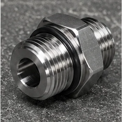
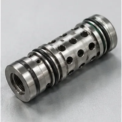
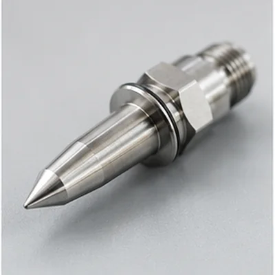
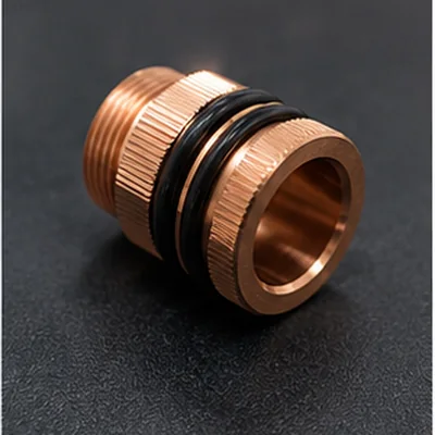
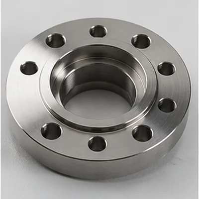
Precision Valve Parts for Sliding, Sealing, Guiding & Flow Interfaces
Every component plays a specific role in the final fluid-control assembly.
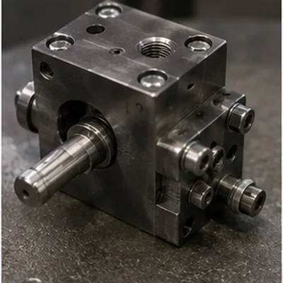
Materials for CNC Machined Valve Parts
Material selection should follow the customer drawing and actual operating environment. LuckyHxs machines the specified material; the customer defines final media compatibility.
STAINLESS STEEL
303 / 304 / 316 / 316L
Typical: Bodies, Stems, Sleeves, Fittings, Seats according to project.
ALUMINUM
6061 / 6063 / 6082 / 7075
Typical: Valve Housings, Pneumatic Bodies, Lightweight Fluid-Control Components.
BRASS
H57 / H59 / H62 / C3604
Typical: Fittings, Adapters, Valve Bodies, Nozzles, Threaded Components.
FREE-MACHINING STEEL
1214 / 1215
Typical: Selected stems, pins, plungers, threaded components.
COPPER / TITANIUM
Project Specific
Typical: Selected conductive or highly specialized corrosive environments.
ENGINEERING PLASTICS
POM / Nylon / PTFE / ABS
Typical: Seats, guides, lightweight bodies where applicable and confirmed.
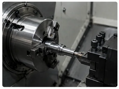
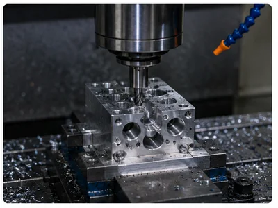
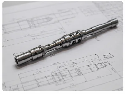
Choose the CNC Process From the Valve Component Geometry
The correct machining process depends on geometry, functional relationships, and quantity—not the name of the valve alone.
Why Valve Components Fail Even When Individual Dimensions Pass
Common risks when machining suppliers treat valve components as simple metal blocks rather than functional interfaces.
1. Spool & Bore Dimensions Pass, but the Valve Core Still Sticks
Affected: Spools, Cores, Bodies, Sleeves
Clearance is lost due to poor roundness, straightness, or surface finish, leading to erratic movement.
2. Sealing Surfaces Pass Dimensions but Fail at Assembly Level
Affected: Seats, Poppets, Needles, Bodies
The diameter is correct, but the mating angle, concentricity, or surface finish prevents proper contact.
3. Prototype Passes, but Critical Valve Fits Drift in Production
Affected: Repeat Batches, All Components
Tool wear and lack of in-process inspection cause spool fits, threads, and ports to shift over time.
4. Multiple Lands & Grooves Lose Relationship
Independent dimensions pass, but functional spacing fails.
5. Cross Holes Retain Burrs or Chips
Internal passages are obstructed, scratching sliding seals.
6. Threads Pass Gauging but Fail Assembly
Thread axis shifts relative to the main bore.
7. Stems Lose Straightness or Concentricity
Long shafts bend during machining, causing binding.
8. Tool Marks Damage Sliding Interfaces
Poor surface finish accelerates seal wear.
9. Material Grade Matches, Media Does Not
Wrong alloy variant causes corrosion in specific fluids.
10. Thin-Wall Bodies Distort After Machining
Clamping pressure causes ovality when released.
Spool & Bore Dimensions Pass but Functional Fit Fails
Why it happens: Clearance relationship, roundness, straightness, spool land geometry, surface condition, or burrs compromise the fit. Spool OD PASS + Bore ID PASS ≠ Functional Sliding Fit PASS.
The LuckyHxs Approach
- Review spool and mating-bore drawing together where available.
- Identify critical lands and mating clearance requirements.
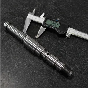
- Inspect roundness, straightness, and surface condition where specified.
- Protect functional sliding surfaces during handling.
What We Check (Per Drawing)
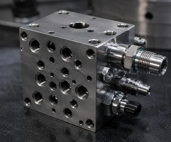
Sealing, Ports & Threads Pass Individually but Fail as One Interface
For bodies, seats, and multi-port components, individual dimensions often pass inspection, but the assembly fails because the seat-to-bore relationship is wrong, the radial port misses the internal passage, or the thread axis shifts.
The LuckyHxs Approach
- Identify the functional datum.
- Control thread-to-bore relationship.
- Review port position and cross-hole intersections.
- Deburr critical intersections and protect sealing faces.
Prototype Passes, but Critical Valve Fits Drift in Production
A perfect prototype approval does not guarantee repeat-batch stability. Tool wear, boring tool conditions, cutting heat, and deburring variations can cause spool fits, threads, and port positions to shift during mass production.
The LuckyHxs Approach
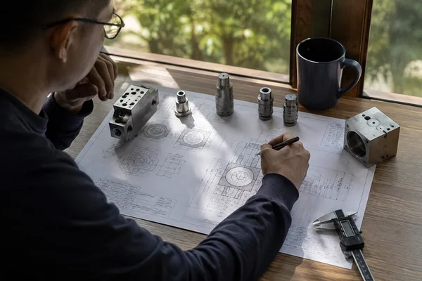
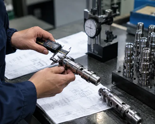
A Sliding Valve Fit Is a Relationship, Not Two Separate Diameters
Do not inspect mating valve components as unrelated parts.
1 Diameter
Does the feature meet its specified size?
2 Roundness
Does the sliding surface maintain the required circular geometry?
3 Straightness
Does a long spool or bore remain aligned across its entire length?
4 Surface
Will sliding contact be damaged by scratches or tool marks?
5 Burr & Cleanliness
Could an edge or remaining chip interfere with movement?
A Valve Seat Is a Functional Contact Surface—not Just a Diameter
A sealing diameter can pass dimensional inspection while the actual mating surface still fails to contact as intended due to poor geometry or surface damage.
Sealing Surface Checklist
- Correct geometry (seat angle where specified).
- Correct concentricity relationship to bore.
- Final finish inspected where applicable.
- No visible damage beyond drawing criteria.
- Protected during handling and packaging.
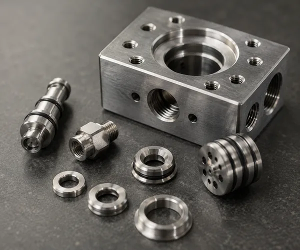
Hole Diameter PASS Does Not Mean the Internal Passage Is Acceptable
Uncontrolled burrs, metal chips, or sharp intersections in cross holes and radial ports can scratch sliding components or obstruct flow.
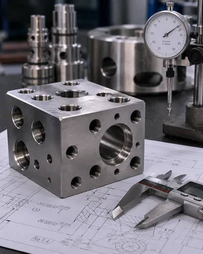
LuckyHxs Recommended Flow for Internal Passages
Machining & Intersection Review
Feature-Specific Deburring
Internal Cleaning (Per Project)
Visual / Magnified Review Where Appropriate
Slender Stems & Thin Valve Sleeves Create Different Machining Risks
A feature can measure correctly while clamped and change after the finished component is released.
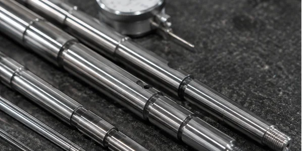
Stems & Needles
Deflection, Straightness loss, Runout, Taper relationship, Surface marks, Thread alignment.
Length-to-Diameter ratio, Support strategy, Swiss machining evaluation, Concentricity checks.
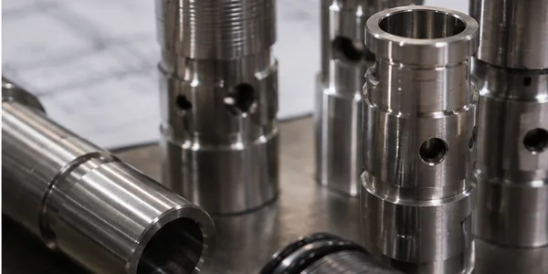
Thin-Wall Sleeves & Bodies
Clamping distortion, Bore ovality, Port movement, Wall thickness variation, Roundness change after release.
Machining sequence, Workholding strategy, Free-state inspection, Bore-to-Port relationship.
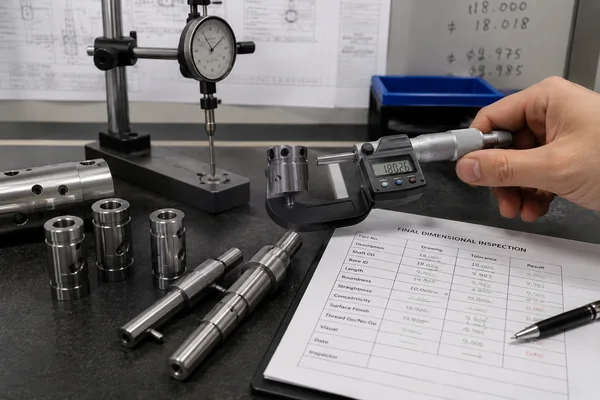
Critical Valve Fits Must Be Reviewed After the Final Manufacturing Step
Surface processing (like Nickel Plating, Zinc Plating, Black Oxide, Polishing, or Anodizing) can alter critical fit diameters, threads, grooves, and seat surfaces.
Does the critical tolerance apply Before Finishing or After Finishing? This must be defined on the drawing.
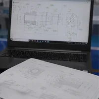
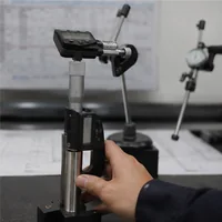
Inspect Valve Components Around Their Functional Interfaces
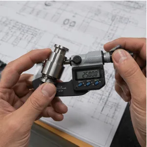
Inspection method is selected according to drawing, geometry and tolerance requirements.
12-Step Quality Flow
Where CNC Machined Valve Components Are Used
LuckyHxs supplies components for integration into various industrial fluid-control systems.
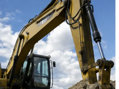
Hydraulic Equipment
Typical: Spools, Sleeves, Bodies
Concern: Spool Fit + Port Cleanliness
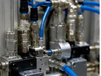
Pneumatic Systems
Typical: Bodies, Nozzles, Poppets
Concern: Thread + Port + Burr
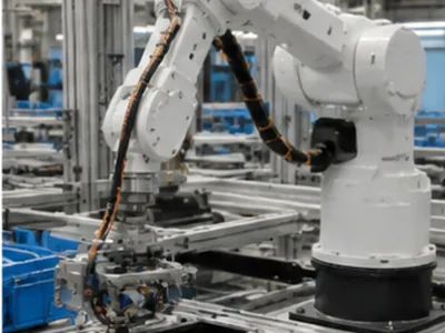
Industrial Automation
Typical: Control Spools, Stems
Concern: Repeatability + Sliding Geometry
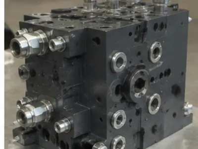
Fluid-Control Eq.
Typical: Seats, Needles, Adapters
Concern: Sealing Interface + Thread
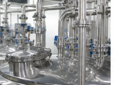
Process Equipment
Typical: Housings, Stems, Fittings
Concern: Material Grade + Surface

Energy & Power Eq.
Typical: Heavy Bodies, Guide Sleeves
Concern: Concentricity + Thread Fit
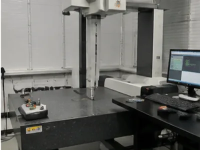
Precision Instruments
Typical: Micro Needles, Orifices
Concern: Small Bore + Burr Control
Industrial Machinery
Typical: Multi-Port Components
Concern: Port Position + Batch Stability
A CNC Manufacturing Partner You Can Verify
Reliable component supply backed by certified processes.
Certificates & Compliance Documents
What Buyers Can Verify
- Certified management and controlled production process
- Real factory visibility from production to inspection
- Quality records and material compliance available by project
What Are the Main Types of Industrial Valves—and Which Parts Require CNC Machining?
Industrial valves are mechanical assemblies used to start, stop, direct, regulate or prevent the reverse flow of liquids and gases. Different valve types use different internal mechanisms, which means their CNC-machined components also differ. LuckyHxs supplies these components according to customer drawings rather than complete valve assemblies.
BALL VALVE
Quarter-turn rotary valve.
Possible Machined Components: Valve Body, Stem, Seat Retainer, Threaded Adapter, Interface Components.
GATE VALVE
Linear motion valve.
Possible Machined Components: Stem, Seat Components, Body Interfaces, Threaded Components, Guide Components.
GLOBE / CONTROL
Linear motion for regulation.
Possible Machined Components: Stem, Seat, Plug / Poppet-Type Component, Body, Guide Sleeve.
DIRECTIONAL / SPOOL
Hydraulic/Pneumatic routing.
Possible Machined Components: Spool, Sleeve, Valve Body, Plunger, Adapter.
What Should Buyers Send?
How Are Precision Valve Components CNC Machined?
For LuckyHxs, valve manufacturing means machining the individual metal or engineering-plastic components that will later be integrated into a customer's valve assembly. The correct machining process depends on geometry and functional relationships.
VALVE BODY
Process: Turning, Milling, Boring, Cross Drilling, Turn-Mill.
Watch: Main Bore, Ports, Threads, Sealing Face.
SPOOL / CORE
Process: Precision Turning, Swiss, Automatic Lathe.
Watch: Land Diameter, Groove, Straightness, Surface.
STEM / NEEDLE
Process: Turning, Swiss, Turn-Mill.
Watch: Straightness, Thread, Taper, Surface.
SLEEVE / BUSHING
Process: Turning, Swiss, Cross Drilling.
Watch: ID / OD, Roundness, Port, Wall Thickness.
How Do You Choose a CNC Machined Valve Parts Manufacturer?
Choose a machining supplier around the functional requirements of the component—not generic claims such as "high precision."
Buyer Evaluation Checklist
- Do they manufacture components or complete valves?
- Can they understand mating spool/bore relationships?
- How do they control valve spool lands and grooves?
- How are sealing surfaces protected?
- How are cross holes and radial ports inspected?
- How are internal burrs and chips controlled?
- Can they support Swiss machining for small needles?
- How are thin-wall sleeves handled?
- How is repeat-batch dimensional drift controlled?
- What inspection documents can be supplied?
Supplier Warning Signs
Avoid suppliers who claim complete valve performance (like "zero leakage" or pressure ratings) without assembly testing. Be wary if they cannot explain how internal burrs are inspected, cannot identify mating features on your drawing, or quote before reviewing critical sliding fits.
Frequently Asked Questions About CNC Machined Valve Parts
What are CNC machined valve parts?
Does LuckyHxs manufacture complete valves?
What valve components can be CNC machined?
How are valve spools and mating bores controlled?
How do you control burrs in cross holes and internal passages?
Can you manufacture valve seats and sealing components?
Which materials can be used for valve components?
How much do custom CNC machined valve parts cost?
What information is needed for a quote?
Need Valve Components That Fit, Slide & Assemble as Designed?
Send your 2D/3D drawing, material, quantity, critical spool or bore dimensions, threads, ports, sealing surfaces, surface finish and inspection requirements. LuckyHxs will review the component geometry and machining route before quotation.