Custom Metric Aluminum Spacers Made to Your Drawings
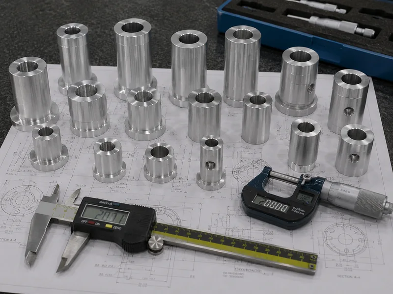
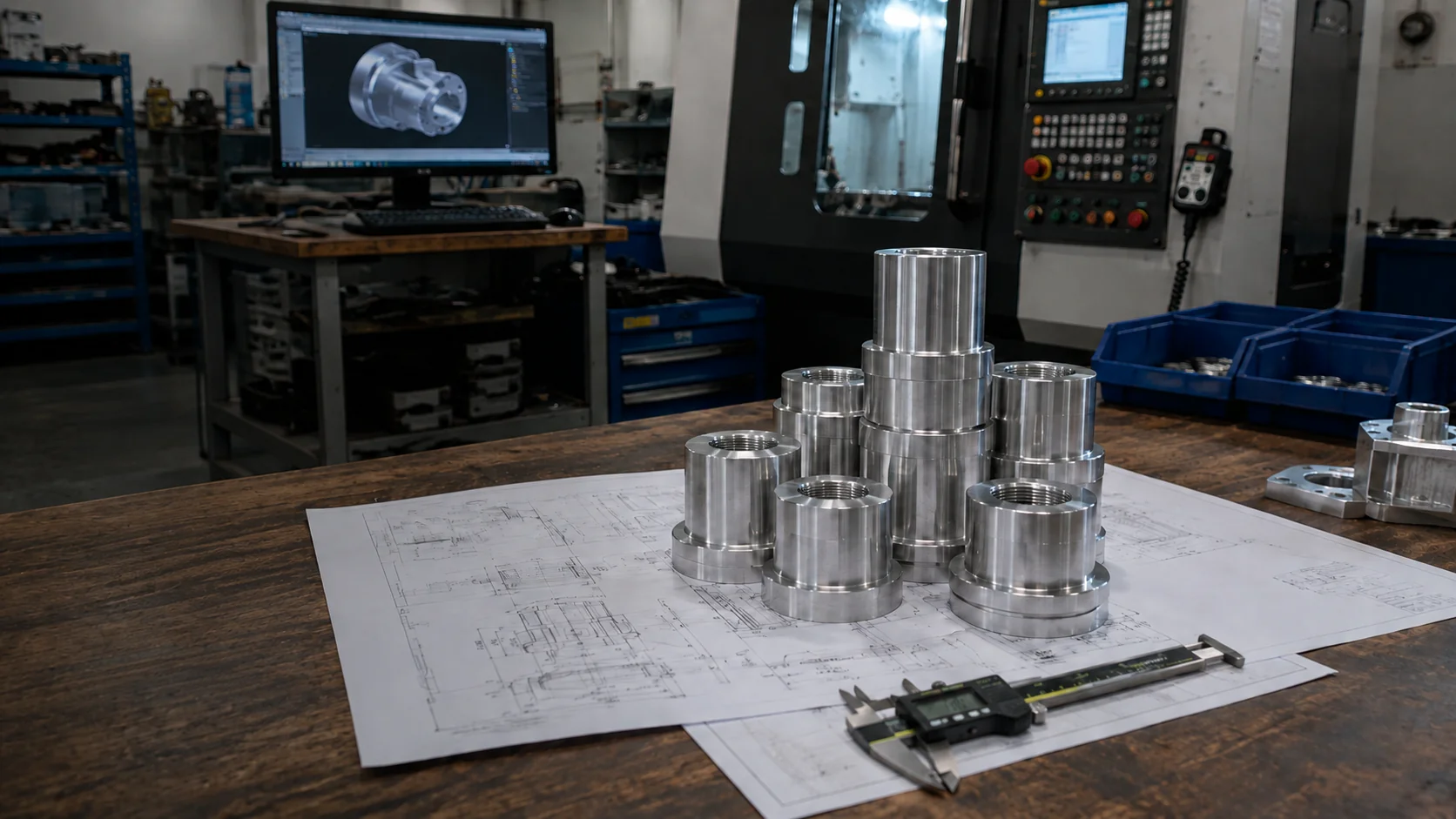
Precision unthreaded components designed to control assembly distance. We manufacture round, thin-wall, flanged, and stepped aluminum spacers with custom inside diameters, outside diameters, and overall lengths to match your exact metric clearance requirements.
- Custom ID, OD and Length configurations
- Metric Screw Clearance Options based on assembly needs
- Deburred, inspected, and ready for installation
- Support from prototyping to repeat batch production
Drawing-Based Custom Production
Manufactured strictly to your specifications.
Metric ID, OD & Length Review
Ensuring precise assembly clearance.
Deburring & Dimensional Inspection
Clean edges for flat seating.
Prototype to Repeat Production
Consistent quality across batches.
Metric Aluminum Spacers at a Glance
Key manufacturing parameters for your custom spacer projects.
Product Type
Unthreaded Spacers / Distance Sleeves
Main Material
Aluminum 6061, 6063, 7075
Alloy availability confirmed during quotation.
System of Measurement
Metric (Primary) / Imperial available
Screw Clearance
M2 to M12 reference range
Custom clearance holes based on drawing.
Custom Dimensions
Specified ID, OD, and Overall Length
Available Structures
Round, Flanged, Stepped, Thin/Thick Wall
Surface Finishes
As Machined, Clear/Black Anodized
Inspection Items
Length, Bore Size, End-Face, Burrs
Unthreaded Components That Control Assembly Distance
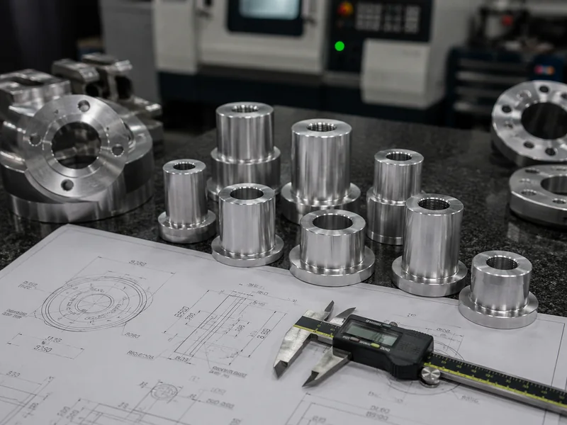
Metric aluminum spacers are usually cylindrical, unthreaded components designed to maintain a controlled distance between two mating parts. Unlike standoffs, which feature internal or external threads to fasten components together, a spacer allows a screw or bolt to pass entirely through its clearance hole.
In industrial assemblies, the overall length, hole diameter, outer diameter, and end-face condition of the spacer all directly affect the final alignment and structural integrity of the mounted components.
Important Note: Spacer performance depends on the complete assembly stack—not only the spacer’s nominal size. Threaded male-female or female-female products belong to the standoff category and are not the primary focus of this page.
Metric Aluminum Spacer Types We Manufacture
Customized to your exact geometric requirements and tolerance needs.
Round Unthreaded Metric Aluminum Spacers
Basic cylindrical spacers with a straight-through clearance hole. Can be customized based on metric screw size, ID, OD, and length.
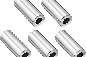
Precision-Length Aluminum Spacers
Manufactured with tight controls on overall length, end-face parallelism, and same-batch height consistency for multi-point mounting.
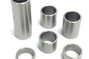
Thin-Wall Metric Aluminum Spacers
Designed for compact spaces and lightweight assemblies requiring a large through-hole relative to the outer diameter.
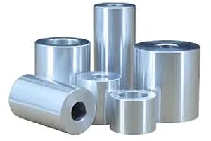
Thick-Wall Heavy-Duty Spacers
Features a larger end-face contact area and thicker wall for more stable compression support in industrial assemblies.
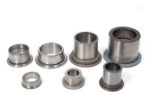
Flanged Metric Aluminum Spacers
Incorporates a flange to expand the contact surface, limit installation depth, or assist with component positioning. Single or double flanged available.
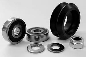
Stepped & Shoulder Aluminum Spacers
Combines positioning, spacing, and support functions. Ideal for locating into mounting holes, housings, or specific module cutouts.
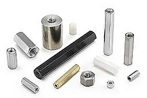
Long Aluminum Spacer Sleeves
Manufactured for longer assembly gaps. We focus on controlling straightness, internal bore cleanliness, and end-face parallelism over longer distances.

Custom Anodized Aluminum Spacers
Available in clear, black, or custom color anodizing. Critical dimensions are carefully reviewed to account for post-finish dimensional changes.
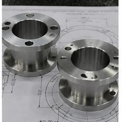
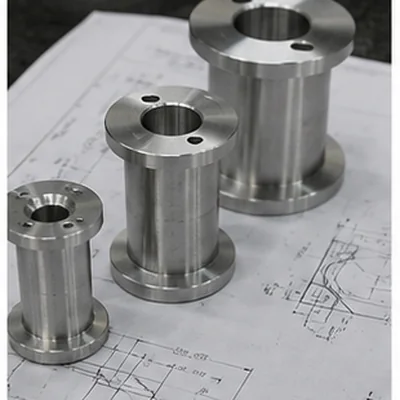
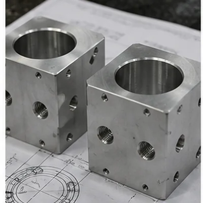
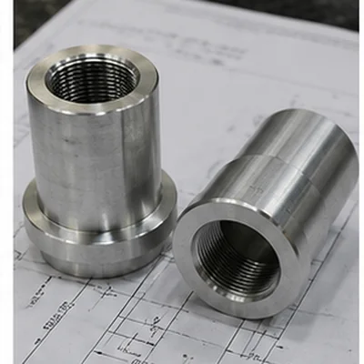
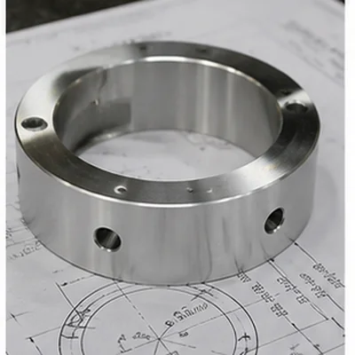
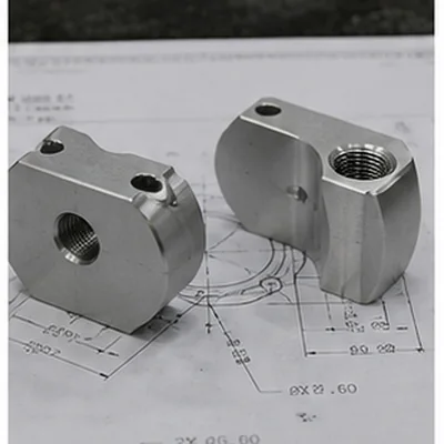
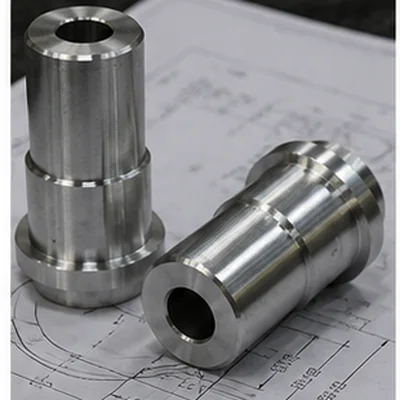
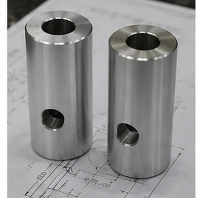
Custom Aluminum Spacer Structures
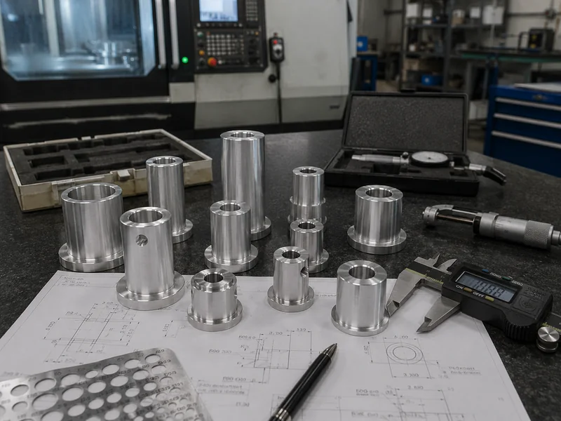
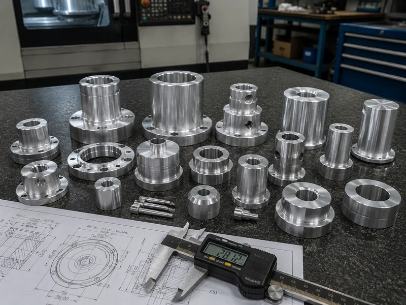
Examples of precision-machined geometries produced to customer drawings.
The Dimensions Buyers Should Define Before Quotation
Clear specifications ensure the machined spacer perfectly matches your assembly stack.
- Screw Size & Clearance Fit
- Inside Diameter (ID)
- Outside Diameter (OD)
- Overall Length (L)
- Wall Thickness
- Flange/Shoulder Diameters
- Step Lengths
- Material Grade (e.g., 6061)
- Surface Finish
- Critical Tolerances
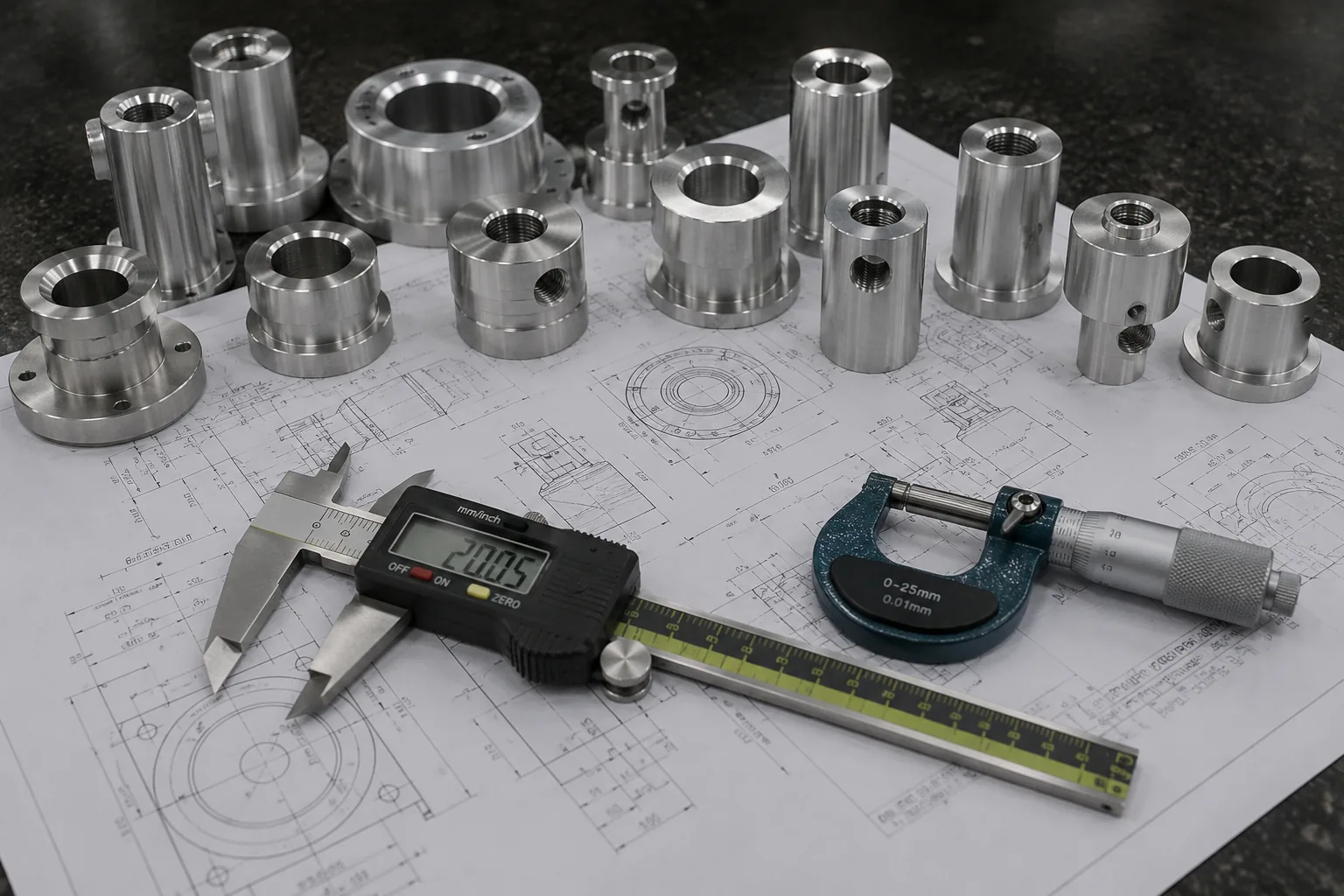
Why Metric Aluminum Spacers Cause Assembly Problems
Common manufacturing defects that disrupt industrial assembly lines.
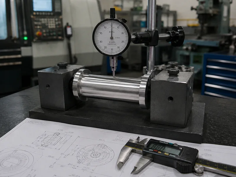
Keep Spacer Lengths from Tilting the Final Assembly
The Challenge
Spacers that are too long, too short or inconsistent can tilt mounting plates, raise PCBs, prevent covers from closing or change the intended assembly gap.
Why It Happens
- Overall length drifts during cutoff or facing.
- End faces are not machined parallel.
- Burrs add unintended height to the seating surface.
- Multiple spacers are produced under different process conditions.
- Finishing or handling damages the end faces.
How LuckyHxs Helps
- Review the functional stack height requirements.
- Identify overall length as a critical dimension.
- Machine and finish both end faces cleanly.
- Use first-article verification and in-process length checks.
- Inspect grouped spacers for batch consistency.
What We Check Before Shipment:
Match the Clearance Hole to the Metric Screw
The Challenge
A hole that is too small blocks screw insertion. A hole that is too large allows the spacer to shift, reducing alignment and assembly repeatability.
Why It Happens
- Screw size and clearance hole are confused during ordering.
- The drawing only lists a nominal M-size without specifying fit type.
- Drilling or boring dimensions drift over time.
- Burrs remain inside the hole, catching threads.
- Anodizing reduces the final bore diameter unexpectedly.
- The screw shank or coating thickness is not considered.
How LuckyHxs Helps
- Review the actual screw and required clearance fit.
- Confirm whether the dimension is pre-finish or post-finish.
- Machine controlled internal diameters.
- Add appropriate entry chamfers.
- Remove internal burrs and chips.
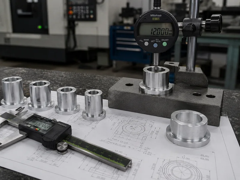
- Inspect key bores using suitable measuring tools (e.g., pin gauges).
What We Check Before Shipment:
Maintain Stable Dimensions from Samples to Repeat Batches
The Challenge
Approved samples may assemble correctly, while later batches show unexpected changes in length, bore size, outer diameter, wall thickness or anodized appearance.
Why It Happens
- Tool wear is not monitored during long runs.
- Length offsets are not adjusted correctly on the lathe.
- Different material lots behave differently during machining.
- Manual deburring methods change critical dimensions.
- Anodizing changes fit due to inconsistent film thickness.
- Inspection requirements are not retained for repeat orders.
How LuckyHxs Helps
- Confirm critical dimensions during drawing review.
- Use strict first-article verification.
- Apply regular in-process checks and monitor tool wear.
- Review dimensions before and after surface finishing.
- Retain approved drawings and inspection requirements for repeat orders.
More Spacer Problems to Address Before Production
We review these factors during quotation to prevent assembly failures.
Nonparallel End Faces
Consequence: Mounted components tilt; uneven stress distribution.
Review: Facing operations and cutoff methods.
ID and OD Eccentricity
Consequence: Uneven wall thickness; potential interference with nearby parts.
Review: Machining setup and concentricity tolerances.
Thin-Wall Collapse
Consequence: Spacer deforms under clamping load.
Review: Wall thickness relative to material strength.
Burrs and Sharp Edges
Consequence: Prevents full seating; scratches mating surfaces.
Review: Deburring processes and chamfer specs.
Anodizing Dimensional Change
Consequence: Clearance hole becomes too tight for the screw.
Review: Pre-finish vs. post-finish dimensions.
Appearance Variation
Consequence: Visible parts look mismatched on the final product.
Review: Alloy consistency and finishing controls.
Dissimilar-Metal Corrosion Risk
Consequence: Galvanic corrosion when aluminum contacts steel in harsh environments.
Review: Environmental conditions, material selection, and protective coatings.
Choosing Aluminum for Metric Spacers
Final alloy availability is confirmed during quotation based on your drawing and volume.
Aluminum 6061
The most common general-purpose alloy. Offers a good balance of strength, machinability, and corrosion resistance.
- Excellent for standard spacers
- Good anodizing response
- Cost-effective for medium strength
Aluminum 6063
Often used for components where surface finish and anodizing quality are paramount. Slightly lower strength than 6061.
- Superior cosmetic anodizing
- Excellent surface finish
- Good for visible architectural/electronic parts
Aluminum 7075
A high-strength alloy used when the spacer will be subjected to higher compressive loads. More expensive and harder to anodize for cosmetics.
- High mechanical strength
- Better for heavy-duty clamping
- Harder to achieve perfect cosmetic anodizing
Custom Spacer Geometry Built Around Your Assembly
We machine structural features to aid positioning and installation.
Surface Finishes for Aluminum Spacers
Protecting the material and improving cosmetic appearance.
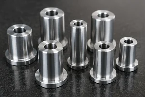
As Machined
Standard turned finish. Cost-effective for internal parts.
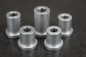
Clear Anodized
Corrosion resistance while maintaining a silver appearance.
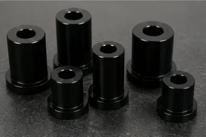
Black Anodized
Popular for optical equipment and sleek electronics.
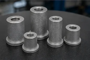
Sandblasted & Anodized
Matte finish that hides light machining marks.
Important Finishing Considerations:
- Anodizing can affect inside and outside dimensions. Critical fits should be defined as final post-finish dimensions on your drawing.
- Color consistency depends on alloy, pretreatment, and finishing controls.
- Cosmetic requirements should be identified separately from functional dimensions.
- Contact points or rack marks should be discussed for highly visible components.
The most suitable process is selected after reviewing part diameter, length, wall thickness, quantity and tolerance requirements.
Machining Capabilities for Custom Aluminum Spacers
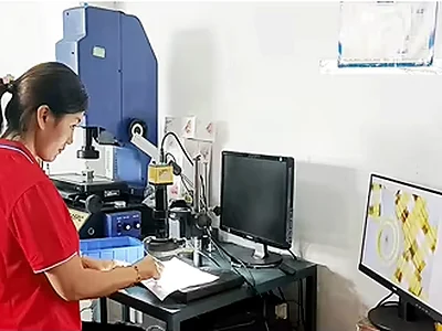
What We Inspect Before Aluminum Spacers Ship
Our quality control process focuses on dimensional stability and assembly readiness.
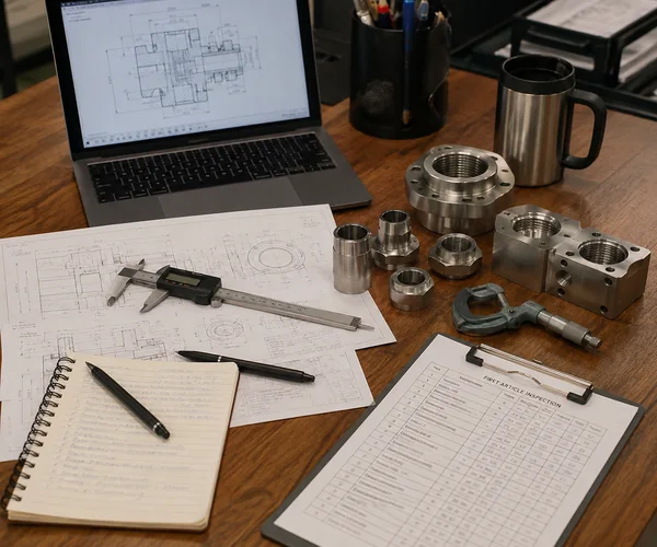
Drawing Review
Checking revisions, material, and critical tolerances.
First-Article Check
Verifying the initial setup against the drawing.
In-Process Checks
Monitoring length, ID, and OD during the run.
Final Verification
Post-finish dimension review and batch inspection.
Key Inspection Items:
- ✓ Overall Length
- ✓ Inside Diameter
- ✓ Outside Diameter
- ✓ Wall Thickness
- ✓ Concentricity (If spec'd)
- ✓ End-Face Condition
- ✓ Chamfer
- ✓ Burrs & Cleanliness
- ✓ Anodized Appearance
- ✓ Packaging Protection
Where Metric Aluminum Spacers Are Used
Industrial and electronic assemblies requiring precise distance control.
PCB & Electronics
Maintain a defined gap between circuit boards and chassis, protecting components and solder joints.
Sensor Components
Support stacked components and align sensors at exact heights relative to targets.
Camera & Optics
Improve alignment and create precise focal distances within optical equipment housings.
Motor Mounts
Provide screw clearance and rigid support when mounting motors to frames.
Robotics & Automation
Create space for wiring or moving features between structural plates.
Instrument Panels
Offset display screens or control boards behind the main user interface panel.
Industrial Enclosures
Keep internal mounting plates separated from the outer shell.
Equipment Frames
Protect components from direct contact and align heavy-duty structural members.
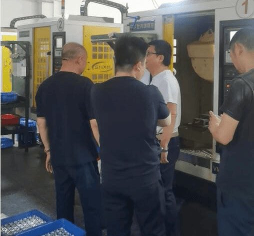
A Spacer Manufacturing Partner You Can Verify
Certified quality systems and real production facilities.
 ISO9001
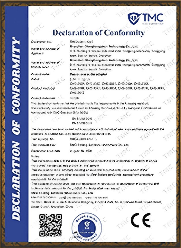 CE
CE
 REACH
REACH
 ROHS
ROHS
 TEST Reports

What Are Metric Aluminum Spacers Used For?
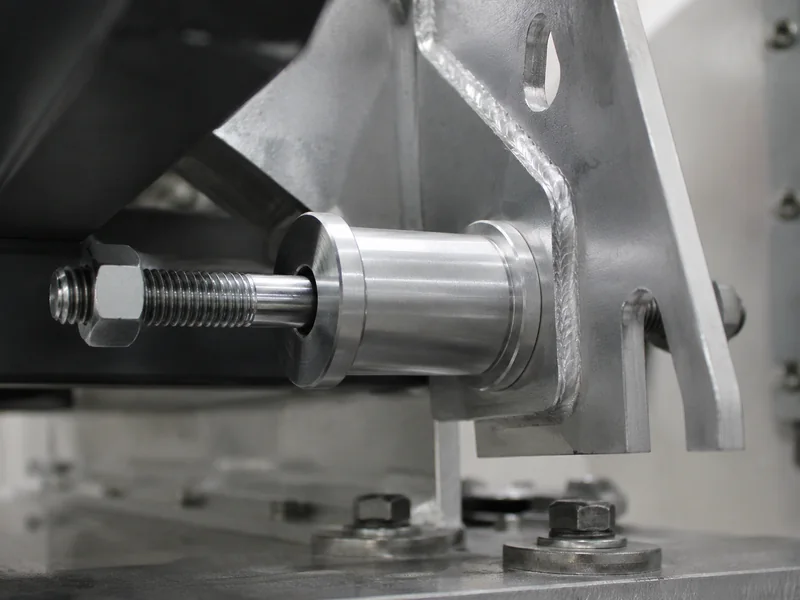
At their core, metric aluminum spacers are unthreaded cylindrical components designed to maintain a defined gap between assembled components. They allow a metric screw or bolt to pass entirely through a central clearance hole, clamping the assembly together while the spacer bears the compressive load.
In industrial applications, they are used to support PCBs, elevate panels, separate covers, position sensor modules, align motor mounts, and build automation assemblies. They help engineers control assembly height, ensure parallel alignment, and provide necessary clearance for moving parts or airflow.
It is important to note that spacers are normally unthreaded and should not be confused with threaded standoffs. The correct spacer must match the metric screw size (e.g., M3, M4, M5), the required gap (overall length), and the available installation space (outside diameter). Common selection mistakes involve specifying a nominal screw size without defining the actual required clearance hole diameter, or failing to account for length tolerances across multiple support points.
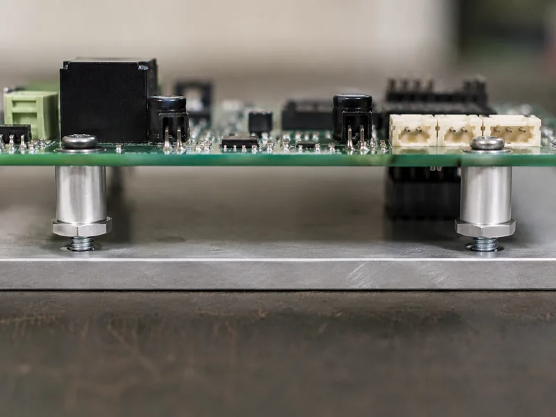
Why Are Aluminum Spacers Used Under PCBs and Mounting Plates?
Spacers keep circuit boards and mounting plates elevated away from the base surface or chassis. This clearance is critical to protect sensitive electronic components, solder joints, and wiring from short circuits, while also providing necessary ventilation paths for heat dissipation.
When mounting a rigid board, equal spacer lengths are essential. Consistent lengths help prevent PCB bending or mounting-plate tilt when the screws are tightened. Furthermore, burrs, uneven end faces, or mixed lengths within a batch can create concentrated stress points that may crack a board during assembly or vibration.
While aluminum offers a lightweight, strong, and easily machinable metal option, engineers must remember that aluminum is electrically conductive. Electrical contact, grounding paths, and galvanic corrosion requirements must be reviewed. If absolute electrical isolation is required, insulating materials (like nylon) may be necessary, or specific non-conductive coatings must be applied and verified. The customer must define the screw size, clearance, stack height, and whether electrical isolation is required during the design phase.
How Do You Choose the Right Metric Spacer Size?
Choosing the correct metric spacer requires confirming several interconnected dimensions simultaneously. You must define the metric screw size and its corresponding clearance-hole diameter, the spacer outside diameter, overall length, and wall thickness. Additionally, you should consider available installation space, required compression support, surface finish, and environmental conditions.
If the hole is too small, the screw may not pass through. If the hole is too large, the spacer may shift around the screw off-center. If the spacer is too long or too short, the final assembly height will be incorrect. If the wall is too thin, the spacer may deform under clamping load. Finally, if anodizing is required, critical internal and external fits should be reviewed as final post-finish dimensions.