

Precision CNC turned parts are custom rotational components whose diameters, lengths, shoulders, bores, threads, grooves, and related features must meet the drawing and work together in the final assembly. The word “precision” does not define one universal tolerance; the functional features, material, geometry, process route, finishing, and inspection method determine what must be controlled.
LuckyHXS supplies made-to-drawing or sample-based metal and engineering-plastic turned components, including shafts, sleeves, bushings, pins, spacers, connectors, threaded inserts, fasteners, and other non-standard parts. For a commercial capability overview, visit the CNC turned parts manufacturer, CNC turning service, and CNC turning parts pages. The answers below focus on the technical and acceptance questions to close before quotation and production.
1. What Are Precision CNC Turned Parts?
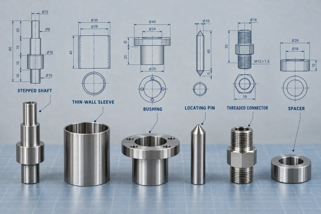
Precision CNC turned parts are components produced by rotating bar stock or a blank while controlled cutting tools form cylindrical and related features to drawing requirements. Common operations include facing, outside turning, boring, drilling, threading, grooving, cutoff, and chamfering.
The process is well suited to parts whose main geometry is organized around an axis. Examples include shafts, pins, bushings, sleeves, spacers, collars, fittings, connectors, threaded inserts, valve components, and round housings. A turned part may also receive milling, grinding, heat treatment, plating, polishing, deburring, or cleaning before final acceptance.
Precision should be defined by the characteristics that make the part function. These may include a bearing diameter, bore fit, shoulder location, face-to-face length, thread fit, total runout, surface texture, or relationship between features. Learn more about the basic process in What Is CNC Turning?.
2. Where Are Precision CNC Turned Parts Used, and Which Shapes Are Best Suited?
CNC turning is usually the right starting process when the component is mainly round or cylindrical and most features share a central axis. Shafts, pins, sleeves, bushings, spacers, collars, nozzles, fittings, and threaded bodies are typical candidates.
These parts are used in industrial equipment, automation, automotive assemblies, electronics, fluid-control systems, instruments, and other products that need repeatable round features, fits, threads, or sealing surfaces. The application name alone does not prove that a part meets industry-specific requirements; buyers should separately define the material, inspection, documentation, cleanliness, traceability, and regulatory requirements that apply to their project.
Look at the geometry rather than the part name. Turning is a strong fit when the drawing is dominated by:
- Outside and inside diameters
- Faces and axial shoulders
- Bores and counterbores along the main axis
- Internal or external threads
- Circumferential grooves and undercuts
- Tapers, radii, and chamfers
- Repeated round features that benefit from one rotational setup
Milling is usually more appropriate when the part is dominated by flat faces, pockets, slots, irregular profiles, or hole patterns on several planes. Turning is attractive when one setup can establish several related diameters, bores, faces, and threads around the same axis; this can simplify control of their functional relationships. If the part combines both families, compare the functional features in our CNC turning vs CNC milling guide.
3. What Types of Precision Turned Components Can Be Made?
Precision turning can produce many custom part families, provided the requested size, material, geometry, tolerance, and inspection requirements fit the selected supplier’s equipment and process.
Common examples include:
- Shafts: stepped, motor, drive, actuator, and locating shafts with controlled bearing or seal diameters
- Pins: locating, guide, contact, hinge, dowel-style, and threaded pins
- Sleeves and bushings: parts with related inside and outside diameters, wall thickness, end faces, and fit requirements
- Spacers and collars: components whose length or shoulder position controls an assembly stack
- Threaded parts: inserts, studs, nuts, connectors, fittings, and custom fasteners
- Round bodies: nozzles, adapters, valve bodies, sensor bodies, and cylindrical housings
- Turn-mill parts: rotational components with flats, cross holes, slots, side threads, or other off-axis features
For deeper examples, review machined shafts, custom sleeves, custom bushings, CNC machined pins, and custom threaded inserts.
4. Should My Part Use Standard CNC Turning, Swiss Machining, or Turn-Mill Machining?
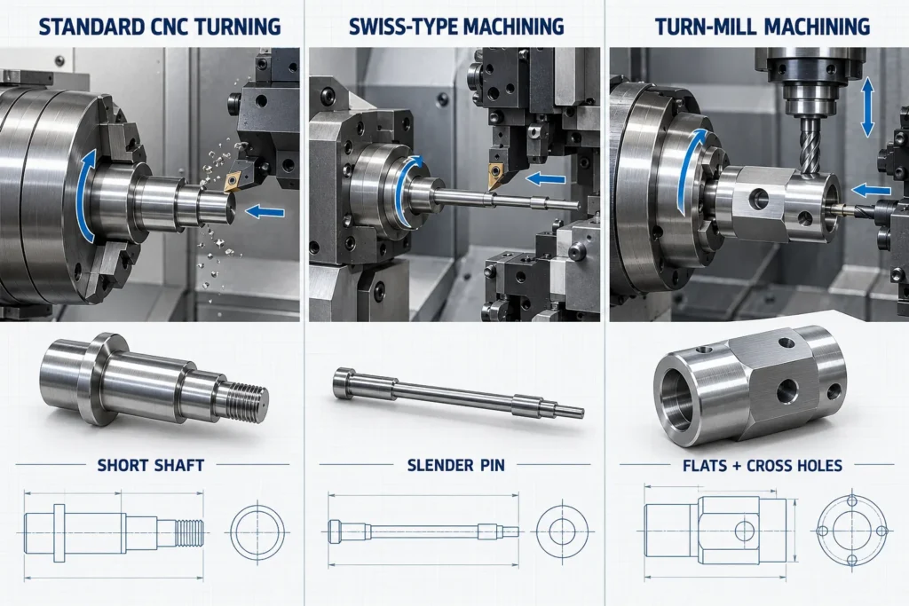
The best process depends on the part’s diameter, length-to-diameter ratio, feature access, setup relationships, quantity, and tolerance—not on which machine sounds most advanced. Standard CNC turning is suitable for many general shafts, sleeves, bushings, spacers, fittings, and threaded components.
Swiss-type machining can be useful for small or slender parts because the workpiece is supported near the cutting zone. It is often considered for connector pins, micro shafts, long narrow components, and feature-dense parts made from bar stock. The actual fit still depends on the supplier’s machine range, tooling, geometry, and order requirements.
Turn-mill machining becomes relevant when a rotational component also needs flats, cross holes, keyways, slots, radial threads, or other off-axis features. Combining operations may reduce transfers and protect relationships between features, but a separate turning and milling route may still be more practical for some parts.
Ask the supplier to state the proposed process, number of setups, datum strategy, and inspection plan. Review CNC turning and milling services when the drawing contains both rotational and milled geometry.
5. What Minimum and Maximum Part Sizes Can Be Turned?
There is no universal minimum or maximum size for precision CNC turned parts because capacity depends on the specific machine, chuck or collet, bar feeder, spindle bore, support method, tooling, and part geometry. Diameter alone is not enough to confirm manufacturability.
A small part may be difficult because of fragile features, tool access, burr control, or inspection limitations. A large part may exceed available swing, bar, chuck, torque, or workholding capacity. A long part may require tailstock, steady support, guide-bushing support, or a different operation sequence.
Provide these dimensions with the RFQ:
- Maximum raw-stock and finished diameter
- Overall length
- Longest unsupported length
- Smallest bore, groove, thread, or wall feature
- Length-to-diameter ratio
- Required stock form
- Features near the cutoff end or chucking area
Ask for part-specific confirmation rather than relying on a general size chart. The same nominal diameter can require a different route when wall thickness, material, tolerance, or off-axis features change.
6. Which Materials Are Commonly Used for Precision CNC Turned Parts?
Precision turned parts are commonly made from aluminum, stainless steel, carbon or alloy steel, free-machining steel, brass, copper, and engineering plastics, but the exact grade and condition must match the part’s function and manufacturing route. “Aluminum,” “stainless,” or “plastic” is not a complete material specification.
Material choice affects machinability, tool wear, heat generation, chip control, distortion, thread quality, surface finish, corrosion behavior, conductivity, weight, and post-processing. Engineering plastics introduce additional concerns such as thermal expansion, moisture response, clamping deformation, and burr formation.
Include the following information:
- Exact grade, alloy, temper, hardness, or condition
- Applicable material standard
- Bar, tube, billet, or customer-supplied blank requirement
- Whether an alternative may be proposed
- Required material documentation
- Service temperature, corrosion, wear, conductivity, or insulation needs
- Planned coating, plating, heat treatment, or cleaning process
LuckyHXS’s confirmed scope includes custom metal and engineering-plastic machined parts. Grade availability, traceability documents, and permitted alternatives should be confirmed for the specific project.
7. What Tolerances Can Precision CNC Turning Achieve?
No single tolerance applies to every precision CNC turned feature. Achievable tolerance depends on the material, diameter, length, wall thickness, feature type, tool access, number of setups, thermal behavior, finishing sequence, production quantity, and measurement method.
Define tolerances according to function instead of applying the tightest value to every dimension. A bearing seat, sealing diameter, press fit, locating shoulder, thread, or mating bore may need close control, while non-functional clearance features can often use a wider general tolerance.
For every critical characteristic, ask:
- What function does the tolerance protect?
- Which datum or axis controls it?
- Can the feature be cut and measured in one setup?
- Does the tolerance apply before or after finishing?
- What measurement method and fixture will be used?
- Will the feature require grinding, honing, reaming, or another secondary process?
- What inspection frequency and record are required?
Machine resolution and measuring-instrument resolution are not finished-part guarantees. The supplier should confirm capability against the actual feature and inspection plan. See how tight tolerances affect CNC machining cost before tightening every dimension.
8. What Is the Difference Between Roundness, Concentricity, Coaxiality, and Runout?
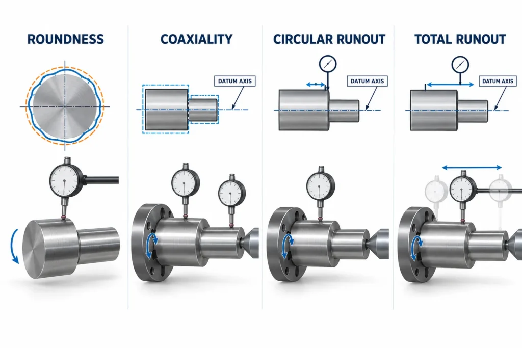
These controls describe different aspects of rotational geometry and should not be used interchangeably. Roundness controls the shape of a circular element without requiring a datum. Coaxial relationships concern how axes align. Runout evaluates surface variation as the part rotates relative to a datum axis.
In practical sourcing terms:
- Roundness asks whether one circular cross-section is sufficiently round.
- Cylindricity controls the complete cylindrical surface without a datum.
- Coaxiality or axis alignment concerns whether related cylindrical features share the required axis.
- Circular runout checks variation at individual circular sections during rotation.
- Total runout checks variation across the full controlled surface during rotation.
Do not write “perfectly centered” or “extremely low runout” as an informal note. Define a measurable requirement, datum, tolerance zone, and acceptance method. For shafts, bushings, bearing seats, and sealing diameters, show which feature establishes the datum axis and which feature rotates or locates relative to it.
Ask the manufacturer how the part will be held during measurement. Chucking force, fixture condition, indicator position, part support, temperature, and surface finish can affect the result.
9. Why Are Long Slender and Thin-Wall Turned Parts More Difficult?
Long slender and thin-wall parts are more difficult because cutting force, clamping pressure, heat, vibration, and residual stress can move the workpiece during machining or after release. A dimension that passes while clamped may change when the part is removed from the machine.
Typical risks include:
- Deflection and taper on long shafts
- Chatter and inconsistent surface texture
- Out-of-round bores or outside diameters
- Uneven wall thickness
- Distortion after cutoff or unclamping
- Collapse from excessive chuck or collet pressure
- Plastic movement caused by heat or moisture
- Inspection error caused by unsupported measurement
Provide the overall length, diameter, wall thickness, material condition, free-state requirement, and functional fits. Ask how the part will be supported, which operations occur before cutoff, whether roughing and finishing are separated, and when the final measurement is taken.
There is no universal minimum wall thickness or maximum length-to-diameter ratio. The supplier should evaluate the specific drawing, stock condition, tooling, support method, tolerance, and quantity.
10. How Should Threads, Grooves, Chamfers, and Burrs Be Specified?
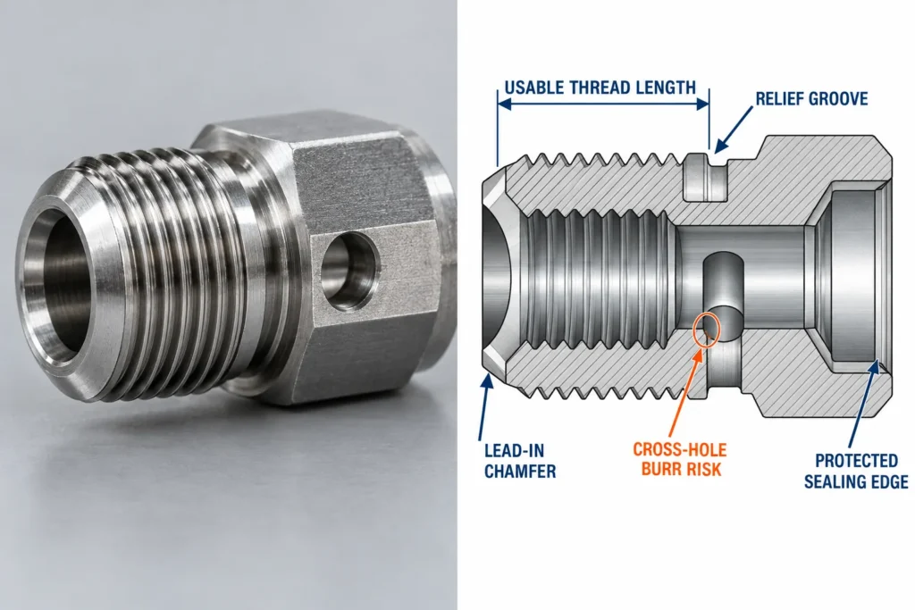
Threads, grooves, chamfers, and edge conditions should be defined with measurable drawing requirements because nominal size alone does not determine assembly performance. A thread can pass one check yet still fail because the usable length, entry chamfer, relief, coating buildup, or mating alignment is wrong.
For threads, provide:
- Standard, size, pitch, and class or fit
- Internal or external designation
- Usable thread length
- Lead-in chamfer and thread relief
- Left- or right-hand direction where relevant
- Gauge or measurement requirement
- Coating allowance and final acceptance stage
For grooves, state width, depth, diameter, corner radius, surface requirement, and function. For chamfers, give size and angle where they affect seating, assembly, or safety. For cross holes and intersecting passages, identify hidden burr locations and cleanliness expectations.
Deburring must remove unwanted material without rounding a functional edge or changing a critical dimension. Review deburring services and mark which edges must be broken, preserved, protected, or inspected.
11. Can CNC Turned Parts Include Flats, Cross Holes, Slots, or Side Threads?
Yes. Turned parts can include flats, cross holes, slots, keyways, side threads, and other off-axis features through live tooling, turn-mill machining, or a secondary milling operation. The preferred route depends on geometry, datum relationships, tool access, quantity, and cost.
The important questions are:
- Which features are completed in the primary turning setup?
- Which features require reclamping or another machine?
- How will the angular and positional relationship be established?
- Can the feature be deburred and inspected after machining?
- Does a second setup affect runout, concentricity, or length?
- Are all secondary operations included in the quotation?
If a cross hole intersects a bore or thread, specify the internal edge condition. If a flat locates the part in an assembly, define its orientation to the shaft axis or another datum. A complete quote should include the finished component, not only the turning portion, unless the buyer intentionally splits the work.
12. How Do Surface Finishing and Heat Treatment Affect Turned-Part Dimensions?
Surface finishing and heat treatment can change diameter, bore size, thread fit, surface texture, hardness, distortion, appearance, and corrosion performance. The drawing should state whether critical dimensions apply before or after the final process.
Coatings and plating may build thickness on outside diameters and reduce clearances in bores or threads. Heat treatment can alter hardness and geometry. Polishing or grinding removes material. Anodizing, passivation, black oxide, nickel plating, zinc plating, and other processes have different effects and applicability.
Clarify:
- The exact process and governing specification
- Areas to coat, plate, mask, polish, or protect
- Required thickness, color, hardness, or appearance where applicable
- Whether machining allowance is required
- Which dimensions apply in the final condition
- Whether threads and gauges are accepted before or after treatment
- Which characteristics must be rechecked after processing
The article on whether a drawing dimension applies before or after finishing explains this common source of fit disputes. Review available surface finishing services and confirm the project-specific route in the RFQ.
13. What Files and Information Are Needed for a Precision Turned-Parts Quote?
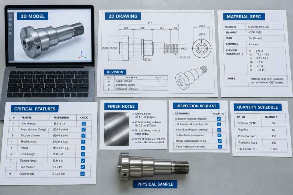
A useful RFQ normally includes a matching 3D model and controlled 2D drawing, plus material, quantity, finish, inspection, packaging, and delivery requirements. The 3D model communicates nominal geometry; the 2D drawing communicates tolerances, datums, threads, surface texture, edge conditions, notes, and acceptance requirements.
Send:
- STEP or STP solid model
- Searchable PDF drawing with part number and revision
- Native CAD file when compatibility is confirmed and it adds value
- Material grade, condition, and stock form
- Immediate quantity, expected batch size, and forecast where available
- Critical OD, ID, length, shoulder, fit, runout, thread, and groove requirements
- Off-axis features and their datum relationships
- Surface finishing, heat treatment, and masking requirements
- Inspection records and material documents required
- Packaging, destination, delivery basis, and required receipt date
State which file governs if the model and drawing conflict. Remove obsolete revisions and send every shortlisted supplier the same package. If only a sample is available, define how the sample will be measured, which wear or damage must not be copied, and who approves the reconstructed drawing.
14. How Should Precision CNC Turned Parts Be Inspected and Controlled Across Batches?
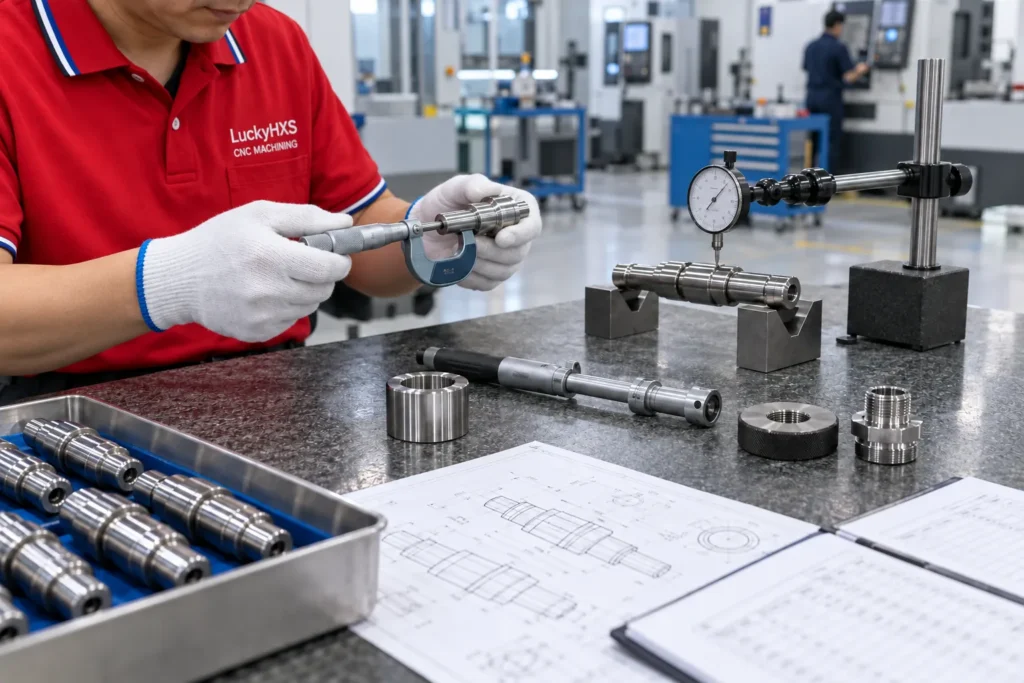
Inspection should be planned feature by feature and linked to the released drawing, datum structure, production stage, sampling rule, and required record. A machine list or general quality statement does not prove that a specific shaft, bushing, thread, or groove meets its functional requirement.
Depending on the drawing, inspection may include:
- OD, ID, length, and shoulder dimensions
- Bore size and fit
- Roundness, runout, and related-axis checks
- Thread gauges or suitable thread measurement
- Groove width, depth, and position
- Chamfer, radius, burr, and edge-condition review
- Surface texture and cosmetic criteria
- Material and surface-treatment documentation
- Cleanliness, packaging, and part identification
Before ordering, define whether you require first-part results, a first-article report, selected critical-characteristic data, a full dimensional report, material documents, or special-process records. Confirm the sample size and report format.
For repeat production, link the approved sample to the controlled drawing revision and agreed inspection plan. Ask how tool wear, offsets, setup changes, material-lot changes, machine transfers, and outside-process changes will be reviewed. The CNC machining quality inspection page provides a useful starting point; the actual acceptance plan must be confirmed for each project.
15. What Determines Price, MOQ, and Lead Time for Precision Turned Parts?
Price, MOQ, and lead time are project-specific because they depend on material, stock size, geometry, setup count, tooling, cycle time, secondary operations, finishing, inspection, documentation, quantity, packaging, and logistics. No single commercial rule applies to every custom turned part.
Major variables include:
- Material grade, condition, and purchase lot
- Part diameter, length, and material-removal volume
- Small tools, deep bores, thin walls, or long slender geometry
- Critical fits, runout, threads, and surface texture
- Number of setups and off-axis features
- Tooling, collets, soft jaws, fixtures, or gauges
- Heat treatment, plating, grinding, polishing, or cleaning
- Inspection frequency and report requirements
- Prototype quantity, repeat batch size, and forecast demand
- Packaging, destination, and required timing
Ask suppliers to separate one-time charges from unit price and identify exclusions. Request price breaks for the same controlled revision if several quantities are being considered. MOQ should be confirmed after the supplier reviews the drawing and process route.
Lead time should identify its start event and dependencies: requirement approval, material, tooling, sample production, customer approval, batch machining, outside processing, final inspection, documentation, and shipment. Read what changes CNC machining lead time and use prototype CNC machining services when the immediate goal is design or fit validation.
Request a Precision CNC Turned-Part Review
Send LuckyHXS your current 2D drawing and 3D model, or an approved sample with measurement instructions. Include the material grade, quantity, functional fits, thread and groove details, runout or datum requirements, secondary features, final finish, inspection records, packaging needs, destination, and required date. Request project-specific confirmation of process fit, tolerance capability, documentation, order quantity, and schedule before production.