
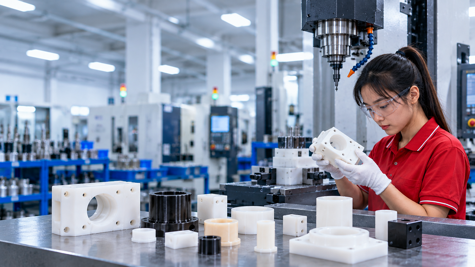
Machined plastic components are made by removing material from an engineering-plastic stock shape with controlled cutting tools. They can include housings, bushings, sleeves, spacers, manifolds, valve components, electrical insulators, fixtures, and other drawing-based parts. Unlike molded parts, they do not require a production mold before the first component can be cut.
The purchasing challenge is that “plastic” is not one predictable material. POM, nylon, PTFE, ABS, and other polymers respond differently to heat, moisture, clamping pressure, cutting force, and long-term load. A dimension that is straightforward in metal may move after a plastic part is released from a fixture or exposed to its service environment. Material grade, stock condition, geometry, machining route, inspection condition, and end use therefore need to be reviewed together.
LuckyHXS manufactures made-to-drawing plastic parts using CNC milling, turning, Swiss-type machining, and related secondary operations. Its current plastic CNC machined parts scope includes common project materials such as POM, nylon, PTFE, and ABS, with the exact grade, stock form, and project suitability confirmed during quotation. The questions below help buyers define a finished component that can be quoted and accepted without guesswork.
1. What Are Machined Plastic Components?
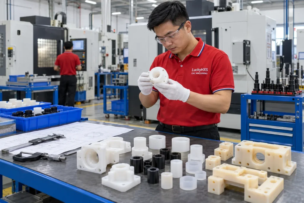
Machined plastic components are finished parts produced from plastic rod, plate, tube, or near-net stock by milling, turning, drilling, boring, reaming, threading, grooving, and related material-removal operations. Their final geometry is controlled by a drawing, 3D model, approved sample, or an agreed combination of these records.
Machining is useful when a buyer needs functional prototypes, replacement parts, low or moderate quantities, multiple material options, or dimensions that are difficult to create directly in a mold. It can also support repeat production when the geometry, material, and order economics suit the process. Common examples include:
- Bearings, bushings, sleeves, rollers, and wear pads
- Electrical insulators, sensor bodies, and connector components
- Valve seats, seals, manifolds, and fluid-handling parts
- Guides, fixtures, nests, soft jaws, and assembly aids
- Housings, covers, brackets, spacers, and structural components
- Small shafts, pins, threaded inserts, and precision turned parts
The word “machined” identifies the manufacturing route, not the performance level. A finished plastic part is only suitable when its material, geometry, tolerances, surface condition, cleanliness, and inspection basis match its application.
2. Which Types of Plastic Parts Can CNC Machining Produce?
CNC machining can produce both rotational parts and prismatic parts, provided the selected stock, tooling, workholding, and machine access suit the geometry. CNC turning is typically used for bushings, sleeves, rollers, round spacers, pins, and threaded bodies. CNC milling is commonly used for housings, plates, manifolds, fixtures, pockets, slots, and multi-face features.
A part may combine both feature families. A turned sleeve can receive wrench flats, radial holes, slots, or side threads through live tooling, turn-mill machining, or a secondary milling setup. A milled housing can require reamed bores, thread inserts, sealing faces, and protected cosmetic surfaces.
Buyers should identify relationships that must survive every setup. A bolt pattern may need to locate from a finished bore; a sealing face may need to remain square to a datum; an internal passage may need to be free of chips and burrs. These functional relationships are more important than simply naming a machine type. Review the broader custom CNC machining service when a project combines plastic machining with secondary features, inspection, and finishing coordination.
3. Which Plastics Can Be CNC Machined?
Many thermoplastics can be machined, but machinability does not mean every grade behaves the same or that one tolerance applies to all materials. Common project families include acetal/POM, nylon/PA, PTFE, ABS, polycarbonate, polyethylene, polypropylene, PET, PEEK, PPS, PEI, and filled or reinforced variants.
The correct choice depends on the finished part’s function rather than on machining convenience alone. Buyers should define:
- Operating temperature and temperature cycling
- Moisture, chemical, UV, radiation, or electrical exposure
- Required stiffness, strength, wear, friction, and creep performance
- Dimensional stability and permissible movement over time
- Flammability, food-contact, medical, or other compliance needs
- Surface finish, color, transparency, and cosmetic requirements
- Whether the material needs traceability or a specific certification record
The material callout should name the exact polymer, grade, governing specification where applicable, color, fillers, stock form, and any prohibited substitutions. A generic note such as “nylon” or “plastic” leaves too much uncertainty for quotation and acceptance.
4. How Do POM, Nylon, PTFE, and ABS Differ for Machining?
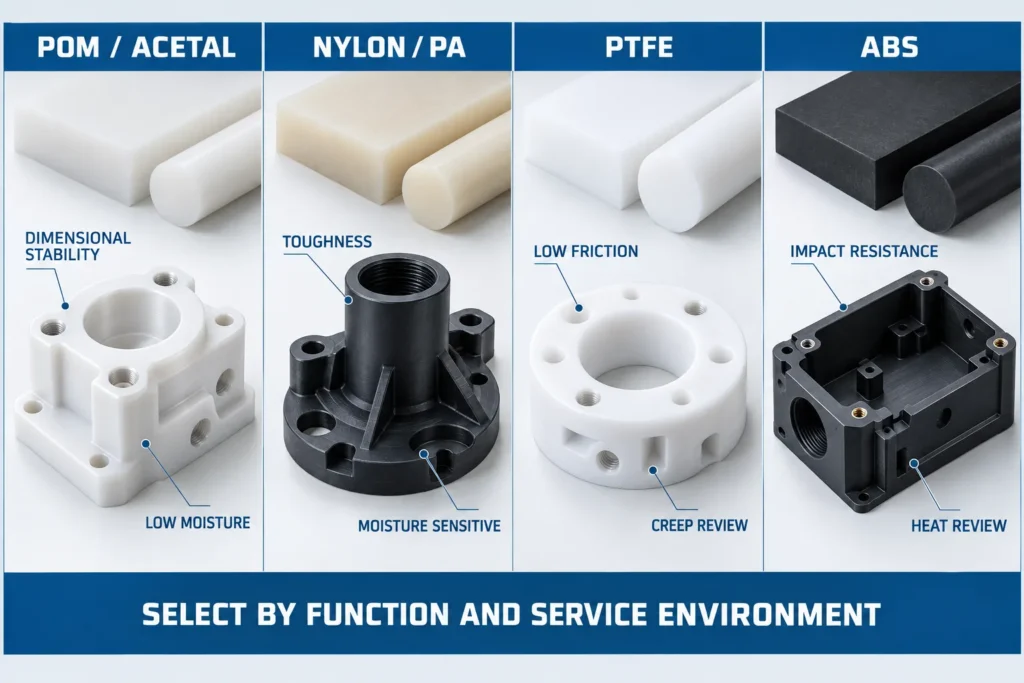
POM, nylon, PTFE, and ABS can all be machined, but they create different dimensional and application risks. The following comparison is a practical starting point, not a substitute for grade-specific engineering review.
| Material family | Common reasons to consider it | Machining and acceptance points to review |
|---|---|---|
| POM / acetal | Dimensional stability, low moisture uptake, low friction, good general mechanical performance | Internal stress, asymmetric stock removal, sharp internal corners, press fits, and final measurement temperature |
| Nylon / PA | Toughness, wear resistance, impact performance, and bearing applications | Moisture absorption, conditioning state, dimensional movement, thin-wall distortion, and service humidity |
| PTFE | Low friction, chemical resistance, electrical insulation, and broad service uses | Low stiffness, creep, clamping deformation, burr control, surface waviness, and realistic tolerance expectations |
| ABS | Impact resistance, ease of machining, cost-sensitive fixtures, covers, and housings | Heat sensitivity, thin walls, stress cracking risk, cosmetic surfaces, and compatibility with coolants or cleaning agents |
High-performance plastics and filled grades may require different tools, speeds, chip-control methods, or inspection conditions. Mitsubishi Chemical Group’s guide to machining plastic parts notes that tool choice, heat, coolant compatibility, and material-specific practices affect the finished result. The supplier should confirm the exact requested grade and stock availability rather than silently substituting a similar-looking material.
5. How Should the Material Grade and Stock Condition Be Specified?
Specify the exact material grade, product form, condition, and required evidence because polymer family names alone do not control performance. Two materials sold under the same generic name can differ in molecular structure, fillers, reinforcement, colorants, processing history, or residual stress.
A useful material requirement may include:
- Resin family and exact grade or approved equivalent
- Unfilled, glass-filled, carbon-filled, bearing grade, or other formulation
- Rod, plate, tube, or other stock form and any orientation requirement
- Color and cosmetic acceptance standard
- Annealed, stress-relieved, conditioned, or as-supplied state
- Lot traceability, certificate of conformance, or material report requirement
- Restricted-substance or application-specific documentation
- Rules for substitutions and the person authorized to approve them
Stock size also matters. A finished part cut from an oversized plate may require heavy, unbalanced material removal, increasing movement risk and waste. Material cut from the outer region of a molded or extruded stock shape may behave differently from material near its center. Ask the supplier to identify the proposed stock form and any stress-relief or conditioning stage that affects final dimensions.
6. What Tolerances Can Machined Plastic Components Hold?
There is no responsible universal tolerance for all machined plastic components. Achievable control depends on the polymer and grade, stock condition, feature size, wall thickness, geometry, workholding, cutting sequence, temperature, moisture state, quantity, inspection method, and the condition in which the part is accepted.
Instead of applying one tight tolerance to the entire drawing, identify the dimensions that protect function. These may include a bearing diameter, sealing face, mounting pattern, shoulder location, bore-to-hole position, thread fit, or assembled height. Use wider tolerances for clearance, stock-removal, or nonfunctional cosmetic features where the design permits.
The drawing should also define the acceptance condition. State whether dimensions apply immediately after machining, after conditioning, at a specified reference temperature, after a finish or cleaning step, or after the part has rested free of the fixture. For flexible components, define how the part is supported during measurement. A supplier should confirm capability feature by feature from the actual drawing, not from a general machine specification.
7. Why Do Plastic Parts Warp or Change Size After Machining?
Plastic parts can move because machining releases residual stress and adds localized heat while the material has lower stiffness and different thermal or moisture behavior than metal. Heavy one-sided material removal, high clamping force, dull tools, poor chip evacuation, thin walls, and uneven cooling can increase the risk.
Moisture-sensitive polymers may also change size as environmental humidity changes. Other plastics can creep under sustained load or relax after they are removed from a vise or fixture. Curbell Plastics’ plastic machining guidelines emphasize stress-relieved stock, heat management, and intermediate stress relief where substantial material removal makes it necessary.
A project-specific control plan may use:
- Stress-relieved stock selected for the application
- Balanced or staged material removal
- Rough machining followed by a rest or approved stress-relief stage
- Low-distortion workholding and adequate part support
- Sharp tools, suitable cutting parameters, and reliable chip evacuation
- Semi-finishing before a light final pass
- Free-state inspection after a defined stabilization period
- Environmental conditioning before final measurement where required
These controls should be agreed before production because an extra stabilization or stress-relief stage affects cost, scheduling, and inspection timing.
8. How Should Thin Walls, Deep Pockets, and Large Flat Parts Be Designed?
Thin walls, deep pockets, and large flat parts should be designed around stiffness, tool access, balanced stock removal, and the condition in which the part must function. A wall that appears stable inside a fixture may spring after unclamping, while a broad plate can bow when material is removed from only one face.
Practical review points include:
- Increase wall thickness or add ribs where function permits
- Avoid abrupt thickness transitions and unsupported tall walls
- Use realistic internal corner radii that fit available cutters
- Reduce unnecessary pocket depth and long-reach tool exposure
- Provide stable clamping and datum surfaces outside critical cosmetic areas
- Balance material removal across opposing faces where possible
- Separate functional tolerances from appearance requirements
- Define whether flatness or profile applies in a free or restrained condition
Do not automatically redesign a part to make it easier to machine. The supplier should identify which features create risk, explain the proposed route, and obtain buyer approval before changing controlled geometry. A small validation lot may be appropriate when the design or material response has not yet been proven.
9. How Should Holes, Threads, Press Fits, and Burrs Be Specified?
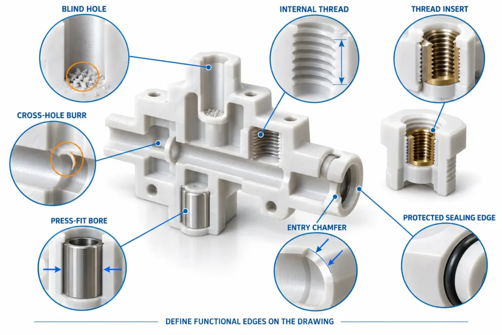
Holes, threads, press fits, and burr requirements should be defined with measurable functional information rather than nominal size alone. Plastic can deflect during drilling or gauging, and aggressive deburring can round a sealing edge, enlarge a hole, or damage a thread entry.
For holes and threads, specify the diameter or thread standard, depth, through or blind condition, positional relationship, usable thread length, entry chamfer, relief, mating part, and inspection method. State whether inserts are required and whether they are installed before or after final inspection. Press fits need the mating component, service temperature, assembly method, and acceptable retention or insertion criteria.
Mark edge conditions feature by feature. Identify edges that may be broken, sealing or locating edges that must be protected, cross-hole intersections that must be free of internal burrs, and passages that must be clean. The deburring services page provides a starting point for discussing edge access and inspection, but the actual requirement must be defined on the project drawing.
10. When Is CNC Machining Better Than Injection Molding?
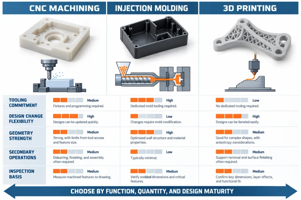
CNC machining is often the better route when quantities are low or moderate, the design may change, mold lead time is not justified, a stock-shape material is required, or critical features benefit from direct machining. Injection molding becomes more attractive when the design is stable, volume supports dedicated tooling, and the molded geometry and material meet the finished-part requirements.
Compare the complete delivered component, not only the primary shaping operation. A molded part may still need machining, inserts, trimming, finishing, inspection, or assembly. A machined part may require more material and cycle time but avoid mold investment and allow faster controlled revisions.
Important comparison questions include:
- What is the prototype quantity, first order, and expected repeat demand?
- Is the design stable enough to release production tooling?
- Does the required resin exist in suitable stock and molding grades?
- Which features would still require secondary machining?
- How will shrinkage, warp, parting lines, ejector marks, and gate locations affect function?
- What inspection and documentation apply to each route?
- Who owns, maintains, stores, and revises any dedicated mold?
The correct decision can change over the product life cycle. A buyer may machine early validation parts, update the design, and then reassess molding after demand and geometry stabilize.
11. When Is CNC Machining Better Than 3D Printing?
CNC machining is generally preferable when the buyer needs properties associated with commercial stock shapes, machined surface control, accurate bores or threads, predictable datum relationships, or a component that closely represents a later subtractive-production part. 3D printing is often useful for fast shape studies, internal geometries that cannot be cut, or early prototypes where appearance and fit matter more than final material behavior.
The two processes should be compared using the intended function. A printed part may use a different material structure and surface condition from a machined stock-shape component. A machined prototype may be more representative for sealing, bearing, electrical, or mechanical tests, but it can waste more material and require additional setups.
Ask which questions the prototype must answer: geometry, assembly, load, wear, fluid compatibility, temperature, appearance, or production readiness. If a process or material changes after validation, document which tests need to be repeated. Neither process is automatically best for every component.
12. How Should Machined Plastic Components Be Inspected?
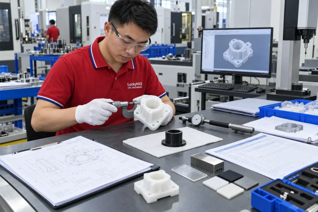
Machined plastic components should be inspected from the drawing’s functional characteristics and under defined environmental and support conditions. The plan should state what is measured, at which production stage, against which revision, with what method, at what frequency, and in what report format.
Depending on the part, inspection may include:
- Outside and inside diameters, lengths, shoulders, and wall thickness
- Bore size, depth, taper, roundness, and relation to outside features
- Flatness, profile, parallelism, and hole-pattern position
- Internal and external threads, inserts, and usable thread length
- Sealing surfaces, cosmetic zones, burr condition, and cleanliness
- Material identity, color, lot, and requested supporting records
- Final condition after conditioning, cleaning, or secondary processing
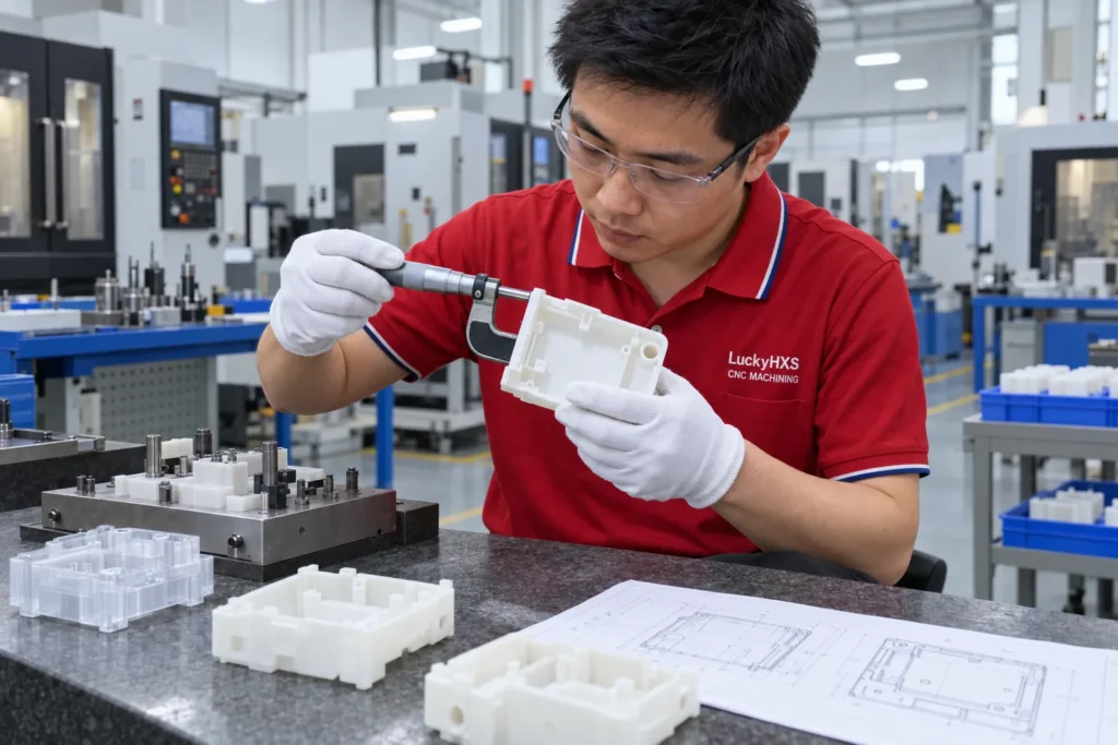
Use a method that does not distort the part. Excessive micrometer force, an unsuitable fixture, or a rigid clamping arrangement can create a misleading result. Define temperature, humidity, conditioning time, and free-state or restrained measurement where these variables affect acceptance. The CNC machining quality inspection page describes available inspection planning concepts; the final plan must remain specific to the drawing and application.
13. How Can Buyers Evaluate a Machined Plastic Components Manufacturer?
Buyers should evaluate a manufacturer by its ability to control the complete plastic-part route, not merely by counting CNC machines. A capable response explains material sourcing, stock condition, workholding, cutting strategy, heat and chip control, secondary operations, inspection, revision control, packaging, and repeat-order management.
Ask the supplier to review one representative drawing and explain:
- Which material grade and stock form it proposes
- Which features create distortion, burr, tool-access, or measurement risk
- The proposed setup sequence and datum strategy
- How thin walls and flexible features will be supported
- Whether roughing, stabilization, or conditioning is required
- How critical features will be measured without deforming the part
- Which work is performed internally and which is subcontracted
- What records, samples, or first-part results are included
- How obsolete drawings, deviations, and engineering changes are controlled
- How finished parts are protected from scratches, contamination, or deformation
Evidence should match the project risk. A generic equipment list or quality statement does not prove that a supplier can control a specific nylon housing, PTFE sleeve, or thin POM manifold. Review the drawing, sample plan, and acceptance records before releasing repeat production.
14. What Files and Information Are Needed for a Useful RFQ?
A useful RFQ needs the controlled geometry, exact material requirement, quantities, operating conditions, and acceptance criteria for the finished component. The supplier should not have to infer functional requirements from a rendering or a sample photograph.
Send the following where applicable:
- Searchable 2D drawing with part number, units, and revision
- Matching STEP or STP model and a rule for resolving model-drawing conflicts
- Exact polymer grade, color, filler, stock condition, and substitution rules
- Prototype quantity, first order, price-break quantities, and demand forecast
- Critical dimensions, datums, fits, threads, edge conditions, and surface requirements
- Operating temperature, humidity, chemical, electrical, wear, or load conditions
- Cleaning, marking, secondary operation, and packaging requirements
- First-part, dimensional, material, process, or compliance records required
- Delivery destination, requested receipt date, and shipment assumptions
- Approved sample information and the authority for accepting deviations
If only a physical sample exists, define which wear, damage, distortion, or contamination must not be copied. Agree how the sample will be measured, how uncertainty will be documented, and who approves the reconstructed drawing before production.
15. What Determines Price, MOQ, and Lead Time?
Price, minimum order quantity, and lead time are project-specific because they depend on the complete manufacturing and acceptance route. No fixed number can responsibly apply to every machined plastic component.
Major variables include:
- Polymer grade, stock form, stock size, availability, and purchase quantity
- Material yield and the amount of stock removed
- Programming, setup count, fixtures, and special tooling
- Machining time, tool access, chip control, and handling risk
- Thin walls, deep pockets, tight fits, threads, and related-feature control
- Roughing, stabilization, conditioning, or stress-relief stages
- Inserts, deburring, cleaning, marking, and other secondary work
- Inspection time, gauges, sample size, reports, and material records
- Prototype approval, engineering changes, and repeat-order stability
- Packaging, destination, freight basis, and outside-process scheduling
Ask the supplier to separate one-time charges from recurring unit price, identify assumptions and exclusions, and provide price breaks for realistic quantities. Lead time should state its starting event and dependencies, including drawing approval, material receipt, sample acceptance, production, inspection, packaging, and shipment. A low quotation is not comparable if it omits a required material grade, inspection record, protected edge, secondary operation, or packaging method.
Request a Machined Plastic Components Review
Send LuckyHXS your current 2D drawing and matching 3D model, or an approved sample with clear reconstruction and acceptance instructions. Include the exact plastic grade, stock condition, quantities, operating environment, critical features, final surface and edge requirements, inspection records, packaging, and delivery destination.
LuckyHXS can review whether the part is better suited to CNC milling, turning, Swiss-type machining, or a combined route and identify open material, workholding, distortion, burr, and inspection questions before quotation. Start with the plastic CNC machined parts page or submit your project through the contact page.