

An aluminum CNC milling service should turn a controlled drawing or 3D model into a finished part whose alloy, geometry, datums, edge conditions, finish, and inspection plan work together. The work may include drawing review, material confirmation, milling, drilling, tapping, deburring, surface finishing, inspection, documentation, packaging, and support for repeat orders—not only cutting a block of aluminum.
LuckyHXS supplies made-to-drawing and sample-based CNC components for industrial buyers. Aluminum grades recorded in the company material scope include 6061, 6063, 7075, 2024, and 5052; the exact temper, stock form, availability, machining route, finish, and acceptance method must be confirmed for each project. For the broader commercial scope, see the aluminum CNC machining service and custom CNC milling service pages. The questions below help buyers prepare an RFQ that a supplier can evaluate without guessing.
1. What Is Included in an Aluminum CNC Milling Service?
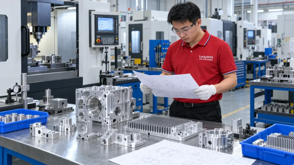
A complete service begins by defining the finished deliverable. The supplier reviews the governing files, alloy and temper, quantities, critical features, surface condition, finishing, inspection records, packaging, and requested schedule. It then proposes a manufacturing route and identifies requirements that need clarification before material and tooling are committed.
Depending on the drawing, the route may include:
- Sawing or preparing plate, block, or other stock
- CNC face milling, pocketing, profiling, drilling, boring, reaming, and tapping
- Multiple setups or multi-face machining
- Special workholding for thin, delicate, or irregular geometry
- Deburring, cleaning, marking, and approved secondary operations
- Anodizing, blasting, polishing, or another project-specified finish
- Feature-based inspection and agreed documentation
- Protection of cosmetic faces, sealing areas, threads, and sharp functional edges
The quotation should state which operations are included and which remain outside the supplier’s scope. A low unit price is not comparable with another offer if finishing, inspection, documentation, or packaging has been excluded. Review the CNC milling parts page when the purchasing requirement concerns finished components rather than machining time alone.
2. Which Aluminum Parts Are Well Suited to CNC Milling?
Milling is usually appropriate when the main geometry is prismatic or organized around faces rather than a rotational axis. Typical candidates include housings, enclosures, brackets, mounting plates, manifolds, fixture blocks, heat sinks, cold plates, sensor bodies, covers, and parts with pockets, slots, bolt patterns, angled faces, or contoured surfaces.
The process is especially useful when several features must maintain controlled relationships to common datums. For example, a housing may require a sealing face, bearing bore, connector opening, and mounting-hole pattern to locate correctly in the final assembly. A 3D model can describe the shape, but the drawing should identify which relationships actually control function.
Not every aluminum part belongs on a mill. Predominantly cylindrical shafts, sleeves, spacers, and bushings may be better suited to turning. A round component with flats, cross holes, radial ports, or slots may justify a combined route. The supplier should select the process from the complete geometry rather than from the keyword used in the RFQ. The article on CNC turning versus CNC milling explains the basic process distinction.
3. Which Aluminum Alloy and Temper Should I Specify?
Specify the exact alloy, temper or condition, governing standard, and stock form required by the application. “Aluminum” alone is not a complete material callout. Two grades can look similar while differing in strength, corrosion behavior, fatigue performance, forming response, weldability, finishing response, availability, and price.
Common decision points include:
- 6061: often considered for general industrial housings, brackets, fixtures, adapters, and machined structural parts when a balanced set of properties is needed.
- 6063: often associated with profiles and selected appearance-oriented or light structural applications; the available stock form and temper should be checked.
- 7075: considered where higher mechanical strength is important, but corrosion behavior, finishing, material cost, and application conditions require review.
- 2024: may be selected for strength and fatigue-related requirements, while corrosion protection and joining requirements deserve attention.
- 5052: widely used in sheet-based fabrication and corrosion-sensitive applications; confirm whether the intended stock form and machined geometry make it a practical milling choice.
Do not substitute one grade because it is easier to purchase or machine. If alternatives are allowed, state which properties must remain equivalent and who has approval authority. For a focused comparison, use the 6061 versus 7075 aluminum guide.
4. Should the Supplier Use 3-Axis, 3+2, or 5-Axis Milling?
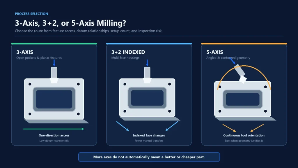
The appropriate route depends on feature access, datum relationships, setup count, quantity, inspection access, and the risk created by re-clamping. A conventional 3-axis setup can be efficient for plates, open pockets, and features accessible from one direction. Indexed multi-face work may reduce manual transfers. Simultaneous 5-axis machining can be useful for contoured surfaces, angled features, or geometry whose relationships benefit from continuous tool orientation.
More axes do not automatically produce a better or cheaper part. A simple component may be most stable and economical in conventional setups. A complex part may still need special fixtures, long-reach tools, separate finishing operations, or inspection between stages. Ask the supplier to explain:
- Proposed setup sequence
- Datum and workholding strategy
- Features completed in each setup
- How positional relationships survive transfers
- Where special tooling or secondary machining is required
- How critical features will be inspected
The explanation is more useful than a machine-model list. It lets the buyer compare whether each supplier has priced the same finished scope.
5. What Tolerances Can Aluminum CNC Milling Hold?
There is no single tolerance that applies to every aluminum milled part. Capability depends on the alloy and temper, feature size, wall stiffness, stock condition, tool access, setup strategy, thermal stability, finishing sequence, and inspection method. A tolerance that is practical on a short bore in a rigid block may be unrealistic on a wide free-standing wall or a large plate after heavy material removal.
Define tolerance feature by feature. Give special attention to:
- Fits between bores, pins, bearings, and mating components
- Hole location relative to functional datums
- Flatness of sealing, mounting, and thermal-interface faces
- Parallelism or perpendicularity between assembly surfaces
- Position of threaded ports and cross passages
- Profile requirements on contoured surfaces
- Dimensions that apply after anodizing or another finish
Avoid applying the tightest tolerance to every dimension. Unnecessary precision can add setups, slow machining, require additional inspection, and increase scrap risk without improving function. Ask the supplier to identify which callouts are difficult, ambiguous, or dependent on the final finishing condition. The guide to how tight tolerances affect CNC machining cost provides additional purchasing context.
6. How Should Datums, Flatness, and Hole Position Be Controlled?
The datum scheme should reflect how the part is assembled and used. Select stable, accessible features that can be established during machining and recreated during inspection. A decorative outer face may be a poor datum if the functional assembly actually locates from a mounting plane, bore, and side face.
For a housing or manifold, a practical drawing may establish a primary mounting or sealing face, a secondary locating feature, and a tertiary orientation feature. Hole patterns, bores, pockets, and ports can then be related to that structure. This is usually clearer than chaining many coordinate dimensions from unrelated edges.
State how the part should be evaluated when free-state geometry matters. A thin plate may appear flat while clamped but relax after removal. Inspection fixtures must not force a distorted part into compliance. When flatness, parallelism, or true position controls assembly, define the datum reference frame, measurement condition, and acceptance stage on the released drawing.
7. Why Do Thin Walls, Deep Pockets, and Large Plates Distort?
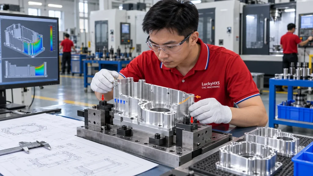
Aluminum parts can move because material removal changes the balance of residual stress, while cutting force, heat, fixture pressure, and low wall stiffness temporarily deform the workpiece. The risk rises with thin walls, deep pockets, high material removal, long tool reach, asymmetric geometry, large plates, and features machined far from support.
A suitable control plan may use staged roughing and finishing, balanced material removal, stable stock orientation, purpose-designed fixtures, reduced clamping force, supported walls, shorter tools, revised machining sequences, or time between operations. The correct combination is part-specific. The supplier should also inspect the released part in the condition that matters, not only while it is constrained in a fixture.
Buyers can reduce ambiguity by marking which walls, faces, and ribs are functional. If a wall merely provides clearance, it may not need the same control as a sealing face or bearing support. Where design changes are possible, increasing stiffness, reducing unsupported height, opening tool access, or separating cosmetic and functional requirements can improve both manufacturability and measurement confidence.
8. Can Deep Cavities, Small Internal Radii, Undercuts, and Sharp Corners Be Milled?
They can often be produced, but each feature has a manufacturing consequence. A rotating cutter leaves an internal radius; it cannot create a mathematically sharp inside corner. Smaller radii require smaller tools, which are less rigid and may need slower, shallower passes. Deep cavities increase tool overhang, deflection, vibration, chip-evacuation difficulty, and surface variation.
Undercuts need suitable access and may require special cutters, another setup, or a different process. Blind features must leave space for tool entry and chip removal. If a mating rectangular component needs corner clearance, a relief feature may be more practical than an extremely small radius.
For every difficult feature, ask whether its geometry is functional. If it is, define the mating condition and acceptance criterion. If it is not, permit a practical radius, relief, or access change. A supplier should flag tool-inaccessible geometry before quoting rather than assuming that the CAD model alone is manufacturable.
9. How Should Small Holes, Threads, Inserts, and Burrs Be Specified?
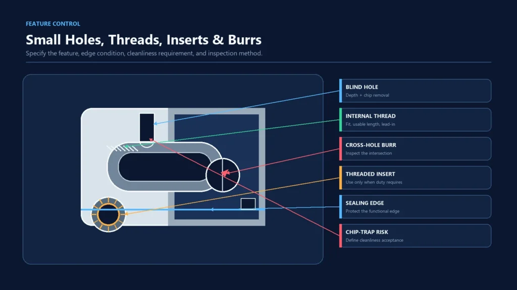
Small features require more information than nominal diameter. For holes, specify depth, through or blind condition, positional requirement, surface or fit requirement, and whether an intersecting passage must be burr-free and clean. For threads, state the standard, size, pitch, class or fit, usable length, entry chamfer, thread relief, and gauge or measurement requirement.
Direct aluminum threads may be suitable for many assemblies. Repeated disassembly, high tightening loads, wear, or service conditions may justify a threaded insert, but an insert is not automatically necessary. Define the actual duty and obtain engineering approval before changing the design.
Generic notes such as “deburr all edges” do not distinguish a harmless handling edge from a sealing edge, thread lead-in, precision bore, or datum shoulder. Mark which edges may be broken, which must remain sharp, and which internal intersections require inspection. The supplier should remove chips and unwanted burrs without enlarging holes, rounding controlled features, or damaging cosmetic surfaces. See the deburring services page for feature-specific review points.
10. What Surface Finish Should Be Specified on Milled Aluminum?
Specify finish by function and by area. An as-machined surface may be acceptable for hidden clearance faces, while sealing faces, bearing seats, thermal interfaces, sliding surfaces, and cosmetic panels may need different texture or appearance controls. If surface texture matters, identify the relevant face and state a measurable requirement rather than using “smooth” or “good finish.”
Tool marks can remain visible after anodizing or blasting. A cosmetic requirement should therefore define the viewing surface, grain or texture expectation, acceptable color range, rack or contact areas, scratch criteria, and whether different batches must be visually matched. Separate appearance requirements from dimensional ones so inspectors know how each feature is accepted.
LuckyHXS material records indicate that aluminum projects may be reviewed for anodizing and sandblasting, with exact color and coating details confirmed during quotation. Other finish options should only be included when the project-specific supplier confirms them. Review the surface finishing service page when preparing the finish specification.
11. How Do Anodizing and Blasting Affect Dimensions and Appearance?
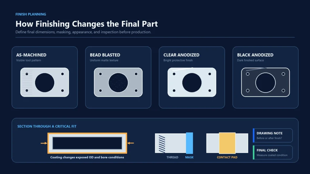
Finishing is part of the manufacturing plan, not a cosmetic note added after machining. Anodizing changes exposed surfaces and can affect bores, threads, bearing seats, locating fits, sealing faces, and electrical contact areas. The drawing should state whether dimensions apply before or after finishing, which areas require masking, and which features need final inspection in the coated condition.
Bead blasting can create a more uniform visual texture, but it does not correct geometry or guarantee that all machining marks disappear. Anodized color can vary with alloy, temper, surface preparation, geometry, coating process, and batch. If color matching is important, define a controlled reference and the acceptance method rather than relying on a color name alone.
Coordinate machining allowance, masking, coating, and final measurement before production. Do not let the machine shop and finishing source work from different revision assumptions. The guides on how anodizing affects holes, threads, and fits and whether drawing dimensions apply before or after finishing address these points in more detail.
12. How Should Aluminum CNC Milled Parts Be Inspected?
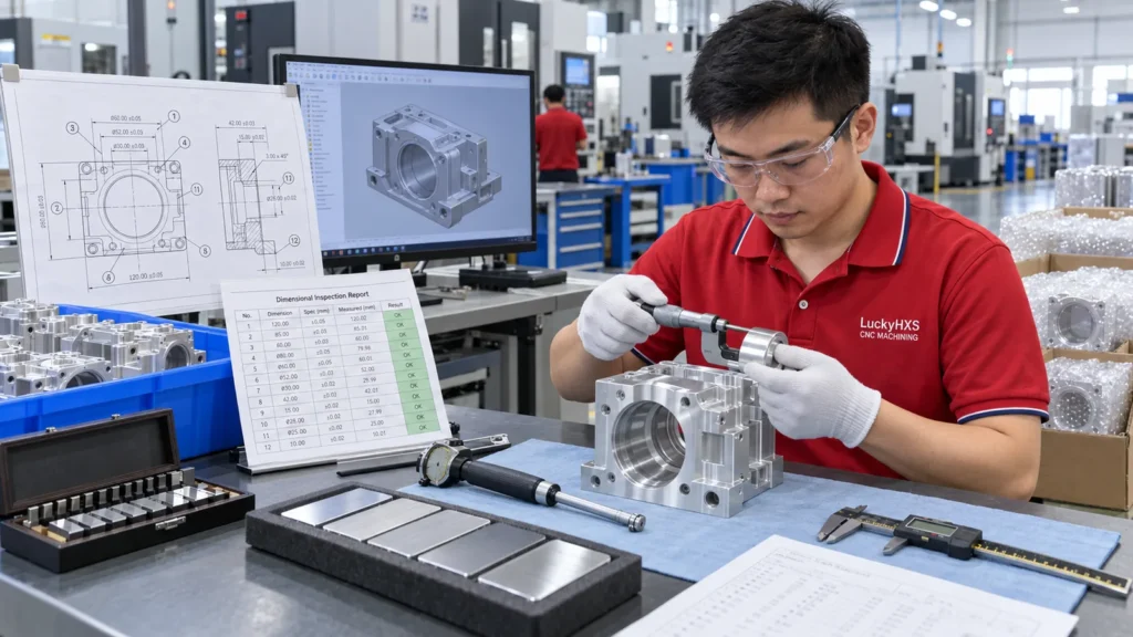
Inspection should follow the drawing’s functional characteristics. The plan needs to identify what is measured, at which production stage, against which revision, by which method, at what frequency, and in what report format. A list of measuring equipment does not by itself prove that the important features will be controlled.
Depending on the part, inspection may include:
- Overall dimensions, pocket depths, wall thicknesses, and step heights
- Hole size, location, angular orientation, and thread condition
- Flatness, parallelism, perpendicularity, and profile
- Bore-to-datum and port-to-passage relationships
- Sealing-face, bearing-seat, or thermal-interface condition
- Surface texture and cosmetic acceptance
- Final dimensions after finishing
- Burr, cleanliness, identification, and packaging condition
Agree before ordering whether you require first-part results, a first-article report, selected critical-characteristic data, a full dimensional report, material evidence, finish records, process certificates, or photographs. The exact document package is project-specific and should be priced in the quotation. The CNC machining quality inspection page provides a useful framework for this discussion.
13. Can a Prototype Be Transferred Directly to Repeat Production?
A successful prototype proves only the conditions under which that sample was made and accepted. Repeat production requires a controlled revision, confirmed material and temper, stable workholding and tooling, an approved process route, and an inspection plan that can detect drift across lots.
Link sample approval to the exact part number, drawing revision, 3D model, finish specification, inspection record, and approved deviations. If a design change follows testing, issue a new revision and state whether another sample, partial revalidation, or new first-article approval is required. Do not request “same as last time” without identifying the governing revision.
Also confirm how changes in stock source, machining setup, outside finishing, tooling, inspection method, or packaging will be reviewed. The objective is not to freeze every shop decision; it is to ensure that changes affecting fit, function, or acceptance receive the appropriate approval. See prototype CNC machining services for the earlier validation stage.
14. What Files and Information Are Needed for an Accurate Quote?
Send enough information to define the finished component and its acceptance basis. A matching 3D model and searchable controlled 2D drawing are ideal: the model communicates nominal geometry, while the drawing communicates tolerances, datums, material, finish, edge conditions, notes, and inspection requirements.
Include, where applicable:
- Part number, drawing revision, and governing file
- STEP or STP solid model plus a controlled PDF drawing
- Exact aluminum alloy, temper, standard, and stock-form requirement
- Prototype quantity, immediate order quantity, and expected repeat demand
- Critical dimensions, fits, hole positions, threads, and datum relationships
- Thin walls, deep pockets, sealing faces, cosmetic areas, and protected edges
- Surface texture, anodizing or blasting requirements, color, and masking
- Inspection records, material evidence, and other required documents
- Packaging, identification, destination, delivery basis, and requested receipt date
If the model and drawing conflict, state which file governs. If only a physical sample is available, define how it will be measured, which wear or damage must not be copied, who approves the reconstructed drawing, and how final acceptance will be established.
15. What Affects Price, MOQ, and Lead Time?
Price, minimum order quantity, and lead time are project-specific. They depend on the complete manufacturing and acceptance route, not only part volume or machine time. LuckyHXS does not have a verified universal MOQ, fixed lead-time promise, or standard price that should be applied to every aluminum milling project.
Major cost and scheduling variables include:
- Alloy, temper, stock size, availability, and purchase quantity
- Material-removal volume and the amount of purchased stock discarded
- Number of setups and difficulty of workholding
- Thin walls, deep pockets, long tool reach, small internal radii, and undercuts
- Tight tolerances and relationships across multiple faces
- Special cutters, fixtures, probes, or gauges
- Deburring, cleaning, anodizing, blasting, polishing, or masking
- First-article, dimensional, material, or finish documentation
- Order quantity, repeatability of demand, and revision stability
- Packaging, destination, shipment method, and outside-process scheduling
Ask the supplier to separate one-time charges from unit price and to identify quotation assumptions and exclusions. Lead time should state its start event and dependencies, such as drawing approval, material receipt, tooling, sample acceptance, finishing, inspection, packaging, and shipment. The article on CNC machining lead time explains why two apparently similar parts can have different schedules.
Request an Aluminum CNC Milling Review
Send LuckyHXS your current 2D drawing and matching 3D model, or an approved sample with clear reconstruction and acceptance instructions. Include the aluminum alloy and temper, quantities, critical features, final finish, inspection records, packaging, and required receipt date.
The review should return a project-specific manufacturing route, open technical questions, quotation assumptions, included operations, and acceptance plan. Use the contact page to submit your aluminum CNC milling RFQ and drawings.