
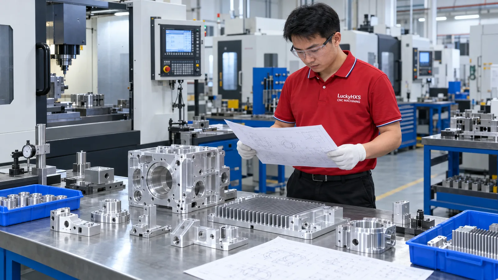
CNC milling is a subtractive manufacturing process in which a computer-controlled machine moves a rotating cutting tool relative to a workpiece to remove material. It can create flat faces, pockets, slots, holes, threads, contours, and multi-face features in metals and engineering plastics. The finished result depends on more than the machine: the drawing, CAD model, toolpaths, material, workholding, cutting tools, inspection plan, and finishing route must all agree.
LuckyHXS supplies made-to-drawing and sample-based CNC components for industrial and OEM projects. Its project scope may include CNC milling, drilling, boring, reaming, tapping, deburring, finishing coordination, inspection, documentation, packaging, and support for repeat production. Buyers who already have a drawing can review the custom CNC milling service and CNC milling parts pages. The questions below explain the process itself and help determine whether milling fits a particular part.
1. What Is CNC Milling?
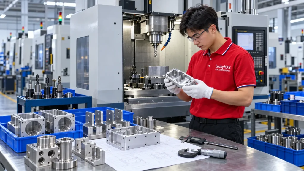
CNC milling is a machining process that uses a rotating, multi-edge cutter to remove material from a secured workpiece. “Subtractive” means the final shape is produced by cutting away material from plate, block, bar, a near-net blank, or another approved stock form. Computer instructions control the relative motion of the tool and workpiece along defined axes.
The process is especially useful for parts organized around faces rather than one rotational centerline. Typical examples include housings, brackets, manifold blocks, base plates, covers, fixture components, sensor enclosures, heat sinks, valve bodies, and mold or tooling inserts. Milling can also add flats, keyways, cross holes, ports, and bolt patterns to a turned component.
CNC milling is not the name of one machine, one tolerance, or one quality level. A simple three-axis machining center and a simultaneous five-axis machine both perform CNC milling, but they solve different access and setup problems. The achievable result must be evaluated from the actual part geometry, material, feature relationships, quantity, tool access, workholding, finishing, and inspection requirements.
2. What Does CNC Stand For?
CNC stands for computer numerical control. The term describes how machine motion and functions are controlled through programmed numerical instructions. Instead of an operator guiding every cutting movement by hand, the machine follows a prepared program that commands axis positions, feed rates, spindle speed, tool changes, coolant, and other operations.
Automation does not remove engineering judgment. A programmer still needs to decide how the part will be oriented, which cutters will reach each feature, how much material will be removed at each stage, how the workpiece will be held, and how collisions will be avoided. Operators set the machine, load tools and stock, verify offsets, monitor cutting, manage chips, and inspect the output. Engineers and inspectors determine whether the released part meets the drawing.
The same CNC principle is used in turning, grinding, electrical-discharge machining, and other manufacturing processes. What makes CNC milling distinct is the use of a rotating cutter to generate milled geometry. For a broader overview of these process families, see What Is CNC Machining?.
3. How Does CNC Milling Work From CAD to a Finished Part?
A controlled 3D model usually defines nominal geometry, while a 2D drawing communicates tolerances, datums, threads, surface texture, edge conditions, material, finish, and inspection requirements. A manufacturing engineer reviews both before deciding how the part will be made.
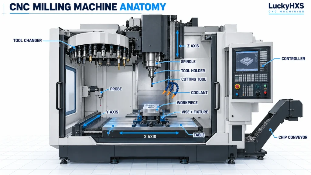
A typical workflow is:
- Review the requirements. Confirm the governing revision, material, quantity, critical features, finish, documents, and delivery basis.
- Plan the process. Select stock, machine type, setup sequence, workholding, datums, cutters, and inspection stages.
- Create CAM toolpaths. Software converts machining intent into roughing, semi-finishing, drilling, and finishing paths.
- Post-process the program. The CAM output is translated into machine-compatible instructions, often called G-code.
- Set up and verify. The operator installs tools and fixtures, locates the workpiece, establishes offsets, and checks the program safely.
- Machine the part. Material is removed in planned stages while chips, heat, tool wear, and part stability are controlled.
- Inspect and finish. Required features are measured, burrs are removed, and approved heat treatment, surface finishing, cleaning, or marking is completed.
A program can repeat motion accurately, but it cannot repair an ambiguous drawing or unsuitable setup by itself. Controlled files and a practical process plan remain essential.
4. What Are the Main Parts of a CNC Milling Machine?
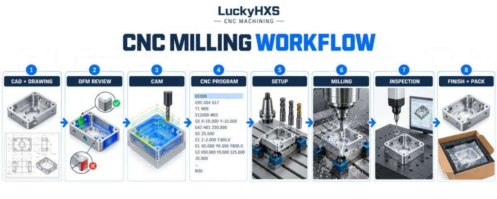
Machine designs vary, but most CNC milling systems contain the same functional groups. The spindle rotates the tool through a tool holder. Linear or rotary machine axes control the relative position and orientation of the cutter and workpiece. A table, vise, fixture, chuck, or custom workholding device secures the stock. The controller interprets the program and coordinates motion, spindle functions, tool changes, and auxiliary systems.
Many production machines also use an automatic tool changer and tool magazine so different cutters can be used within one program. Coolant or air assists cutting and chip evacuation where appropriate. Enclosures contain chips and fluid, while probes or tool setters may help locate the workpiece, establish offsets, or verify tools. Conveyors and filtration systems manage chips and coolant during longer cycles.
Machine structure matters because cutting forces travel through the tool, spindle, axes, workpiece, fixture, and machine frame. Wear, vibration, thermal change, poor clamping, excessive tool overhang, or trapped chips can affect the part even when the program is correct. A capability discussion should therefore address the complete setup, not only the machine brand or advertised axis travel.
5. What Operations Can CNC Milling Perform?
CNC milling can combine several operations in one manufacturing route. Face milling creates broad flat surfaces. Peripheral or profile milling forms outside walls and contours. Pocketing removes material inside a boundary, while slotting creates channels, keyways, and narrow openings. Three-dimensional contouring can produce curved surfaces when the cutter and machine path provide suitable access.
Machining centers also perform hole-making operations. These may include spot drilling, drilling, boring, reaming, countersinking, counterboring, and tapping. Thread milling can create selected internal or external threads when the geometry, tool, and access permit. Chamfering tools break specified edges, and engraving or marking may be added when agreed.
Not every visible feature should be machined in one setup or by milling alone. Deep bores, fine surface requirements, narrow internal corners, special threads, heat-treated surfaces, or hard-to-reach undercuts may require dedicated tooling or a secondary process. A rotational blank may be turned first and milled later, or it may be produced through an integrated turn-mill route. The drawing should define the finished feature; the supplier should explain the proposed sequence and included operations.
6. What Is the Difference Between CNC Milling and CNC Turning?
The simplest distinction is which element provides the primary cutting rotation. In milling, the cutting tool rotates while the workpiece is secured or repositioned. In turning, the workpiece rotates while a cutting tool forms diameters, faces, bores, grooves, and threads around an axis.
Milling generally fits parts dominated by flat faces, pockets, slots, hole patterns, angled surfaces, and non-rotational contours. Turning generally fits shafts, pins, sleeves, bushings, spacers, threaded bodies, and other axis-centered components. This is a geometry-based distinction, not a rule that every part belongs entirely to one process.
Many components need both. A connector body may require turned diameters and threads plus wrench flats and cross holes. It could be completed on a turn-mill machine, transferred from a lathe to a machining center, or made by another combined route. The preferred method depends on feature relationships, access, setup risk, quantity, equipment, tooling, and inspection. The CNC turning versus CNC milling guide explains how to compare the two processes for a finished component.
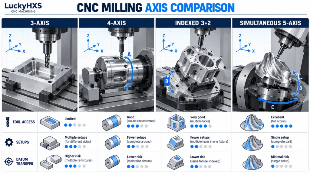
7. What Do 3-Axis, 3+2, 4-Axis, and 5-Axis Milling Mean?
Axis descriptions indicate the controlled directions or rotations available to position the tool and workpiece. A conventional 3-axis machining center moves along X, Y, and Z. It is well suited to plates, open pockets, top-side hole patterns, and features accessible from one direction.
A fourth axis adds controlled rotation, which can position or machine features around a part. In indexed 3+2 machining, two rotary axes orient the workpiece at a fixed angle and the machine then cuts with three linear axes. This can reduce manual re-clamping for multi-face housings. In simultaneous 5-axis machining, linear and rotary axes move together, helping the tool follow contoured surfaces or maintain a useful orientation on complex geometry.
More axes do not automatically make a part more accurate, economical, or suitable for production. A simple component may be more stable and efficient in a dedicated three-axis fixture. A five-axis part may still need multiple setups, special tools, or secondary finishing. Buyers should ask how the chosen route improves access, retains datums, reduces transfers, controls tool reach, and supports inspection of critical relationships. The 5-axis CNC machining page provides additional context for parts that genuinely need multi-axis access.
8. What Materials Can Be CNC Milled?
CNC milling can process many metals and engineering plastics, but “machinable” does not mean that every grade behaves the same. Material strength, hardness, ductility, thermal response, chip behavior, abrasiveness, and tendency to work-harden affect cutters, speeds, burrs, surface finish, and dimensional stability. Stock form and condition also matter.
LuckyHXS project records include review of aluminum grades such as 6061, 6063, 7075, 2024, and 5052; stainless steels including 303, 304, and 316-family grades; free-machining steels such as 1214 and 1215; brass and copper materials; and engineering plastics such as POM and PTFE. These examples are not a claim that every grade, temper, thickness, or certified stock form is always available. The exact material and supporting evidence must be confirmed for each RFQ.
Buyers should specify the alloy or resin, governing standard, temper or condition, required stock form, heat treatment, finishing compatibility, and any certificate or traceability need. If alternatives are allowed, define which mechanical, corrosion, thermal, electrical, cosmetic, or regulatory properties must remain equivalent and who can approve the substitution. Material-specific pages for aluminum CNC machining, stainless steel CNC machining, brass CNC machining, and plastic CNC parts provide more focused starting points.
9. What Kinds of Parts Are Best Suited to CNC Milling?
Good milling candidates usually contain accessible faces and features that can be reached by rotating cutters. Examples include equipment housings, mounting brackets, manifolds, fixture plates, covers, bases, valve blocks, electronics enclosures, instrument bodies, heat sinks, and low-volume tooling. Milling is also useful when several holes, bores, pockets, or mounting faces must maintain defined relationships to a common datum system.
The process can serve one-off engineering samples, functional prototypes, bridge production, and repeat batches. It is often chosen when the part needs the properties of solid engineering material, controlled interfaces, threaded assembly features, or better dimensional definition than an unfinished near-net process provides.
Milling may be less efficient when the part is almost entirely rotational, when a casting or extrusion already provides most of the economical shape, or when purchased standard hardware meets the function. High material-removal volume can also increase time and waste. Complex geometry does not automatically require milling if additive manufacturing, fabrication, turning, molding, or another route better suits the requirement. For early design choices, compare CNC machining and 3D printing using the actual material, quantity, geometry, finish, and acceptance needs.
10. What Are the Main Advantages of CNC Milling?
CNC milling can produce a wide range of precise, functional features from commercially available engineering materials. Once a validated process is established, programmed motion supports repeatability across parts and orders. Tool changes allow faces, pockets, holes, bores, threads, and chamfers to be combined in a coordinated route rather than treated as unrelated manual operations.
Other practical advantages include:
- Direct use of digital CAD and CAM data for controlled geometry
- Flexibility to revise programs and fixtures as a design matures
- Ability to machine several faces and feature types on one component
- Compatibility with prototypes, low-volume work, and repeat production
- Access to metals and plastics with useful structural, thermal, electrical, or wear properties
- Integration with probing, in-process checks, and dimensional inspection
- Clear connection between drawing datums and the machining setup
These advantages depend on good inputs and process control. CNC equipment does not guarantee that every dimension will be held, every surface will look identical, or every re-order will match an obsolete file. Repeatability requires controlled revisions, approved material, maintained tools and fixtures, defined finishing, and an agreed inspection plan.
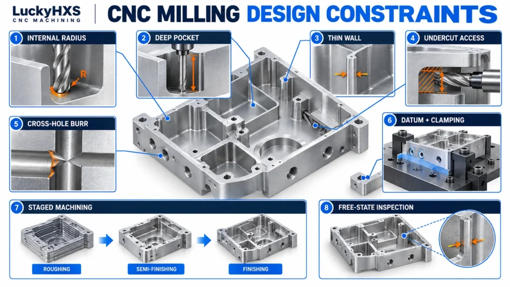
11. What Are the Main Limitations and Design Constraints?
CNC milling uses physical cutters, so tool shape and access impose real constraints. A round cutter leaves an internal radius; it cannot create a perfectly sharp internal corner. Deep pockets can require long, slender tools that are more prone to deflection and vibration. Narrow slots, small holes, undercuts, and enclosed features may require special tooling or may not be reachable from the proposed setup.
Workpiece behavior is equally important. Thin walls, broad plates, asymmetric material removal, high clamping force, and residual stress can cause temporary or permanent movement. A part may appear flat in a fixture and relax after release. Brass, stainless steel, aluminum, engineering plastics, and heat-treated materials respond differently to cutting heat, pressure, and finishing.
Design review should therefore address:
- Internal corner radii and tool access
- Pocket depth relative to opening width
- Unsupported wall height and local stiffness
- Clamping, datum surfaces, and allowable fixture contact
- Access to holes, threads, back-side features, and burr locations
- Material removal balance and staged roughing or finishing
- Features that change during heat treatment, anodizing, plating, or polishing
- Free-state versus restrained inspection conditions
The goal is not to remove every demanding feature. It is to identify which features are functional, which can be modified, and how the required result will be produced and verified.
12. What Tolerances and Surface Finishes Can CNC Milling Achieve?
There is no single tolerance or surface-finish value that applies to every CNC milled part. Capability depends on feature type and size, material, stock condition, tool access, cutter geometry, wall stiffness, setup count, temperature, finishing route, measurement method, and production quantity. A machine specification alone cannot establish the acceptable limits for a finished component.
The drawing should distinguish functional characteristics from general dimensions. Critical items may include bore size and fit, hole position, profile, flatness, parallelism, perpendicularity, sealing surfaces, mounting relationships, or the position of features across several faces. Each requirement needs a clear datum reference and must apply at the correct production stage.
Surface requirements also need precise language. “Smooth” and “good finish” are subjective. State a measurable surface-texture requirement where function demands it and identify cosmetic areas separately. If anodizing, plating, polishing, blasting, heat treatment, or another operation changes dimensions or appearance, define whether the drawing limits apply before or after finishing and which areas require masking. Tightening every dimension can increase setup, inspection, and scrap risk without improving function; the guide on how tight tolerances affect CNC machining cost explains that tradeoff.
13. How Are CNC Milled Parts Inspected?
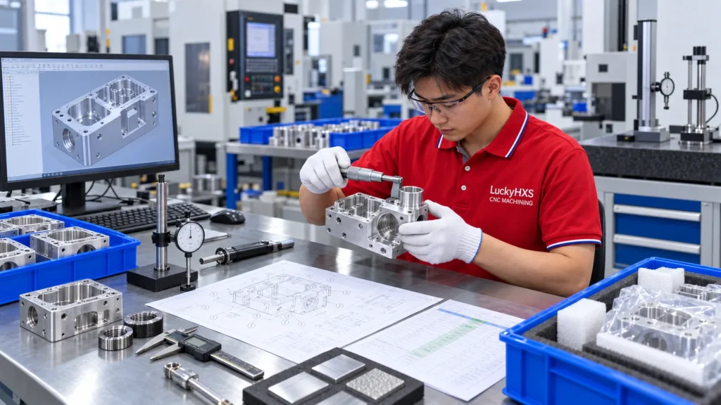
Inspection should follow the drawing’s functional requirements rather than a generic equipment list. The plan needs to identify what is checked, at which production stage, against which revision, by what method, at what frequency, and in what report format. Direct dimensions may be checked with micrometers, calipers, height gauges, pin gauges, bore gauges, or thread gauges. Geometric relationships, profiles, and multi-face positions may require indicators, optical systems, dedicated fixtures, or coordinate measurement.
The measurement setup must reproduce the drawing’s datum structure without distorting the component. This is particularly important for thin plates, flexible walls, plastics, sealing faces, and parts that move after unclamping. Surface treatment can also change bores, threads, fits, and appearance, so final-condition inspection may be necessary.
Before ordering, buyers should state whether they require first-part results, a first-article report, selected critical-characteristic data, a full dimensional report, material documentation, finish records, special-process evidence, or photographs. The required format, sample size, and acceptance rule should be agreed during quotation. The CNC machining quality inspection page provides a practical framework, while deburring services explains why edge and internal-intersection requirements also need explicit review.
14. Can CNC Milling Be Used for Prototypes and Repeat Production?
Yes. CNC milling can produce functional prototypes from the intended engineering material without requiring production tooling such as an injection mold. A prototype can test fit, assembly, sealing, fastening, thermal behavior, user interaction, or manufacturing access. It can also reveal drawing conflicts and inspection problems before a repeat order is released.
A prototype should not be treated as an informal object that replaces the drawing. Approval needs to reference the exact part number, revision, material, finish, inspection result, and any accepted deviation. If the design changes after testing, the buyer and supplier should determine whether a new sample, partial revalidation, or new first-article approval is needed.
For repeat production, a stable package preserves the approved process intent. It should identify the governing files, critical features, material evidence, finish, inspection records, packaging, and change-control method. Quantity can influence stock purchasing, fixture strategy, tool life planning, inspection sampling, and unit cost. The prototype CNC machining services page explains the validation stage; repeat production still requires order-specific confirmation rather than an assumed universal MOQ or lead time.
15. What Should Buyers Send for a CNC Milling Quote?
An accurate quotation needs enough information to define the finished deliverable and its acceptance basis. Send a controlled 2D drawing and matching STEP or STP model where available. The drawing should identify the part number and revision, material and condition, critical dimensions, datums, tolerances, threads, surface texture, edge requirements, final finish, and applicable notes.
Also include:
- Prototype quantity, immediate order quantity, and expected repeat demand
- Application and the features that control fit, sealing, alignment, or safety
- Material certificate, lot traceability, inspection report, or finish-document needs
- Cosmetic surfaces, protected edges, cleanliness, marking, and packaging requirements
- Destination, delivery basis, requested receipt date, and approval stages
- Which file governs if the model and drawing conflict
- Whether alternatives or design changes require written buyer approval
If only a sample exists, define how it will be measured, which wear or damage must not be copied, who approves the reconstructed drawing, and what controls final acceptance. Price and lead time then depend on material availability, stock size, removal volume, setups, fixtures, tooling, tolerances, finishing, inspection, documentation, quantity, packaging, and schedule dependencies. There is no responsible universal price, MOQ, or delivery promise for every custom milled part.
Request a CNC Milling Review
Send LuckyHXS your current 2D drawing and matching 3D model, or an approved sample with clear reconstruction instructions. Include the material, quantities, critical features, final finish, inspection records, packaging needs, destination, and requested receipt date.
The review should identify a project-specific machining route, open technical questions, quotation assumptions, included secondary operations, inspection basis, and schedule dependencies. Use the contact page to submit your CNC milling RFQ and files.